

POWER-MASTER 500 - Victor Technologies
POWER-MASTER 500 - Victor Technologies
POWER-MASTER 500 - Victor Technologies

Create successful ePaper yourself
Turn your PDF publications into a flip-book with our unique Google optimized e-Paper software.
430581-004 <strong>POWER</strong>-<strong>MASTER</strong> <strong>500</strong><br />
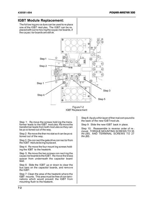
IGBT Module Replacement:<br />
The fol low ing pro ce dure can be used to re place<br />
one of the IGBT mod ules. The IGBT can be re -<br />
placed with out re mov ing the ca pac i tor boards, if<br />
the ca pac i tor boards are still ok.<br />
Step 1: Re move the screws hold ing the trans -<br />
former leads to the IGBT mod ules. Re move the<br />
trans former leads from both mod ules so they can<br />
be po si tioned out of the way.<br />
Step 2: Re move the ther mo stat so it can be po si<br />
-<br />
tioned out of the way.<br />
Step 3: Dis con nect the gate drive con nec tor from<br />
the IGBT mod ule be ing re placed.<br />
Step 4: Re move the four mount ing screws hold -<br />
ing the IGBT to the heatsink.<br />
Step 5: Re move the two screws con nect ing the<br />
ca pac i tor boards to the IGBT. Re move the brass<br />
spacer from un der neath the ca pac i tor board<br />
lead.<br />
Step 6: Slide the IGBT up or down to clear the<br />
bus bars on the ca pac i tor boards, and re move<br />
the IGBT.<br />
Step 7: Clean the area of the heatsink where the<br />
IGBT mounts. This area must be free of con tam i -<br />
na tions which would pre vent the IGBT from<br />
mounting flush to the heatsink.<br />
7-2<br />
Step 1<br />
Step 2<br />
Step 1<br />
Step 4<br />
Fig ure 7-2<br />
IGBT Re place ment<br />
Step 5<br />
Step 3<br />
Step 8: Ap ply a thin layer of ther mal com pound to<br />
the back of the new IGBT mod ule.<br />
Step 9: Slide the new IGBT back in place.<br />
Step 10: Re as sem ble in re verse or der of re -<br />
moval. TORQUE MOUNTING SCREWS TO 35<br />
IN-LBS, AND TER MI NAL SCREWS TO 27<br />
IN-LBS.


