Download 265R PDF - EXPRESSCUBE.com
Download 265R PDF - EXPRESSCUBE.com
Download 265R PDF - EXPRESSCUBE.com

Create successful ePaper yourself
Turn your PDF publications into a flip-book with our unique Google optimized e-Paper software.
Important<br />
ExpressCube Countertop <strong>265R</strong> User Guide - Copyright© by Global Sensor Systems Inc.<br />
All rights reserved<br />
ExpressCube is one of many state-of-the-art product lines designed and manufactured by Global Sensor<br />
Systems Inc.<br />
All information contained in this User Guide is subject to change without notice.<br />
ExpressCube products and technology are protected by domestic and international patents both issued<br />
and pending. U.S. Patent No. 7321859, 7373722 issued. Patents Issued Canada, Japan, and Mexico Patent<br />
Pending Europe, China, and India. For more details contact Canada 905-507-0007<br />
All ExpressCube , SizeIt software and firmware is protected by domestic and international copyrights.<br />
ExpressCube, Global ExpressCube , SizeIt, Resolution and the ExpressCube logo are registered<br />
Trademarks.<br />
Please address any <strong>com</strong>ments or suggestions regarding this user guide to:<br />
Global Sensor Systems<br />
400 Brunel Road,<br />
Mississauga, Ontario<br />
Canada L4Z 2C2<br />
Attention: Documentation<br />
For additional product information refer to our web site: www.expresscube.<strong>com</strong> or e-mail us:<br />
products@expresscube.<strong>com</strong><br />
For additional technical assistance please e-mail: support.expresscube@expresscube.<strong>com</strong><br />
2
Index<br />
1. General .................................................................................................................................. 5<br />
1.1. Introduction ........................................................................................................................ 5<br />
1.2. Specifications ..................................................................................................................... 5<br />
2. Equipment Setup ....................................................................................................................... 6<br />
2.1. Unpacking .......................................................................................................................... 6<br />
2.2. Location and Placement ..................................................................................................... 6<br />
2.3. Opening And Securing The Back Sensor Array ................................................................ 7<br />
2.4. Performing Lens Calibration .............................................................................................. 7<br />
3. Electrical Connections .............................................................................................................. 8<br />
3.1. Rear Connecting Panel Layout Summary .......................................................................... 8<br />
3.2. USB Connection ................................................................................................................ 9<br />
3.3. Connection of a Handheld Bar Code Scanner ................................................................... 9<br />
3.4. Printer Connection ........................................................................................................... 10<br />
3.5. ExpressCube External Device Ports ............................................................................. 10<br />
3.6. Power Adapter Connection .............................................................................................. 11<br />
4. User Control Selection for the ExpressCube TM System ............................ 12<br />
4.1. ExpressCube LCD Controller ...................................................................................... 12<br />
4.2. Computer Control ............................................................................................................ 12<br />
5. ExpressCube TM SizeIt TM Software Installation ............................................... 13<br />
5.1. Summary .......................................................................................................................... 13<br />
5.2. Minimum Computer Requirements ................................................................................. 13<br />
5.3. Software Installation ........................................................................................................ 13<br />
5.4. Running the Software ...................................................................................................... 13<br />
6. ExpressCube Countertop Power-up ................................................................. 14<br />
6.1. Power-up .......................................................................................................................... 14<br />
6.2. Initial Power-up System Check ....................................................................................... 14<br />
7. User Programming ........................................................................................................ 15<br />
7.1. Summary .......................................................................................................................... 15<br />
7.2. Using the ExpressCube Controller Keypad for Programming ..................................... 15<br />
7.3. Using the PC running ExpressCube SizeIt for Programming ................................... 15<br />
7.4. Main Programming Menu ................................................................................................ 16<br />
7.4.1. Alter Dimensional Weight [DIM] Factors ................................................................ 16<br />
7.4.2. Manual / Automatic Operation ................................................................................. 17<br />
7.4.3. Adjust Beep Duration ............................................................................................... 17<br />
7.4.4. Set Device Number ................................................................................................... 18<br />
7.4.5. Calibrate Lenses ....................................................................................................... 19<br />
8. Operation ........................................................................................................................... 20<br />
8.1. Summary .......................................................................................................................... 20<br />
8.2. Main unit LED indicators ................................................................................................ 20<br />
8.3. Preparation for Measurements ......................................................................................... 21<br />
8.4. Zeroing the ExpressCube Countertop .............................................................................. 21<br />
8.5. Placement of the Box for Measurement ........................................................................... 22<br />
8.6. Verifying That the Parcel is Ready to Measure ............................................................... 23<br />
8.7. Dimensional Weight and The Greater Weight Indicator ................................................. 24<br />
8.8. Acquiring the Measurement Data (Manual Operation) ................................................... 25<br />
8.9. SEND/PRINT the Acquired Measurement Data (Manual Operation) ............................. 26<br />
8.10. Automatic (ACQUIRE & SEND / PRINT) Operation ................................................. 26<br />
8.11. Using the ExpressCube Countertop as a Weigh Scale Only .................................... 28<br />
3
8.12. ExpressCube Print Out Format (RS-232C Port) ...................................................... 29<br />
8.12.1. Data Format........................................................................................................... 29<br />
8.12.2. Sample Outputs ..................................................................................................... 29<br />
9. Recording ExpressCube <strong>265R</strong> Data ..................................................................... 30<br />
9.1. General ............................................................................................................................. 30<br />
9.2. RS-232 Port...................................................................................................................... 30<br />
9.3. ExpressCube Data Logger Software ................................................................................ 30<br />
9.4. Automatic Data Capture Using Hand Scanner & Printer RS-232 Ports .......................... 31<br />
9.5. Third Party Software Development for ExpressCube <strong>265R</strong> USB Port ............................ 32<br />
10. Maintenance ................................................................................................................. 33<br />
10.1. General ......................................................................................................................... 33<br />
10.2. Cleaning (Excluding the Sensor Lenses) ...................................................................... 33<br />
10.3. Cleaning the Sensor Lens ............................................................................................. 33<br />
10.4. Replacing the Sensor Lens ........................................................................................... 34<br />
11. Troubleshooting .......................................................................................................... 34<br />
11.1. Summary ...................................................................................................................... 34<br />
11.2. ExpressCube Countertop will not power up ............................................................. 35<br />
11.3. ExpressCube Countertop Controller LCD display is not working ........................... 35<br />
11.4. ExpressCube Countertop PC Controller SizeIt is not working ................................ 36<br />
12. Appendix 1 : ExpressCube Warranty .............................................................................. 37<br />
12.1. Statement of Warranty. ................................................................................................ 37<br />
12.2. Terms and Conditions of Warranty. ............................................................................. 37<br />
12.3. Conditions Which Void Warranty. ............................................................................... 38<br />
13. Appendix 2: Dimensional Weight & DIM FACTOR .......................................................... 39<br />
13.1. The Importance of Volume and Weight of Cargo for Transportation .......................... 39<br />
13.2. Dimensional (Volume) Weight .................................................................................... 39<br />
13.3. DIM Factor (Dimensional Weight Factor) ................................................................... 40<br />
13.4. Using DIM Factor (Dimensional Weight Factor) ........................................................ 40<br />
13.5. Dim Factor Conversion Between in 3 /lb and cm 3 /kg ..................................................... 40<br />
14. Appendix 3: ExpressCube Tips and Techniques ................................................................ 42<br />
14.1. Dimensional Weight ..................................................................................................... 42<br />
14.2. How ExpressCube Measures Packages ........................................................................ 42<br />
14.3. How Laser & Light Curtain Conveyor Systems Measures Packages .......................... 43<br />
14.4. Know Your Courier’s Method of Calculating Dimensional Weight ............................ 43<br />
14.5. Minimizing Package Size ............................................................................................. 44<br />
14.6. Measuring Packages on ExpressCube Dimensioning Systems .................................... 45<br />
14.7. Measuring Irregular Cartons 1 With ExpressCube ........................................................ 46<br />
4
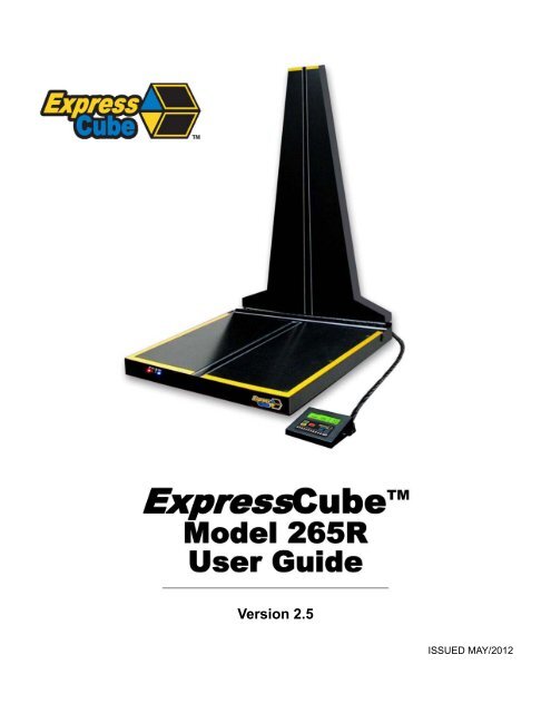
1. General<br />
1.1. Introduction<br />
The ExpressCube countertop unit will quickly and accurately dimension and weigh cuboidal<br />
packages. The ExpressCube countertop unit will calculate dimensional weight based on the<br />
acquired measurements and preprogrammed dim factors.<br />
Note: ExpressCube Resolution models 165R & <strong>265R</strong> incorporate fundamental changes in both<br />
hardware and software design. This manual does not apply to previous 150/250/165/265 models.<br />
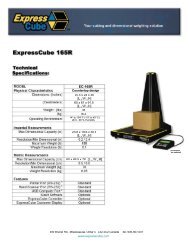
1.2. Specifications<br />
MODEL<br />
Physical Characteristics<br />
EC-<strong>265R</strong><br />
Dimensions: (Inches)<br />
25.7 x 23.5 x 43.2<br />
[L x W x H]<br />
(Centimeters)<br />
63.5 x 60 x 110<br />
[L x W x H]<br />
Weight : (lbs) 40<br />
(kg) 18<br />
Operating Environment<br />
14 o to 104 o F (-10 o to 40 o C)<br />
0 to 90 % N.C. Humidity<br />
Imperial Measurements<br />
Max Dimensional Capacity (in)<br />
23.8 x 25.8 x 37<br />
[L x W x H]<br />
Resolution/Min Dimensional (in) 0.2 / 2.4<br />
Maximum Weight (lb) 155<br />
Weight Resolution (lb)<br />
Metric Measurements<br />
0.1<br />
Max Dimensional Capacity (cm)<br />
60 x 65.5 x 94<br />
[L x W x H]<br />
Resolution/Min Dimensional (cm) 0.5 / 6.0<br />
Maximum Weight (kg) 70<br />
Weight Resolution (kg)<br />
Features<br />
0.05<br />
Printer Port (RS-232) 1<br />
Standard<br />
Hand Scanner Port (RS-232) 2<br />
Standard<br />
USB Computer Port 3 Standard<br />
SizeIt Software Optional<br />
ExpressCube Controller Optional<br />
ExpressCube Customer Display Optional<br />
Feature Notes: 1 Printer not included; 2 Hand Scanner not included; 3 Computer not included<br />
WMS/NTEP – WMS is a software configuration that removes many of the <strong>com</strong>mercial NTEP constraints dimensional<br />
measurements. All specifications are identical with the exceptions listed below:<br />
Specification NTEP WMS<br />
Minimum Dimensional Height 2.4 in / 6.0 cm 1.5 In / 4.0 cm<br />
Minimum Dimensional Length 2.4 in / 6.0 cm 2.4 in / 6.0 cm<br />
Minimum Dimensional Width 2.4 in / 6.0 cm 1.5 In / 4.0 cm<br />
Dimensional Increment 0.2 in / 0.5 cm 0.1 in / 0.1 cm<br />
Weight Increment 0.1 lb / 0.05 kg 0.01 lb / 0.01 kg<br />
5
2. Equipment Setup<br />
2.1. Unpacking<br />
The ExpressCube countertop unit is shipped with the back of<br />
the unit folded onto the platform. Carefully remove the unit<br />
from the packing material and place the unit in the final<br />
location.<br />
Unscrew the leveling feet until approximately one-half inch is<br />
extended from the bottom of the unit. This will allow maximum<br />
flexibility in leveling the unit.<br />
The ExpressCube countertop unit may be provided with<br />
optional display and connecting hardware. It is important to review the equipment list provided in the<br />
shipping container to ensure that all items have been removed prior to disposal of the shipping<br />
container.<br />
2.2. Location and Placement<br />
Refer to the specifications to obtain the outside dimensions of this model of ExpressCube countertop<br />
unit. This unit should be placed on a countertop or table that has a surface area that is equal or<br />
greater to the physical dimensions referred to in the specifications. It is important for accurate<br />
weight measurements that the surface is reasonably level, flat and stable.<br />
Ensure that the area selected for the ExpressCube countertop unit is free from objects that could<br />
touch the unit and that there is adequate space to place and measure packages without obstruction.<br />
The ExpressCube countertop unit should be located within four feet of a power source. Verify with<br />
the specifications and the power adapter shipped that the power source and the ExpressCube<br />
power adapter are <strong>com</strong>patible.<br />
IMPORTANT:<br />
• Do not place the ExpressCube <strong>265R</strong> on the floor. The unit is very susceptible to damage from<br />
collisions and dropped packages.<br />
• If the LCD Controller is used, place the cable and the unit away from the platform.<br />
• Check that the cables connected to the back panel are not collected or group such that they can<br />
inhibit the movement of the platform.<br />
• It is not necessary but it is re<strong>com</strong>mended that there is a surface area adjacent to the platform<br />
that measured parcels can be moved on or off.<br />
6<br />
ExpressCube Shipping / Storage
3. Electrical Connections<br />
3.1. Rear Connecting Panel Layout Summary<br />
Symbol Function Description<br />
* (unmarked) Calibration<br />
Power Switch Switches ExpressCube unit ON / OFF<br />
Power Adapter<br />
USB<br />
Hand Scanner<br />
Printer<br />
LAN Not Available<br />
External Devices<br />
*Authorized Personnel Only* Removal or damage to<br />
the calibration seal voids certification approvals<br />
The ExpressCube universal power adapter includes<br />
4 power connections and has the following world<br />
safety approvals: UL / ULC, CE, PSE, BS, GS, FCC,<br />
SAA<br />
This USB port can be used by a local PC to<br />
Operate and collect data from the ExpressCube unit.<br />
Connect to handheld scanner (not supplied).<br />
The port is a male RS-232 serial interface.<br />
RS-232 male port provides ASCII data output for either<br />
a printer or direct data logging onto a hard drive via a<br />
local PC application (not supplied).<br />
These connectors are used to connect ExpressCube<br />
external devices such as the customer display or<br />
control box.<br />
Connect all the appropriate connectors prior to connecting the power adapter and<br />
activating the device.<br />
The ExpressCube countertop unit is designed such that there is space to connect<br />
and run the cables from the rear connector panel. Do not use this space to bunch and store<br />
excess cable as the movement of the platform could be restricted by cable contact.<br />
8
3.2. USB Connection<br />
The ExpressCube countertop series of dimensioning<br />
devices are equipped with a USB connection to interface<br />
to a local <strong>com</strong>puter. The USB connection allows the<br />
<strong>com</strong>puter to control and capture data from the<br />
dimensioning device. The USB is fully <strong>com</strong>patible with<br />
USB 2.0 <strong>com</strong>puter ports. A USB driver is sent out as part<br />
of the User Guide CD contents. It is also installed with the<br />
SizeIt software.<br />
Connect the cable as indicated in the diagram.<br />
ExpressCube SizeIt must be installed in the<br />
<strong>com</strong>puter before the USB interface can be used. Refer to the ExpressCube SizeIt<br />
installation section for more details.<br />
3.3. Connection of a Handheld Bar Code Scanner<br />
The ExpressCube countertop unit has a dedicated<br />
male RS-232 serial port for use with a handheld bar<br />
code scanner. [Handheld scanner not supplied] The<br />
RS-232 connector should be securely connected to the<br />
appropriate connector on the ExpressCube<br />
countertop.<br />
There are two RS-232 connectors on the<br />
connector panel but each one serves different<br />
purposes. Be sure to use the connector identified<br />
for the hand scanner.<br />
The ExpressCube countertop unit has programming options that can utilize the<br />
trigger of the handheld scanner to activate data collection and processing. Refer to the<br />
Operators Program Menu for more details.<br />
Connection settings for hand scanners:<br />
1) Connection port – RS-232<br />
2) Baud rate - 9600<br />
3) Parity – none<br />
4) Data bits – 8<br />
5) Stop bit – 1 and add a suffix of a CR LF (Carriage Return Line Feed)<br />
9<br />
Sample RS-232 Hand Scanner
3.4. Printer Connection<br />
The ExpressCube countertop unit is equipped with a female<br />
RS-232 serial printer port. The port is activated when the<br />
ExpressCube countertop unit has acquired data through a<br />
successful measurement. Upon receiving a ‘Print’ <strong>com</strong>mand, the<br />
printer port will deliver the data in an ASCII format that is<br />
terminated with a line feed and carriage return. The RS-232<br />
connector should be securely connected to the appropriate<br />
connector on the ExpressCube countertop.<br />
The ExpressCube countertop unit has been specifically<br />
set up using the Star SP-300 Series ASCII model. While most<br />
ASCII RS-232 printers follow virtually identical data formats,<br />
the user is responsible to assure their selected printer is<br />
<strong>com</strong>patible to the Star-300 series format.<br />
For detailed description of the data format to the printer, refer to the Technical Data<br />
Summary in the appendix of this manual.<br />
3.5. ExpressCube External Device Ports<br />
The ExpressCube external ports are high-speed data and power ports that are used to connect to<br />
optional ExpressCube equipment. There are two external device ports on the rear connector<br />
panel. The two ExpressCube external devices supported by these ports are the control unit and<br />
the customer display unit as illustrated below.<br />
T<br />
The ExpressCube Controller has a reversible mounting plate that allows the controller to be<br />
converted from a desk mount (as shipped) to a wall mount. To change the configuration, remove<br />
the four screws holding the bracket. Rotate the mounting bracket 180° and secure with the same<br />
four screws.<br />
10<br />
Star SP-300
The ExpressCube external device ports use RJ-11 four wire connectors. Place or mount the<br />
device to be connected in the location that it will be used. Insert the RJ connector until an audible<br />
click is heard. Carefully route the cable and insert the RJ-11 connector into either one of the two<br />
ExpressCube external device ports.<br />
The RJ-11 is a popular jack used by manufacturers for a variety of different devices and<br />
purposes. DO NOT INSERT ANY OTHER MANUFACTURED DEVICE EQUIPPED WITH A RJ-11<br />
INTO THE <strong>EXPRESSCUBE</strong> DEVICE PORT. The attempted use of this RJ-11 port for any<br />
device other than an ExpressCube device can cause internal damage and void the<br />
warranty.<br />
The ExpressCube external device ports provide low voltage power to operate the<br />
circuits and backlit LCD displays of the external devices. Care should be taken to ensure that<br />
no foreign objects are inserted into these ports.<br />
3.6. Power Adapter Connection<br />
After connecting the appropriate connectors as detailed in<br />
Sections 3.1 to 3.7, insert the power adapter plug into the<br />
ExpressCube countertop rear connector panel.<br />
The cable from the rear of the unit to the adapter should be<br />
free from obstruction and located to prevent accidental<br />
removal from ExpressCube or the outlet. Securely connect<br />
the power plug into an electrical outlet.<br />
Use only ExpressCube power adapters with the ExpressCube countertop unit.<br />
The power adapter must have unrestricted airflow around it. Do not wrap or enclose the<br />
power adapter.<br />
11
4. User Control Selection for the ExpressCube TM<br />
System<br />
The ExpressCube Countertop system must have an operator controller to perform the<br />
measurement functions. The ExpressCube Countertop system can be controlled either by a<br />
desktop <strong>com</strong>puter using the USB interface or by using the ExpressCube LCD Controller. If a<br />
display is required to monitor the ExpressCube operation, it is re<strong>com</strong>mended to use the customer<br />
display.<br />
4.1. ExpressCube LCD Controller<br />
The use of the ExpressCube LCD Controller only requires the appropriate electrical connection as<br />
described in the section above. The installation of the SizeIt software is not required. Proceed to<br />
the power-up section of this user guide.<br />
4.2. Computer Control<br />
The use of a <strong>com</strong>puter to control the ExpressCube Countertop system will require the installation<br />
and use of the SizeIt software. Connect the USB cable as previously described and follow the<br />
instructions outlined in the ExpressCube SizeIt Software Installation section of this guide.<br />
In this User Guide, the term ‘control panel’ [underlined] will reference the device used to<br />
control the ExpressCube Countertop System. ( i.e. ExpressCube LCD Controller or local<br />
<strong>com</strong>puter running SizeIt software)<br />
When the ExpressCube LCD Controller is used to control the ExpressCube<br />
Countertop system, the USB port is still active and should not be connected to a PC. In the<br />
event that a USB port is connected to the <strong>com</strong>puter, the LCD Controller keypad will be<strong>com</strong>e<br />
inoperable. This is done to prevent two sources of control from operating the ExpressCube<br />
simultaneously.<br />
12
5. ExpressCube TM SizeIt TM Software Installation<br />
5.1. Summary<br />
The ExpressCube SizeIt software allows a local <strong>com</strong>puter to operate and gather data from the<br />
ExpressCube countertop unit with the USB port. This software must be installed and the USB<br />
connected prior to powering-up the ExpressCube countertop unit. The software is not required if<br />
the ExpressCube controller is used to control the countertop unit.<br />
5.2. Minimum Computer Requirements<br />
• Minimum 512 meg of available RAM<br />
• Pentium IV or better @ 2.0 GHz or better<br />
• Windows XP operating system<br />
• CD-ROM drive<br />
• Java version 1.5.0_06 or later<br />
5.3. Software Installation<br />
1. Close down all applications currently running on the PC.<br />
2. Insert the CD program disk into the CD-ROM drive of the <strong>com</strong>puter.<br />
3. Click the Windows ‘START’ button and select ‘RUN’<br />
4. Use the browse key to locate and select the ‘set-up’ file on the CD-ROM drive<br />
5. Run the selected file.<br />
Note - if you encounter recurring problems with the operation of the program, un-install<br />
Size-It and re-install.<br />
The person installing the software should have the appropriate system permissions to<br />
install the software, this will vary for the system & location, and this can be especially critical<br />
for Windows XP.<br />
5.4. Running the Software<br />
Use the Start / Program or Desktop menus to<br />
begin the SizeIt program. The program will<br />
open the control page as illustrated to the right.<br />
Select the highest “<strong>com</strong> number” on the drop<br />
menu to engage the USB (choice shown as<br />
‘<strong>com</strong> 7’ in example at right).<br />
The USB port will remain off when the<br />
ExpressCube countertop unit is not powered.<br />
The ‘Set-up’ key will not work until<br />
<strong>com</strong>munications is established on the USB link.<br />
13
6. ExpressCube Countertop Power-up<br />
6.1. Power-up<br />
Locate and activate the power switch located on the rear panel. Almost instantly, the power [RED]<br />
indicator LED will begin to flash and then remain lit. During the brief time that the LED is flashing,<br />
power has been applied to the main <strong>com</strong>puter and it has started its program initiation. The steady<br />
LED indicates that the power is on, the sensors are calibrated and the main <strong>com</strong>puter is operating<br />
properly.<br />
The four indicator LEDs on the front of the ExpressCube countertop unit are intended to<br />
give the user a quick summary of the current operation of the unit. These LEDs are controlled<br />
by the measuring device and are not affected by the controller ( including third party software<br />
). Always refer to the control panel display for detailed operational status.<br />
6.2. Initial Power-up System Check<br />
The motherboard enters a self-diagnostic routine in which errors are reported in a diagnostic log.<br />
The results of the diagnostic routine contain a summary of the polling the different subsystems of the<br />
ExpressCube<br />
This section just briefly describes the system checks carried out by the motherboard as it is powered<br />
up. It is carried out almost instantly and has no visible effect on the operation of the unit.<br />
1) SYSTEM CHECK – The system verifies the proper operation of on-board <strong>com</strong>ponents.<br />
2) CONFIGURATION – Each power up cycle, the motherboard polls and assigns addresses to the<br />
Integrated Transceiver Array that performs the package measurements.<br />
3) LOAD CELL – The motherboard verifies the operation of the load cells and programs the filters<br />
used in the digital interface.<br />
Any irregularities are recorded as maintenance codes and can only be accessed by a software<br />
header in the motherboard.<br />
The control panel will be ready for operation after the system check is performed<br />
[approximately 10 -15 seconds from power-up]. If the display or system does not appear to<br />
be functioning, please refer to the troubleshooting section. DO NOT ATTEMPT TO OPEN THE<br />
SYSTEM.<br />
14
7. User Programming<br />
7.1. Summary<br />
The ExpressCube countertop has a simple programming menu that allows the user to program the<br />
following characteristics:<br />
• Program dimensional weight factors.<br />
• Handheld bar code scanner Acquire & Print synchronization.<br />
• Adjust audible (beep) Note: Not Used in Resolution Models<br />
• Set device number.<br />
Generally the user programming is set once and rarely requires adjustment. All programmed<br />
selections are stored and will remain until changed through the user programming.<br />
User programmed features and data is stored on non-volatile memory and will be<br />
retained even if the ExpressCube countertop system is not powered.<br />
7.2. Using the ExpressCube Controller Keypad for Programming<br />
The ExpressCube Controller keypad has been<br />
designed to easily make adjustments using the<br />
user-programming feature. Respond on the<br />
numeric keys as directed by the display to make<br />
a menu selection.<br />
Use the UNITS key to toggle between in/lb and<br />
cm/kg. Use the ACQUIRE button to enter a<br />
typed numerical value.<br />
7.3. Using the PC running ExpressCube SizeIt for Programming<br />
The programming menu can be easily accessed from the PC running SizeIt software program by<br />
clicking the Settings [Prog] key using the mouse cursor. All menu selections can be selected by the<br />
mouse and normal PC keyboard functions can be used to edit data entries.<br />
15
7.4. Main Programming Menu<br />
7.4.1. Alter Dimensional Weight [DIM] Factors<br />
Selecting this menu allows the user to review or change any of the four dimensional factors<br />
used by the ExpressCube countertop <strong>com</strong>puter to calculate dimensional weight.<br />
Sub-menu:<br />
1. (Dim Factor) [Units]<br />
2. (Dim Factor) [Units]<br />
3. (Dim Factor) [Units]<br />
4. (Dim Factor) [Units]<br />
5. BACK<br />
Select the dim (dimensional weight) factor that you wish to change and verify the correct<br />
units before entering the new value.<br />
The dimensional weight factors can only have four digits with the last digit<br />
representing units or tenths. (e.g. 000.0 to 9999) Any entry of four or less digits will be<br />
assumed whole numbers unless a decimal is used. The maximum dim factor setting is<br />
276 in 3 /lb<br />
The Dim Factors are displayed in the units that they were originally input but the<br />
ExpressCube countertop <strong>com</strong>puter will convert the dimensional weight factors to<br />
match the units that are used.<br />
The dimensional factor displayed and output from the unit will always match the units<br />
that the measurements were taken.<br />
16
7.4.2. Manual / Automatic Operation<br />
This selection provides an option for an automatic recording of the measurement data after<br />
the data is collected. The automatic operation can significantly speed the measurement<br />
process and is used when there is no requirement to review acquired measurements before<br />
recording them.<br />
Manual Operation: If the ExpressCube is in a ready state to record the measurement, the<br />
user will press the Acquire key or (if equipped) the trigger of the handheld scanner. The<br />
acquired measurement data will be displayed but the user must activate the SEND / PRINT<br />
key to record the data. Removal of the package from the platform will clear any acquired<br />
measurements and prepare the device for a new measurement sequence.<br />
Automatic Operation: If the ExpressCube is in a ready state to record the measurement,<br />
the user will press the trigger of the handheld scanner (if equipped). The ExpressCube will<br />
record the measurements and automatically send the acquired data with the bar code as if<br />
the SEND button had been pushed. All acquired data will remain in the display until the<br />
parcel is removed from the ExpressCube platform.<br />
In Operating Software Versions 4.0.20 and later [manufactured after Jan/2011] the<br />
automatic operation will also permit the Acquire Button to Acquire & Send data in one<br />
operation.<br />
Sub-menu:<br />
MANUAL / AUTOMATIC OPERATION<br />
1. MANUAL <br />
2. AUTOMATIC<br />
3. GO BACK<br />
4. EXIT<br />
Press the appropriate number to select the desired operation mode. The current selection<br />
will be indicated by the beside it. After verifying the correct selection, use<br />
EXIT function to return to the main menu.<br />
7.4.3. Adjust Beep Duration<br />
This selection displayed but the beep tone is not used in the <strong>265R</strong> model.<br />
17
7.4.4. Set Device Number<br />
This selection allows the user to set a device number for the ExpressCube countertop unit.<br />
The device number is sent with each data message of acquired data. This device number<br />
can be used to track a box through a facility.<br />
Sub-menu<br />
CURRENT DEVICE NUM XXX (000-999)<br />
If device number requires change from the current number, type in the three-digit new device<br />
number. When the new device number is confirmed on the display, the program will<br />
automatically exit to the main menu.<br />
Pressing the PROG key will exit the menu without changing the device number.<br />
18
7.4.5. Calibrate Lenses<br />
1) Remove any boxes from the platform and gently wipe any accumulated dust from the<br />
surface of the lens with a cloth, towel, etc.<br />
2) From under the machine, turn the machine OFF by toggling the white power switch.<br />
3) Disconnect the USB connector (located beside the power cable).<br />
4) From under the machine, turn the machine ON by toggling the white power switch. The<br />
lights on the top of the machine will flicker with the red power indicator be<strong>com</strong>ing steady.<br />
5) ON the LCD Controller located by the machine, press the PROG button. A menu will<br />
appear.<br />
6) Press the number 5 key “Calibrate Dimensional Banks”<br />
7) Verify that the platform is empty, then press number 1 key “Calibrate Dimensional<br />
Banks”<br />
8) During the calibration process the Blue light will flash, then the Yellow, then the Green<br />
and finally the Blue light will flash. When the flashing has stopped, the lens has finished<br />
calibrating.<br />
9) Hit the PROG key to quickly return to normal operation.<br />
10) From under the machine, turn the machine OFF by toggling the white power switch.<br />
11) Reconnect the USB connector (located beside the power cable).<br />
12) From under the machine, turn the machine ON by toggling the white power switch. The<br />
lights on the top of the machine will flicker with the red power indicator be<strong>com</strong>ing steady.<br />
.<br />
Note: It is not necessary to power the ExpressCube Off & ON if the USB cable is<br />
not used.<br />
19
8. Operation<br />
8.1. Summary<br />
The ExpressCube countertop is a very accurate MDMD (Multi-Dimensional Measuring Device) that<br />
is capable of measuring cuboidal (rectangular/square) boxes with great precision. The<br />
ExpressCube countertop has built in controls to prevent erroneous readings. Even with these built<br />
in controls, the user must exercise care to follow these guidelines:<br />
• Boxes cannot exceed the dimension and weight listed in the specifications.<br />
• Boxes must be cuboidal ( i.e. rectangular or square).<br />
• Severely damaged packages or packages covered by excessive mud or ice can cause errors<br />
for both dimensions and weight.<br />
• Both the platform and the package being measured must be free from physical contact with<br />
surrounding objects.<br />
• Place objects on the platform – do not drop packages onto the platform.<br />
Keep the platform clean and free of dust build up to ensure optimum operating<br />
performance.<br />
8.2. Main unit LED indicators<br />
The main unit LED indicators are a set of four LEDs mounted on the<br />
front of the main platform of the ExpressCube countertop. They<br />
give an accurate status of the ExpressCube countertop main<br />
<strong>com</strong>puter and are unaffected by third party software.<br />
• Red – Power – A steady illumination indicates that the<br />
unit has power.<br />
• Yellow – Valid Dimension – A steady illumination<br />
indicates that the ExpressCube countertop has measured<br />
a parcel placed on the platform.<br />
• Green – Valid Weight – A steady illumination indicates<br />
that the ExpressCube countertop has weighed a parcel<br />
placed on the platform.<br />
• Blue – Zero - A steady illumination indicates that the<br />
ExpressCube countertop is in a zero (no-load) condition.<br />
The ExpressCube countertop programmed for NTEP will not attempt any new<br />
measurement until the unit has reached a zero condition after the removal of the previous<br />
package. The Yellow and Green LED indicators will remain in the ACQUIRED state until a<br />
zero condition is achieved after the last recorded measurement.<br />
20
8.3. Preparation for Measurements<br />
The ExpressCube countertop unit should be powered up and the ExpressCube control panel<br />
display finished the initial system check. Prior to starting measurements, it is re<strong>com</strong>mended that the<br />
platform and sensors be wiped with a damp rag to remove any accumulated dirt and/or debris. It is<br />
also re<strong>com</strong>mended that the lens is calibrated as described in Section 2.4<br />
Select the units and dimensional factor (if used) for measuring the parcel.<br />
8.4. Zeroing the ExpressCube Countertop<br />
The ExpressCube Countertop will not record any measurements unless the platform has recorded<br />
the Zero condition (weight of the platform in an idle condition) prior to a package being placed on the<br />
platform. After verifying that the measurement platform is empty, press the ‘ZERO’ function button<br />
on the ExpressCube control panel.<br />
The Blue LED under the platform will light and a zero condition will be indicated by the word ‘ZERO’<br />
on the display of the ExpressCube control panel. The Zero condition display for both of the<br />
ExpressCube control panels is illustrated below:<br />
ExpressCube Controller Display<br />
21
ExpressCube SizeIt Display<br />
8.5. Placement of the Box for Measurement<br />
Place the box to be measured flush against the<br />
back of the ExpressCube countertop such that<br />
one side of the box is in contact with the rear face.<br />
The orientation of the box is arbitrary as long as it:<br />
• Sits over the center array<br />
• Is flush (contact) to the back<br />
• Sits within the yellow guide lines<br />
The illustration shows an example of a box ready<br />
for measurement and indicates how the<br />
dimensions will be recorded.<br />
GS1 (a global standards organization) has<br />
released GDSN Package Measurement Rules<br />
that specify Height, Width and Length as<br />
assigned by the dimensions. Using this<br />
standard, the orientation of the box on the<br />
platform has no effect on the height, width and<br />
length dimensions that are recorded.<br />
ExpressCube Resolution systems has an option that will label dimensions according to the<br />
GSDN rules as defined in Section 5.2 Issue 1.11 [Oct 2010]. This option must be set by a<br />
qualified service technician. This option affects the data output and does not affect the<br />
standard displayed dimension labels.<br />
22<br />
Standard Dimensioning Orientation
8.6. Verifying That the Parcel is Ready to Measure<br />
Once the box is in place, the ExpressCube countertop unit will resolve the weight and dimensions.<br />
A successful measurement is indicated by the steady illumination of the yellow LED (valid<br />
dimension) and the green LED (valid weight) on the front of the platform. The ExpressCube control<br />
panel will also have valid measurement indicators with the actual measurements displayed.<br />
If the weight has not been resolved, the problem could be caused by:<br />
• The box weight exceeds specifications. Weight will read ‘OVER’<br />
• The ExpressCube countertop was not in a zero condition prior to the box placement on the<br />
platform.<br />
• The ExpressCube countertop is vibrating or moving that is preventing weight resolution.<br />
Commercial [NTEP] System: If any dimensions cannot be resolved, all dimensions will read ‘N / A’.<br />
Warehouse [WMS] System: Any resolved dimensions will be displayed. Only unresolved dimensions<br />
will display ‘N/A’.<br />
If a cuboidal package is placed within the yellow guidelines and there is not a valid dimension<br />
obtained, the problem could be caused by:<br />
• The box dimension does not fall between the minimum and maximum the specifications.<br />
• The box is not flush against all three dimensional arrays.<br />
• There is excessive dirt or an object blocking the measuring arrays.<br />
If the ExpressCube countertop is unable to resolve a valid dimension, it will behave as<br />
a weigh scale. In this condition, acquiring a measurement will only record the weight and a<br />
scan code (hand scanner optional).<br />
The ready to acquire condition (valid measurements) display for both of the ExpressCube control<br />
panels is illustrated below:<br />
ExpressCube Controller Display<br />
23
ExpressCube SizeIt Display<br />
8.7. Dimensional Weight and The Greater Weight Indicator<br />
The ExpressCube countertop can measure both dimensions and weight which it then calculates<br />
the Dimensional Weight based on the user selected Dim Factor. It is important to realize that<br />
Dimensional Weight is meaningless unless the Dim Factor used to obtain it is known. For this<br />
reason, Dimensional Weight that is acquired will be recorded with the Dim Factor used to calculate<br />
it. Similarly, the Dimensional Weight and Dim Factor will be sent with the data that ac<strong>com</strong>panies the<br />
measured data and scan code (optional). Since Dimensional Weight is a calculated weight;<br />
units are not displayed to prevent confusion with actual weight. Dimensional Weight is<br />
always the same units as actual weight.<br />
The greater weight indicator on the ExpressCube control panel is a visual aid to the user to quickly<br />
identify the greater of measured or calculated Dimensional Weight. The indicator is not sent with the<br />
acquired data.<br />
The greater weight indicator for each of the ExpressCube control panel is illustrated below:<br />
24
8.8. Acquiring the Measurement Data (Manual Operation)<br />
To record the measurement of the box on the ExpressCube countertop, activate the ACQUIRE<br />
button on the ExpressCube control panel. Alternatively (if equipped), the handheld scanner will<br />
activate the Acquire sequence while reading the bar code on the package. The acquired data will be<br />
displayed on the ExpressCube control panel display.<br />
If the data is not recorded, the user should refer to Section 8.7. and verify that the box is properly<br />
positioned for measurement.<br />
If the box is removed from the platform without the SEND/PRINT button activated, the<br />
acquired data will be lost and the ExpressCube countertop must return to the zero<br />
condition to start a new measurement.<br />
After a successful measurement is acquired, the valid measurement indicators both on<br />
the front panel of the main unit and the ExpressCube control panel are held until a new<br />
measurement procedure is started.<br />
Displayed below is the successful acquired measurement (ACQD) for both control panels.<br />
ExpressCube Controller Display<br />
ExpressCube SizeIt Display<br />
25
8.9. SEND/PRINT the Acquired Measurement Data (Manual Operation)<br />
The acquired measurement data can be sent to the printer and any other devices or ports connected<br />
to the ExpressCube countertop by activating the SEND/PRINT button on the ExpressCube<br />
control panel. The SEND / PRINT button will only respond once for every measurement taken.<br />
The ExpressCube countertop will attempt to successfully send the acquired measurement data<br />
through the various data ports until the ExpressCube countertop returns to a zero condition. Any<br />
measurement data that has not been sent or printed will be cleared from the transmission buffer<br />
when the ExpressCube countertop is in the zero condition.<br />
The ExpressCube Commercial [NTEP] System: control panel display will continue to<br />
hold the acquired data until the box is removed [i.e. Zero].<br />
The ExpressCube Warehouse [WMS] System: control panel display will continue to<br />
hold the acquired data until the weight on the platform changes.<br />
8.10. Automatic (ACQUIRE & SEND / PRINT) Operation<br />
This feature can be used when the AUTOMATIC OPERATION option is selected in the user<br />
program (Section 7.5.2). The ExpressCube countertop must be ready for acquiring a measurement<br />
(as described in Section 8.6.). To acquire and record the measurement of the box on the<br />
ExpressCube countertop, the handheld scanner will activate the Acquire and SEND / PRINT<br />
sequence while reading the bar code on the package. The ExpressCube countertop will receive the<br />
data from the handheld scanner and append it with the acquired measurement data. The acquired<br />
data will be displayed on the ExpressCube control panel display.<br />
The ExpressCube countertop will attempt to successfully send the acquired measurement data<br />
through the various data ports until the ExpressCube countertop returns to a zero condition. Any<br />
measurement data that has not been sent or printed will be cleared from the transmission buffer<br />
when the ExpressCube countertop returns to a zero condition.<br />
If the measurement data is not acquired, the user should refer to Section 8.6. and verify that the box<br />
is properly positioned for measurement.<br />
The ExpressCube control panel display will continue to hold the acquired data until<br />
the box is removed.<br />
After a successful measurement is acquired and sent, the valid measurement indicators<br />
both on the front panel of the main unit and the ExpressCube control panel are held until a<br />
new measurement procedure is started.<br />
26
The successful acquired and sent measurement display for both of the ExpressCube control<br />
panels is illustrated below:<br />
ExpressCube Controller Display<br />
ExpressCube SizeIt Display<br />
27
8.11. Using the ExpressCube Countertop as a Weigh Scale Only<br />
The ExpressCube countertop can be used to measure the weight of non-cuboidal objects or<br />
cuboidal objects that physically exceed the dimensioning specifications of the machine. This feature<br />
allows the user to determine weight on courier documentation packs, odd package shapes including<br />
shipping cylinders, etc.<br />
Place the package on the ExpressCube countertop platform to physically limit as much package<br />
over-hang as possible. The ExpressCube countertop will automatically reconfigure itself as a<br />
weigh scale when an object is detected on the platform that cannot be accurately dimensioned.<br />
The ExpressCube countertop unit acting as a weigh scale will indicate ‘N / A’ on all measurements<br />
and calculations based on dimensional measurements. (See illustrations below). Only the device<br />
number, weight and scan code (optional) are recorded during the Acquire sequence.<br />
To acquire and record a weight, use the same procedure and options as described in the previous<br />
sections for obtaining and recording dimensions.<br />
ExpressCube Controller Display<br />
ExpressCube SizeIt Display<br />
28
8.12. ExpressCube Print Out Format (RS-232C Port)<br />
8.12.1.Data Format<br />
Data from printer is set as follows:<br />
9600 b/sec<br />
8 bit<br />
No Parity<br />
1 Stop Bit<br />
No flow control is provided and there is no buffer. The print out can be easily monitored by using<br />
HyperTerminal on windows.<br />
8.12.2. Sample Outputs<br />
Weight and All Dimensions Resolved<br />
------------------------------------------------<br />
Device Number: 1<br />
Height 10.0 in<br />
Width: 9.9 in<br />
Length: 12.4 in<br />
Gross Weight: 4.03 lb<br />
Dimensional Weight: 6.33<br />
Dimensional Factor: 194.0<br />
Barcode: 051047K004<br />
------------------------------------------------<br />
Weight and Any Dimension Unresolved ExpressCube Commercial [NTEP] System<br />
------------------------------------------------<br />
Device Number: 1<br />
Gross Weight: 4.03 lb<br />
Barcode: 051047K004<br />
------------------------------------------------<br />
29
Weight and Width Dimension Unresolved ExpressCube Warehouse [WMS] System *<br />
------------------------------------------------<br />
Device Number: 1<br />
Height 4.1 in<br />
Length: 12.1 in<br />
Gross Weight: 4.03 lb<br />
Barcode: 051047K004<br />
------------------------------------------------<br />
* ExpressCube Warehouse [WMS] System will print any resolved dimension.<br />
If a hand scanner is not used with The ExpressCube <strong>265R</strong>, the print out is identical to<br />
those indicated above except the 'Barcode:' line is not printed.<br />
9. Recording ExpressCube <strong>265R</strong> Data<br />
9.1. General<br />
There are two locations that data is available from the ExpressCube <strong>265R</strong>. The printer RS-232 port provides<br />
an ASCII text data output when the ExpressCube <strong>265R</strong> performs a measurement. The data can be read<br />
through the USB interface by use of a defined protocol of <strong>com</strong>munication to retrieve the data.<br />
9.2. RS-232 Port<br />
The data can be captured from the ExpressCube <strong>265R</strong> RS-232 Printer port by using a null modem cable to<br />
modify the data protocol between two DTE [Master} devices. Note that control leads are not used. The<br />
ExpressCube Null Modem Cable Part # ECP-NUL-A is re<strong>com</strong>mended.<br />
9.3. ExpressCube Data Logger Software<br />
ExpressCube Data Logger is a free Windows software written in visual basic that collects data from the<br />
ExpressCube <strong>265R</strong> and stores it on the host <strong>com</strong>puter in a text file that can be imported into a variety of<br />
software programs. The user can set up the text file to be recorded including the file name, data fields and the<br />
delimiters used. A null modem cable (e.g. ExpressCube part ECP-NUL-A) is used to connect the RS-232<br />
ports of the ExpressCube and host <strong>com</strong>puter.<br />
A copy of ExpressCube TM Data Logger with a user guide is included with each User<br />
Guide CD shipped with the ExpressCube TM system.<br />
30
9.4. Automatic Data Capture Using Hand Scanner & Printer RS-232 Ports<br />
A simple method of initiating an ExpressCube <strong>265R</strong> measurement can achieved by using the hand scanner port<br />
to initiate a measurement (ExpressCube <strong>265R</strong> must be in Automatic mode - see Section 7.4.2). This method<br />
is very popular among users that do not want to develop the more <strong>com</strong>plex USB interface to control the<br />
machine and capture data.<br />
A third party software (ExpressCube does not provide this application) is developed/ modified to control a RS-<br />
232 port that is connected to the ExpressCube <strong>265R</strong>. Any data transmitted on the RS-232 port is delivered to<br />
the hand scanner port of the ExpressCube <strong>265R</strong>. The data measurements from the ExpressCube <strong>265R</strong> is<br />
received on the data receive of the same RS-232 <strong>com</strong>puter port.<br />
The user inputs the related information required by the third part software (e.g. destination, type,<br />
transportation, etc) and when <strong>com</strong>pleted either hits a key or uses a hand scanner connected to the third party<br />
software to start a measurement. The third party software sends a CR/LF (Carriage Return/ Line Feed) to the<br />
Rs-232 port to initiate the measurement cycle from the ExpressCube <strong>265R</strong>. The data is received from the<br />
same RS-232 port.<br />
ExpressCube sells a modem cable specifically designed for this application: Dual End Null Modem Cable part<br />
# ECP-DUL-A<br />
A sample of this application is included in the illustration below:<br />
31
9.5. Third Party Software Development for ExpressCube <strong>265R</strong> USB Port<br />
There is third party proprietary software available that uses the ExpressCube USB port to both control and<br />
collect data from the ExpressCube <strong>265R</strong>. These are the same protocols that is used by the ExpressCube SizeIt<br />
software to control and display data.<br />
ExpressCube provides the protocol and related engineering libraries to software developers free of charge.<br />
ExpressCube does not provide any other support, testing or certification for third party applications.<br />
For more details and access to ExpressCube USB protocol information, please send an e-mail that includes<br />
your name and <strong>com</strong>pany details to: xsoftware.interface@expresscube.<strong>com</strong><br />
When diagnosing a problem with ExpressCube operation with a third party software,<br />
always remove the software and verify normal manual operation to prevent unnecessary<br />
service charges.<br />
ExpressCube does not provide support for any third party applications that are used<br />
with the ExpressCube <strong>265R</strong>. All support questions should be directed to the software<br />
vendor.<br />
32
10. Maintenance<br />
10.1. General<br />
The ExpressCube countertop unit is a sealed certified device that does not require any internal<br />
periodic maintenance. In the event that the unit has incurred physical damage that may affect the<br />
operation of the unit, it should be sent back to an authorized service center for repair and recalibration.<br />
10.2. Cleaning (Excluding the Sensor Lenses)<br />
To maintain the optimum performance of the ExpressCube countertop, the unit should be<br />
periodically cleaned to remove any build-up of dust and dirt. The black metal areas should be<br />
cleaned separately from the sensing strips. Use a damp cloth with a mild detergent and rinse with a<br />
clean damp cloth. Hand pumped sprayers can be used. Apply a non-corrosive cleaner to stubborn<br />
areas but care should be exercised to keep spray from the sensor strips.<br />
Do not use any volatile liquids to clean the surface. This is an electronic device and<br />
trapped fumes in the enclosure could be ignited by the electronic circuitry.<br />
Do not use any pressurized liquid source (e.g. water hose, steam jet, etc) to clean the<br />
unit.<br />
10.3. Cleaning the Sensor Lens<br />
It is important to keep the sensor lenses clean and free from any debris that may obscure the<br />
package from sensors. Use a soft clean cloth with <strong>com</strong>mercial glass cleaner to clean the surface of<br />
the lens.<br />
Do not use abrasive or dry cleaners on the lens.<br />
33
10.4. Replacing the Sensor Lens<br />
If a sensor lens be<strong>com</strong>es foggy (opaque) from wear, cracked or broken it should be replaced. All<br />
three lenses have a cover to permit safe and quick replacement of the lens. The covers are held on<br />
by two screws and there locations are illustrated below.<br />
11. Troubleshooting<br />
11.1. Summary<br />
The ExpressCube countertop is a multi-dimensional precision instrument designed to work in a<br />
variety of working environments. The internal assembly is sealed to preserve the integrity of this<br />
measuring instrument. There are a number of problems that may arise that can be addressed<br />
without tampering with the seals which are reviewed in this section along with problems involving<br />
possible parts replacement.<br />
This section addresses problems that are occurring in lieu of the device being properly<br />
installed, cleaned and operated as per the above sections.<br />
Only authorized technicians may break the seals to perform repairs on the ExpressCube<br />
countertop unit. Unauthorized personnel breaking the seals for any reason will void the<br />
government certification and possibly void the warranty on the unit.<br />
34
11.2. ExpressCube Countertop will not power up<br />
Symptom: The unit is connected to the power supply that is connected to power but the operation of<br />
the OFF-ON switch has no affect. The red LED on the front of the platform is off.<br />
Check (in numerical sequence):<br />
1. Physically verify the connections of the power adapter to the power outlet and the<br />
ExpressCube countertop power connector.<br />
2. Verify the power outlet by connecting a lamp or other known operational device.<br />
3. (Technician only) Remove the power adapter from the ExpressCube countertop unit<br />
and verify that the voltage to the ExpressCube countertop is present [15 VDC]. If<br />
the voltage is not present, contact your sales representative for a new power adapter.<br />
4. Contact your service center to arrange repair by a qualified service representative.<br />
11.3. ExpressCube Countertop Controller LCD display is not working<br />
Symptom: The LCD display on the Controller either does not display any intelligent characters or<br />
cannot control the ExpressCube Countertop.<br />
Check (in numerical sequence):<br />
1. Check that the red LED on the front panel of the ExpressCube Countertop is steady. If not<br />
steady, turn off the unit and remove power cord for 30 seconds. Reconnect the power and<br />
turn the power ON. If LED continues to flash, contact your service center to arrange repair<br />
by a qualified service representative.<br />
2. Physically check the cable (authentic ExpressCube part) and the connections to both the<br />
ExpressCube Countertop connector panel and the Controller.<br />
3. Switch the connecting cable to the alternative external connector on the ExpressCube<br />
Countertop connector panel.<br />
4. (Technician only) Use an Ohm meter to verify the cable conductivity and visually inspect the<br />
RJ connectors for physical damage.<br />
5. Contact your service center to arrange repair by a qualified service representative.<br />
35
11.4. ExpressCube Countertop PC Controller SizeIt is not working<br />
Symptom: The SizeIt software program running on the PC is not <strong>com</strong>municating with the<br />
ExpressCube Countertop.<br />
Check (in numerical sequence):<br />
1. Check that the red LED on the front panel of the<br />
ExpressCube Countertop is steady. If not<br />
steady, turn off the unit and remove power cord for<br />
30 seconds. Reconnect the power and turn the<br />
power ON. If LED continues to flash, contact your<br />
service center to arrange repair by a qualified<br />
service representative.<br />
2. Turn off the program in the <strong>com</strong>puter and remove<br />
the USB cable until a tone is heard from the<br />
<strong>com</strong>puter. Put in the USB and wait for a <strong>com</strong>puter<br />
tone again. Restart the SizeIt software.<br />
3. If the SizeIt program is still indicating that there is not USB connection; physically check the USB<br />
cable connections to both the ExpressCube Countertop connector panel and the Controller.<br />
4. If the SizeIt program is still indicating that there is not a USB connection, replace the USB cable.<br />
5. (IT Technician only) Verify proper hardware and software operation of personal <strong>com</strong>puter (PC).<br />
ExpressCube warranty only relates to the ExpressCube provided products as outlined in the<br />
Warranty in Appendix 1.<br />
6. Contact your service center to arrange repair by a qualified service representative.<br />
36<br />
USB<br />
OFF<br />
SizeIt Display for<br />
No USB Communication
12. Appendix 1 : ExpressCube Warranty<br />
12.1. Statement of Warranty.<br />
GLOBAL SENSOR SYSTEMS INC.<br />
NEW PRODUCT LIMITED WARRANTY<br />
Subject and according to the Terms and Conditions set forth below, Global Sensor Systems Inc. warrants to<br />
the Buyer that the new ExpressCube Countertop multi-dimensioning device (the “Product”) is in accordance<br />
with the manufacturer’s published specifications at the time of sale and that such Product shall be free from<br />
manufacturing defects in material and workmanship for a period of one year from, as applicable: the date of<br />
sale or the Commencement Date of use when installed by an authorized service representative (the<br />
“Warranty Period”). For purposes of this warranty, the term “Buyer” shall mean and refer only to the party<br />
which originally – whether from Global Sensor Systems Inc. directly, or from a distributor, agent or reseller<br />
authorized by Global Sensor Systems Inc. – purchases the Product as the end user which is the subject of<br />
this warranty.<br />
12.2. Terms and Conditions of Warranty.<br />
This warranty is applicable exclusively to the original Product and <strong>com</strong>ponents (if any) delivered with the<br />
Product as part thereof which were acquired from the manufacturer and resold by Global Sensor Systems<br />
Inc. Except as specifically warranted herein, Global Sensor Systems Inc. does not warrant, for any purpose,<br />
any part or <strong>com</strong>ponent manufactured by another manufacturer. This warranty does not apply to any part or<br />
<strong>com</strong>ponent which is used or rebuilt. Global Sensor Systems Inc. obligation and liability under this warranty<br />
is expressly limited to repair or replacement (at its option) of the warranted equipment or <strong>com</strong>ponents within<br />
the Warranty Period. A purchase by Buyer of equipment first leased or rented from an authorized Global<br />
Sensor Systems Inc. agent shall not start a new Warranty Period.<br />
In the event of the occurrence of a claim under this warranty, the Buyer shall have a duty to promptly notify<br />
Global Sensor Systems Inc. in writing of the nature and specifics of the claimed defect. Failure to so notify<br />
shall void this warranty. Any claim of a warranted defect is subject to inspection and analysis by Global<br />
Sensor Systems Inc. to conclusively identify or confirm the nature and cause of failure and application of<br />
this warranty. Any defective <strong>com</strong>ponents, mechanical or electrical, will be repaired or replaced, at the<br />
discretion and authorization of Global Sensor Systems Inc., at Global Sensor Systems Inc.’s facilities in<br />
Mississauga, Ontario, Canada or at an authorized agent facility. It shall be the Buyer’s responsibility to<br />
return the faulty equipment or <strong>com</strong>ponents to Global Sensor Systems Inc. at Buyer’s expense. Global<br />
Sensor Systems Inc. obligation shall not include transportation charges, nor labour, material, or service<br />
charges involved in the removal, return or installation of equipment or <strong>com</strong>ponents.<br />
37
Except as provided herein, Global Sensor Systems Inc. shall have no other obligation or liability due to<br />
defective equipment or <strong>com</strong>ponents. Accordingly, but without limitation, Global Sensor Systems Inc. shall<br />
not be liable for: losses, injury or damage caused to persons or property by Global Sensor Systems Inc.<br />
products or their failure; indirect, special or consequential damages of any nature including but not limited to<br />
loss of profit, delays or expenses, such as those arising from the use of or inability to use the products; nor<br />
any incidence of personal injury or property damage arising from the negligence or willful act of anyone.<br />
Global Sensor Systems Inc., for itself and the manufacturer, reserves the right to incorporate improvements<br />
in material and design applicable to the type or model of products to which the covered Product relates<br />
without notice and without any obligation or duty, whatsoever, to incorporate the same improvements in<br />
equipment previously manufactured.<br />
12.3. Conditions Which Void Warranty.<br />
This agreement shall not apply to equipment or <strong>com</strong>ponents which has/have:<br />
A. Been the subject of repairs or modifications not authorized by Global Sensor Systems Inc.<br />
B. Not been operated under normal use and service according to that for which it was intended.<br />
C. Not been operated or maintained in accordance with printed instructions.<br />
D. Been subject to misuse, damaged, negligent handling, improper installation, accident, damage by<br />
fire, submersion, or act of God.<br />
E. Had serial numbers altered, defaced or removed.<br />
F. Been sold, loaned, leased, subleased or in any other way transferred to or placed within the control<br />
of any party other than the Buyer.<br />
G. Been operated beyond capacity.<br />
THE FOREGOING IS IN LIEU OF ALL OTHER REMEDIES, GUARANTEES, LIABILITIES OR<br />
WARRANTIES. GLOBAL SENSOR SYSTEMS INC. MAKES NO OTHER WARRANTY, EXPRESS OR<br />
IMPLIED, AND MAKES NO WARRANTY OF MERCHANTABILITY OR FITNESS FOR ANY PARTICULAR<br />
PURPOSE.<br />
This statement sets forth the full extent of Global Sensor Systems Inc. liability for breach of any warranty or<br />
deficiency in connection with the sale or use of the Product. No employee or representative of Global<br />
Sensor Systems Inc. is authorized to change this warranty in any way or grant any other warranty.<br />
38
13. Appendix 2: Dimensional Weight & DIM FACTOR<br />
13.1. The Importance of Volume and Weight of Cargo for Transportation<br />
All cargo space involved in transporting goods has physical limits based on the volume of the cargo<br />
and the weight. Once a cargo has reached a limit in either volume or weight – the container (trailer,<br />
train, plane or shipping container) is transported. Weight has traditionally been the measurement<br />
which the transportation costs of individual packaged freight has been calculated.<br />
The difference in weight and volume costs can be appreciated if one considered the expense of<br />
transporting a large volume with little weight (e.g. large boxes of Styrofoam drinking cups).<br />
Transportation <strong>com</strong>panies have recognized these variables and most have allocated a volume per<br />
weight standard in their billing to capture cargo of light density.<br />
13.2. Dimensional (Volume) Weight<br />
The dimensional weight (also known as volume weight) is the minimum weight that a package a<br />
given size may have that is handled by a carrier. A carrier may state that any package of one cubic<br />
foot (12”x12”x12”) will have a minimum weight allowance of 10 pounds. If the cubic foot package<br />
actually weighs 8 pounds – it will be invoiced for 10 pounds. This is a minimum weight allowance –<br />
if the cubic foot package weighs 12 pounds – the charges will be based on 12 pounds.<br />
There are no international or domestic standards concerning values of dimensional<br />
weight. A significant number of courier <strong>com</strong>panies use the dimensional weight standard set<br />
by the International Air Transport Association (IATA) but many define their own dimensional<br />
weights.<br />
The value of dimensional weights will probably change as the nature of shipments change over time.<br />
Organizations such as the International Air Transport Association (IATA) have produced studies that<br />
suggest the density of packaging is changing as the <strong>com</strong>modities be<strong>com</strong>e more high tech. As a<br />
result the IATA itself has already passed a resolution (Resolution 501) to change the IATA<br />
dimensional weight.<br />
39
13.3. DIM Factor (Dimensional Weight Factor)<br />
The DIM factor is a mathematical factor used to calculate the dimensional weight of an object. The<br />
DIM factor represents the volume of a package allowed per unit of weight. Although mathematically<br />
related, the DIM factor is different for measurements in units of inches/pounds and for<br />
measurements in centimeters/ kilograms.<br />
All major courier <strong>com</strong>panies now apply the DIM Factor to every cuboidal (rectangular/ square) parcel<br />
that they handle to determine the dimensional weight. They then adjust customer invoicing to reflect<br />
charges based on the greater weight between actual weight and dimensional weight.<br />
Finding a DIM Factor using in/lb<br />
Find the DIM factor if each cubic foot (12”x12”x12”) has a minimum weight allowance of 10 pounds:<br />
1 cu ft 12”x12”x12” 1728 in 3<br />
10 lbs 10 lbs 10 lbs<br />
Finding a DIM Factor using cm/kg<br />
40<br />
172.8 in 3 /lb<br />
Find DIM factor if each cubic meter (100cm x 100cm x 100cm) has a minimum weight allowance of<br />
200 kg:<br />
1 m 3<br />
100cm x100cm x100cm 1000000 cm 3<br />
200 kg 200 kg 200 kg<br />
13.4. Using DIM Factor (Dimensional Weight Factor)<br />
5000 cm 3 /kg<br />
The DIM Factor provides a quick determination of the dimensional weight of any cuboidal package.<br />
The best way to describe this application is by an example of the application and use of the DIM<br />
Factor by a courier <strong>com</strong>pany:<br />
What is the billing rate of a 10”x 12”x 14” package that weighs 8 lbs by a courier that has a minimum<br />
dimensional weight of 10 lbs per cubic foot (i.e.: DIM Factor = 172.8 in 3 /lb) ?<br />
Volume Volume 10x12x14 in 3<br />
1680 in 3 lb 9.7 lb<br />
DIM Factor Volume / lb 172.8 in 3 /lb 172.8 in 3<br />
The courier <strong>com</strong>pany will invoice based on 9.7 lbs – the dimensional weight.<br />
This is an example. Some courier <strong>com</strong>panies always round dimensional weight up to<br />
the next pound, which in this sample would make the billing weight 10lbs.<br />
13.5. Dim Factor Conversion Between in 3 /lb and cm 3 /kg
The ExpressCube Countertop will automatically adjust the selected DIM Factor to correspond to the<br />
units selected by the user. The mathematical relationship between DIM Factors can be expressed<br />
as follows:<br />
Dim Factor [cm 3 /kg] = Dim Factor [in 3 /lb] x 36.12728079<br />
Dim Factor [in 3 /lb] = Dim Factor [cm 3 /kg] x 0.027679913<br />
Some DIM Factors maybe provided in both units such as the IATA value of Dim Factor<br />
166 in 3 /lb or Dim Factor 6000 cm 3 /kg. These have been slightly modified for ease of<br />
application. The ExpressCube countertop will correctly convert a user-selected input of Dim<br />
Factor 166 in 3 /lb to Dim Factor 5997 cm 3 /kg. This 0.05% difference is not large enough to<br />
affect dimensional weight readings. The user can input another DIM Factor of 6000 cm 3 /kg if<br />
desired and choose from two different Dim Factor selections depending on the units<br />
selected.<br />
41
14. Appendix 3: ExpressCube Tips and Techniques<br />
14.1. Dimensional Weight<br />
Virtually every courier <strong>com</strong>pany is now calculating an allowable (dimensional) weight for the size of<br />
the package that you are shipping. If your dimensional weight exceeds the actual weight, you will be<br />
charged based on the dimensional weight 1 .<br />
It is important that you understand how dimensioning equipment works, how your courier <strong>com</strong>pany<br />
determines the dimensional weight and the impact of proper packaging to minimize shipping costs.<br />
1 For a detailed description of the mathematics of dimensional weight and DIM factors, read<br />
Understanding Dimensional Weight and DIM FACTORS included in your ExpressCube Operators<br />
Guide or obtain a free copy from the ExpressCube website ( www.expresscube.<strong>com</strong> )<br />
14.2. How ExpressCube Measures Packages<br />
The ExpressCube product line obtains dimensions by<br />
measuring the dimensions of three faces of the<br />
package placed on the machine. Each measurement<br />
is taken 90˚ from the axis of the other two<br />
measurements.<br />
One measurement axis (length) is fixed on an edge but<br />
the other two axis do allow the operator to determine<br />
the point of measurement (illustrated in red). This is<br />
useful when measuring irregular packages as<br />
explained later in this document.<br />
42
14.3. How Laser & Light Curtain Conveyor Systems Measures Packages<br />
Many large courier <strong>com</strong>panies use automated (in-line) conveyor dimensioning systems to arrive at a<br />
dimensional weight. These systems may use a speed-based tachometer to measure the length of<br />
the parcel traveling on the conveyor and either a laser scanner or a light curtain (emitters/receivers)<br />
to determine height and width.<br />
These automatic dimensioning<br />
systems are able to provide<br />
dimensions quickly. Without human<br />
intervention, automated devices<br />
measure the largest dimension on<br />
each axis irrespective if it is an actual<br />
part of the box, a fat packet of<br />
documents or a bulging flap. On a<br />
recent visit to a large courier depot,<br />
this author was able to change the<br />
chargeable weight indicated on a<br />
Laser dimensioning system by placing<br />
a pencil on top of the parcel.<br />
Appreciating the nature of the automatic systems allows shippers to package wisely and predicts the<br />
effect of the deformed boxes using the ExpressCube countertop unit (detailed below).<br />
14.4. Know Your Courier’s Method of Calculating Dimensional Weight<br />
It is possible for two different courier <strong>com</strong>panies to use the same DIM factor on the same package<br />
and arrive at two different dimensional weights for calculating courier charges.<br />
The mathematical formula for determining dimensional weight for a package using a set DIM Factor<br />
is equal to volume (LxWxH) divided by the DIM Factor. The ExpressCube dimensional weight<br />
calculation utilizes straight mathematics obtained by multiplying the displayed dimensions and<br />
dividing by the DIM Factor.<br />
The mathematical dimensional weight of a package 12¼ “ x 18½ “ x 24¼ “<br />
DIM Factor = 194:<br />
Volume Volume 12.25x18.5x24.25 in 3<br />
5496 in 3 lb 28.3 lb<br />
DIM Factor Volume /<br />
lb<br />
194 in 3 /lb 194 in 3<br />
43<br />
Automatic (In-line) Dimension Systems
There are some courier <strong>com</strong>panies that round up measurements before they are used in<br />
calculations. This can have a significant cost impact, particularly on smaller packages. These<br />
courier <strong>com</strong>panies would calculate the dimensional weight as follows:<br />
The rounding up method to calculate dimensional weight of a package<br />
13 (12¼) “ x 19 (18½) “ x 25 (24¼) “ DIM Factor = 194:<br />
Volume Volume 13x19x25 in 3<br />
6175 in 3 lb 31.8 lb<br />
DIM Factor Volume / lb<br />
194 in 3 /lb 194 in 3<br />
In this example, subtle differences currently in use by two major couriers to calculate the<br />
dimensional weight of the same package would result in one charge based on 28.3 lb and another<br />
charge based on 31.8 lb.<br />
14.5. Minimizing Package Size<br />
Long gone are the days when a small item is thrown in an oversized carton and then surrounded in<br />
foam chips. It is possible to quickly surpass the value of the protected item with excessive shipping<br />
cost if a careful analysis is not used to determine the appropriate insulation required to protect an<br />
item.<br />
While it is important to keep the size of the carton to a minimum, it is also important to find boxes<br />
that fit the item to be shipped properly. If an irregular item is presented to most courier <strong>com</strong>panies,<br />
they will calculate the dimensional weight based on ‘the minimum dimensions of a carton that would<br />
contain the irregular package’. Loosely translated, the maximum measurements obtained by the<br />
automatic dimensioning systems will be used to determine the dimensional weight for invoicing.<br />
Courtesy Cardinal Couriers<br />
These actual photos illustrate how sloppy packaging can incur<br />
extra shipping costs from dimensional weight. If the item<br />
pictured in the left photo was placed flat in a fitted box there<br />
could have been a 35% savings in shipping costs.<br />
Furthermore, irregular packaging is harder to handle and store<br />
making it much more vulnerable to damage.<br />
44<br />
Additional<br />
Samples of<br />
actual<br />
shipped<br />
irregular<br />
packages<br />
Courtesy Cardinal Couriers
Remember that box manufacturers quote inside dimensions. The outside dimension used to<br />
calculate your dimensional weight will depend on the thickness of the cardboard, how it is folded and<br />
taped, the thickness of documentation, and, how a courier <strong>com</strong>pany treats fractional measurements<br />
in their calculations (as detailed above).<br />
14.6. Measuring Packages on ExpressCube Dimensioning Systems<br />
To acquire accurate measurements, the box should be placed such that the back surface of the box<br />
is in full contact with the rear height surface of the ExpressCube unit. The box must cover the three<br />
sensor arrays <strong>com</strong>pletely.<br />
If the box is relatively light (e.g. pharmaceuticals, electronic <strong>com</strong>ponents, etc), keep the top and<br />
bottom sealed flaps away from the ExpressCube surfaces (i.e. to the left and right sides of the<br />
operator). This procedure will negate any slight bulge on the openings that can cause the box to<br />
‘rock’ on the surface due to the light weight of the box.<br />
It is possible from box assembly or the contents that<br />
the box can be<strong>com</strong>e ‘skewed’ (some angles are not<br />
90˚) causing the box to change shape from a cuboid<br />
to a rhombohedron. Because two slides are<br />
‘skewed’, there are two or more surfaces that will not<br />
rest flush against the ExpressCube height measuring<br />
array. To obtain an accurate measurement, rotate<br />
the box 90˚ to place a full contact surface against the<br />
height measuring array.<br />
Note: The volume obtained by the ExpressCube for a rhombohedron for calculating dimensional<br />
weight will be accurate but as the box be<strong>com</strong>es more ‘skewed’, there will be a point that the courier<br />
<strong>com</strong>pany will treat the rhombohedron as an irregular shape and assess a volume based on the<br />
minimum size cuboidal box that could contain it. (If the edge of one side is ‘skewed’ 2” from the 90˚<br />
axis, the courier <strong>com</strong>pany will calculate dimensional weight based on a box 2” larger in that<br />
dimension.)<br />
45
14.7. Measuring Irregular Cartons 1 With ExpressCube<br />
ExpressCube systems are designed and rated for the measurement of cuboidal boxes. As<br />
illustrated above, understanding the method used by courier <strong>com</strong>panies to determine the<br />
dimensional weight of an irregular shaped package allows an operator to obtain similar<br />
measurements on the ExpressCube by orienting the package on the platform to obtain the maximum<br />
dimensions.<br />
1 The irregular carton measured on the ExpressCube must consist of flat surfaces of which at least<br />
two must be at 90˚ angles. Curved surfaces such as cylinders, liquid containers, bags, and pouches<br />
cannot be measured and such articles must be quoted by the courier/shipping <strong>com</strong>pany to<br />
determine the final cost.<br />
To obtain the dimensional weight of an irregular carton, rotate the object on the measurement<br />
platform such that the largest portions of the carton cover the sensor arrays. Remember that the<br />
length, width and height designations of the carton are arbitrary axis assignments to obtain a volume<br />
measurement – that is – freely rotate the carton on any axis to allow a measurement to be taken.<br />
Samples of measurement techniques are illustrated in the photos below.<br />
46
Points Summary<br />
• Dimensional Weight calculations using identical measurements can vary with<br />
different carriers. Check with each carrier for calculation method.<br />
• Carton dimensions quoted by manufacturers describe the inside dimensions. The<br />
dimensions used by carriers will depend on package thickness, etc.<br />
• Automatic (in-line) dimensioning systems generally measure the largest dimension in<br />
a direction including packaged invoices, tape bulges, skewed shapes, etc.<br />
• Use proper fitting cartons to minimize dimensional weight and avoid damage.<br />
• ExpressCube systems can be used to measure maximum dimensions on most<br />
irregular cartons by rotation and placement location on the measuring surface. (See<br />
detailed description above).<br />
47