

AN-8027 — FAN480X PFC+PWM Combination Controller Application
AN-8027 — FAN480X PFC+PWM Combination Controller Application
AN-8027 — FAN480X PFC+PWM Combination Controller Application

You also want an ePaper? Increase the reach of your titles
YUMPU automatically turns print PDFs into web optimized ePapers that Google loves.
<strong>AN</strong>-<strong>8027</strong><br />
RT/CT<br />
PFC dead time<br />
OPFC<br />
OPWM<br />
OPWM (F<strong>AN</strong>4800CX, F<strong>AN</strong>4802S)<br />
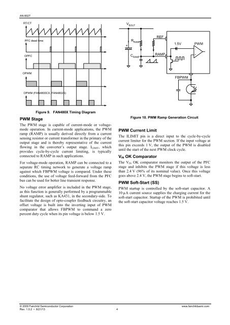
Figure 9. F<strong>AN</strong>480X Timing Diagram<br />
PWM Stage<br />
The PWM stage is capable of current-mode or voltagemode<br />
operation. In current-mode applications, the PWM<br />
ramp (RAMP) is usually derived directly from a current<br />
sensing resistor or current transformer in the primary of the<br />
output stage and is thereby representative of the current<br />
flowing in the converter’s output stage. ILIMIT, which<br />
provides cycle-by-cycle current limiting, is typically<br />
connected to RAMP in such applications.<br />
For voltage-mode operation, RAMP can be connected to a<br />
separate RC timing network to generate a voltage ramp<br />
against which FBPWM voltage is compared. Under these<br />
conditions, the use of voltage feed-forward from the PFC<br />
bus can be used for better line transient response.<br />
No voltage error amplifier is included in the PWM stage,<br />
as this function is generally performed by a programmable<br />
shunt regulator, such as KA431, in the secondary-side. To<br />
facilitate the design of opto-coupler feedback circuitry, an<br />
offset voltage is built into the inverting input of PWM<br />
comparator that allows FBPWM to command a zero<br />
percent duty cycle when its pin voltage is below 1.5 V.<br />
© 2009 Fairchild Semiconductor Corporation www.fairchildsemi.com<br />
Rev. 1.0.2 • 6/21/13 4<br />
V BOUT<br />
R RAMP<br />
C RAMP<br />
REF<br />
RAMP<br />
1.5V<br />
FBPWM<br />
Figure 10. PWM Ramp Generation Circuit<br />
PWM<br />
PWM Current Limit<br />
The ILIMIT pin is a direct input to the cycle-by-cycle<br />
current limiter for the PWM section. If the input voltage at<br />
this pin exceeds 1 V, the output of the PWM is disabled<br />
until the start of the next PWM clock cycle.<br />
VIN OK Comparator<br />
The VIN OK comparator monitors the output of the PFC<br />
stage and inhibits the PWM stage if this voltage is less<br />
than 2.4 V (96% of its nominal value). Once this voltage<br />
goes above 2.4 V, the PWM stage begins to soft-start.<br />
PWM Soft-Start (SS)<br />
PWM startup is controlled by the soft-start capacitor. A<br />
10 µA current source supplies the charging current for the<br />
soft-start capacitor. Startup of the PWM is prohibited until<br />
the soft-start capacitor voltage reaches 1.5 V.<br />
-<br />
+


