CMA Technical Manual - Love Coffee Machines
CMA Technical Manual - Love Coffee Machines
CMA Technical Manual - Love Coffee Machines

Create successful ePaper yourself
Turn your PDF publications into a flip-book with our unique Google optimized e-Paper software.
12 - English<br />
R<br />
espresso coffee machine - instructions for technician<br />
3.3 ELECTRICAL CONNECTION<br />
On the electrical mains, it is advisable to install a main protection switch (A)<br />
Machine with INTERNAL MOTOR PUMP<br />
Connect the power cable as set forth in the chapter “Electrical diagrams” (the cable has a<br />
cross-section and number of wires based on the power and voltage of the machine).<br />
Machine with EXTERNAL MOTOR PUMP<br />
1) Connect the cable to the motor pump (with lesser cross section) to the connector<br />
as shown in the diagram shown alongside.<br />
2) Connect the machine power cable (with greater cross section) as set forth in the<br />
chapter “Electrical diagrams”.<br />
WARNING<br />
Always connect the motor pump cable before the machine power supply cable, in accordance with the diagram provided.<br />
Failure to comply with the instructions given above may cause serious damage to the machine an/or to the motor pump<br />
and will invalidate any guarantee. Carry out all electrical connections with the power supply disconnected.<br />
3.4 GAS CONNECTION (if provided for)<br />
Install a pressure reducer upstream from the gas system. When operating on<br />
gas, the machine emits combustion fumes directly into the surroundings where<br />
it is being used. Therefore, gas-powered machines must not be installed in<br />
rooms with a volume of less than 12 m 3 , as described in standards UNI 7129<br />
and UNI 7131.<br />
On the pipe works upstream from the machine, a cut-off cock must be installed.<br />
If flexible hoses rather than stiff pipes are used for connections, they must be<br />
compliant with standard UNI 7140. These hoses must not be more than one<br />
metre long, and they must be firmly attached to the hose connection with a safety<br />
clamp (UNI 7141). They must not be placed near potential heat sources, they<br />
must not reach a temperature greater than 50°C, they must not be subjected<br />
to traction or twisting stress, and they must not have any kinks in them. It must<br />
be possible to inspect them along their entire length, and they must not come<br />
into contact with sharp objects or sharp corners.<br />
The machine is assembled with the methane gas nozzle already installed.<br />
The nozzle for city gas or gas cylinders is provided. Check that the nozzle<br />
is appropriate to the type of gas being used before lighting the burner. The<br />
incoming gas pipe must be equipped with a cut-off cock near the machine (see<br />
the provided gas diagram).<br />
At the cock outlet there will as necessary be installed a flexible hose or a stiff<br />
copper pipe. Pipe connections to the machine must be made in accordance with<br />
current standards in the country of installation. If connection is made with a<br />
flexible hose, first of all insert the hose into the gas safety hose connection.<br />
If instead you would like to make a stiff connection, you can use a soft copper<br />
pipe Ø6x8, equipped with a 1/4 gas nipple at the gas safety (remove the hose<br />
connection first).<br />
NOTE<br />
To adjust the gas system, refer to chapter12.<br />
The water in the boiler can be heated in various ways: only electrically (machines<br />
without gas system), only with gas (version AL - SMMA), with a combined<br />
system of gas and electricity (machines with gas system).<br />
5<br />
3<br />
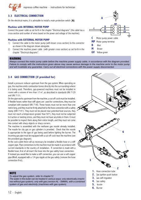
C<br />
A<br />
B<br />
M<br />
GV<br />
MP<br />
C Motor pump power cable<br />
MP Motor pump terminal<br />
B Blue<br />
M Brown<br />
GV Yellow-green<br />
2<br />
1. Hose connection tube<br />
2. Gas ignition push button<br />
3. Gas self-regulator<br />
4. Gas safety<br />
5. Nozzle<br />
6. Burner<br />
B<br />
M<br />
GV<br />
6<br />
1<br />
4