PIKO digital Manual - GbbKolejka
PIKO digital Manual - GbbKolejka
PIKO digital Manual - GbbKolejka

You also want an ePaper? Increase the reach of your titles
YUMPU automatically turns print PDFs into web optimized ePapers that Google loves.
<strong>PIKO</strong> <strong>digital</strong><br />
<strong>Manual</strong>
Getting off to a quick start :<br />
1. Connect the adapter and the Digi 1 as described on page 8 under "Connection and<br />
Operation".<br />
2. The locomotives in the start set have been allocated addresses, which are shown on<br />
the labels on the bottom of the locos together with the transmission channel for the<br />
<strong>PIKO</strong> Digi remote control.<br />
3. Put the loco on the track and note the address and transmission channel (see label on<br />
bottom of loco). To start the loco all you have to do is to press one of the keys "A" to<br />
"D" on the remote control corresponding to the transmission channel given on the bottom<br />
of the loco. Then you can regulate the speed directly by pressing the keys "+" or "-<br />
". If you press or while the model is in motion it does an emergency stop and<br />
changes direction. We recommend you practise this a few times to give you reliable<br />
control of the loco speed.<br />
4. If you want to run another loco with a different address (see label on the bottom of<br />
the loco) on your layout then proceed as follows:<br />
Stop the loco in operation and put the second loco on the rails. You can control this<br />
loco exactly like the first one by using the appropriate transmission channel keys channel<br />
"A" to "D". Please practise this a few times.<br />
If you want to run both locos then press the appropriate transmission channel key ("A"<br />
to "D") for the loco in question and regulate its speed and direction as described under<br />
point 3 above.<br />
That is the whole secret of <strong>digital</strong> control.<br />
Congratulations ! you have mastered it already!<br />
5. N.B.: if you have problems with running two locos e.g., if the two locos are heading<br />
for a collision, press the "Stop" key immediately.<br />
Remove one loco from the rails, then press the Stop key again and start again from the<br />
beginning as described above.<br />
If you press the Stop key for a second time before removing the locos from the rails<br />
theywill start moving again at the same speed and - the crash is inevitable.<br />
6. A better way to control the locos is as follows: to bring a loco to an emergency stop<br />
it is safer first to press the channel key "A" or "B" for the loco and then either or<br />
. This also stops the loco.<br />
You should practise this a few times.<br />
Engine drivers on the full-size railways aren't let loose on the passengers in the first five<br />
minutes either. It simply takes practice!.<br />
Enjoy your training - it's certain to be a success!<br />
2
First of all we should like to congratulate you on acquiringyour new <strong>PIKO</strong> Digital Start Set.<br />
You have taken a decisive step into the fascinating world of <strong>PIKO</strong> model railways.<br />
Since you have decided on a <strong>digital</strong> system, unquestionably the modern way for running<br />
model railways, we should like to help you with some information that is important<br />
for you and which will provide you with the basic knowledge necessary for using<br />
<strong>digital</strong> technology.<br />
You do not need to know anything about <strong>digital</strong> technology. Just as you don't need to<br />
know why your computer does what you want - or sometimes doesn‘t! At the beginning<br />
it is enough if the locos run the way you want and later, in a second step, you<br />
learn how to set the switches.<br />
It is a good idea to find a helpful dealer specialising in model railways who can advise<br />
you when it comes to extending your new <strong>PIKO</strong> layout and from whom you can purchase<br />
the extra <strong>PIKO</strong> products you need.<br />
But before we explain how to set up your layout, we should like to give you some<br />
general information.<br />
Analogue versus <strong>digital</strong><br />
A fundamental decision<br />
<strong>PIKO</strong> model railways give you lots of fun regardless of whether they are operated by<br />
the conventional adapter and controller or by <strong>digital</strong> controls.<br />
The conventional method of operating model railways is known as analogue technology.<br />
It provides endless possibilities for large and small layouts. At the same time it has<br />
the advantage of being very sturdy and, especially for beginners, it provides simple<br />
access to the functioning of electric models. It is neither outdated nor antiquated nor<br />
old-fashioned.<br />
Digital technology is a bit more complicated since it includes various control and receiver<br />
components. Owing to its potential complexity it necessarily requires more knowledge<br />
for its operation since the functions of the locos as well as many other accessories<br />
can be controlled separately. The essential advantage of <strong>digital</strong> technology is that it is<br />
possible to control several locomotives on one track at the same time.<br />
An analogue layout can be converted to a <strong>digital</strong> layout without difficulty. Rails, turnouts,<br />
locos and wagons can all be operated <strong>digital</strong>ly. However all the components to be<br />
controlled must be provided with a data receiver, known as a decoder. This converts the<br />
<strong>digital</strong> commands received into analogue current. Even on a <strong>digital</strong> layout the movements<br />
of the locos, turnouts and signals are made via analogue driven motors.<br />
Conversely operating a <strong>digital</strong> layout with analogue technology is also possible, but a<br />
fair amount of alteration to the wiring is needed and there is no point - <strong>digital</strong> is so<br />
much more versatile.<br />
This means that if a <strong>PIKO</strong> model rail enthusiast has decided on <strong>digital</strong> technology, he or<br />
she should if possible keep to this technology.<br />
3
Owing to its variety of control possibilities <strong>digital</strong> technology provides enormous enjoyment.<br />
You will learn a lot and if the layout is complcated and many trains are to run at<br />
the same time you can use a computer to control it - this is not always so simple but can<br />
be an enjoyable challenge.<br />
Analogue and <strong>digital</strong> technology - the fundamentals<br />
With analogue technology the speed of <strong>PIKO</strong> locos is controlled by the voltage (0 -<br />
14V). This is achieved by a controller such as the <strong>PIKO</strong> Speed control #55003 (speed control<br />
with mains adapter) or the transformer with speed regulator #55002.<br />
With this only one loco can be driven on a track at a time. If several locos are on the<br />
same track, they will all travel at the same speed. If the tracks are isolated from one<br />
another it is possible to drive several locos but it is then necessary to connect several<br />
speed controllers to the tracks with appropriate switching and separate speed controller<br />
for each of the locos that will be simultaneously moving.<br />
With <strong>digital</strong> technology the entire layout operates with the same voltage (14V). In<br />
order to control the individual locos a control centre is required which sends commands<br />
(<strong>digital</strong> data) to the locos via the rails. So that these commands have an effect in the<br />
locos each loco is fitted with a decoder, which receives the commands and converts<br />
them i.e. decodes them, hence the name decoder.<br />
Each loco is given an address. So that each loco knows when it is being ‘spoken to’,<br />
each command from the control centre must be preceded by the loco’s address.<br />
Provided the address is identical with the address of the loco it will know: ”watch out,<br />
this command is for me.” Then the command is decoded, the loco decoder converts the<br />
command to an analogue function and the loco moves faster, slower, switches on its<br />
lights, whistles or stops.<br />
Technical description: The control centre converts the voltage received from the mains<br />
adapter to direct current. This is transmitted to the rails via an inverter and associated<br />
electronic circuits at a frequency of 10 - 20 kHz.<br />
This high frequency current is converted by the loco decoder to analogue DC current<br />
tha powers the motor as soon as the relevant command arrives.<br />
4
<strong>PIKO</strong> Digi 1 - introduction<br />
To provide for an easy introduction to <strong>digital</strong> technology, <strong>PIKO</strong>, in cooperation with the<br />
firm Uhlenbrock, which has had experience for many years in the field of <strong>digital</strong>ly controlled<br />
model railways, has developed a <strong>digital</strong> system which is very simple to operate.<br />
This system which is based on the <strong>PIKO</strong> Digi 1 makes it easy for any <strong>PIKO</strong> model rail<br />
enthusiast to set up a <strong>digital</strong> layout in easy stages.<br />
The first element required is the <strong>PIKO</strong> Digi 1. This is the <strong>digital</strong> control unit for the <strong>PIKO</strong><br />
model rail layout. The <strong>PIKO</strong> Digi 1 takes over the control of the locos and other components<br />
on the model rail layout. In the first phase of construction just 2 - 3 locos can be<br />
driven at once since the mains adapter supplied with the <strong>PIKO</strong> Digi 1 only has enough<br />
capacity to operate 2 - 3 locos.<br />
If you want to extend the layout and run more than 2 locos at the same time the <strong>PIKO</strong><br />
Digi 1 can be supplemented by the <strong>PIKO</strong> Digi 2. But we will hear more of this later.<br />
If it is intended to build a very large layout to run more than 4 - 6 locos at the same<br />
time with a lot of turnouts operating simultaneously and with signals continually in<br />
operation, the modeller will need a power source with high capacity because the model<br />
rail layout will then need a great deal of current. This can be provided by the <strong>PIKO</strong> Digi<br />
Power Box.<br />
It goes without saying that in the next few years the <strong>PIKO</strong> <strong>digital</strong> system will be developed<br />
beyond these three basic elements to make it possible for model rail enthusiasts to<br />
keep upgrading their <strong>digital</strong> layouts. Apart from this it is possible at any stage of the<br />
construction to combine with the Uhlenbrock <strong>digital</strong> systems.<br />
The various levels of construction are shown in the following diagrams:<br />
<strong>PIKO</strong> Digi 1 with one rail circuit:<br />
After this the <strong>PIKO</strong> Digi 1 can be combined with one or two <strong>PIKO</strong> Digi 2 units:<br />
5
If it is desired to extend further, the <strong>PIKO</strong> Digi Power Box comes into play:<br />
6<br />
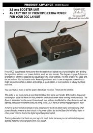
<strong>PIKO</strong> Digi 1 extended with <strong>PIKO</strong> Digi 2 and two isolated rail circuits:<br />
<strong>PIKO</strong> Digi 1 extended with two Digi 2 and three isolated rail circuits (maximal level of<br />
construction; 10 <strong>PIKO</strong> Digi 2):<br />
Desk Top Trafo T4<br />
72 VA<br />
isolating track connection<br />
isolating track connection isolating track connection<br />
Conversion to <strong>PIKO</strong> Digi Power Box<br />
isolating track connection isolating track connection
We should now like to explain how to operate the <strong>PIKO</strong> Digi 1, which will of necessity<br />
involve rather more technicalities.<br />
<strong>PIKO</strong> Digi 1 - the functions<br />
The <strong>PIKO</strong> Digi 1 is a <strong>digital</strong> control unit for model railways based on the DCC standard.<br />
The <strong>PIKO</strong> Digi 1 receives its power from the mains via a mains adapter (transformer)<br />
and transmits its commands to the locos via its connection to the track.<br />
The control of the locos themselves takes place exclusively via the infra red remote control,<br />
the <strong>PIKO</strong> Digi-fern (remote control) This transmits the commands to the <strong>PIKO</strong> Digi<br />
1, which sends them on in turn to the locos.<br />
This means: the control passes from the <strong>PIKO</strong> Digi remote control via the <strong>PIKO</strong> Digi 1 to<br />
the rails and from there to the loco containing the decoder. This then tells the engine:<br />
”go faster or slower.”<br />
Please note that the <strong>PIKO</strong> Digi remote control is only suitable for use indoors and that<br />
under favourable conditions it has a maximum range of about 10 metres.<br />
With the <strong>PIKO</strong> Digi remote control and the <strong>PIKO</strong> Digi 1 a maximum of 127 locos can be<br />
addressed on a <strong>digital</strong> layout and their direction of travel and speed as well as their<br />
other special functions controlled. In addition, with the two units, up to a maximum of<br />
256 switches, signals and other electromagnetic accessories can be operated.<br />
To make the <strong>PIKO</strong> Digi 1 more flexible in its use, the control system has 4 transmission<br />
channels which are marked on the <strong>PIKO</strong> Digi remote control with the keys A, B, C and<br />
D. You can store the address of a loco on each of these transmission channels so that it<br />
can be controlled when the transmission channel is called up. In addition besides the<br />
loco you can switch another 4 electromagnetic accessories via the same transmission<br />
channel.<br />
For instance, if channel A controls the loco with the address 15 and the accessories 1 to<br />
4, loco 20 can be controlled using channel B together with the accessories 13 to 16.<br />
Using these 4 transmission channels the modern railroader can switch rapidly from one<br />
loco to another. You can carry this even further. If you have several <strong>PIKO</strong> Digi fern<br />
remote control units and use them at the same time (up to 4) each <strong>PIKO</strong> modeler can<br />
control his own loco via one of the four transmission channels without affecting the<br />
locos of the other <strong>PIKO</strong> model train drivers.<br />
7
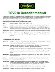
insert the adapter ➀ iinto the socket ➅.<br />
Connection and Operation<br />
The mains plug (mains adapter) ➀ is<br />
connected via the small plug ➁ to the<br />
socket in the <strong>PIKO</strong> Digi 1. The two connection<br />
leads marked "A" on the bottom<br />
of the <strong>PIKO</strong> Digi 1 are first fixed in<br />
the connecting clip ➂ by pressing the<br />
knobs ➃ and are then connected to the<br />
rails as follows:<br />
Insert the connecting clip ➂ into the<br />
rail ➄ (only this rail has slits between<br />
sleepers 5 and 7 for the clip). Now<br />
Please note: if you are using the <strong>PIKO</strong> Connecting Clip #55270 then the condenser in<br />
the clip MUST be removed. If the condenser is left in the Connecting Clip it will eliminate<br />
the high frequency control impulses and neither locos or accessories will work.<br />
Next the 4 batteries for the <strong>PIKO</strong> Digi remote control must be inserted into the battery<br />
compartment on the back as described.<br />
Batteries of the following types can be used: LR03-AAA-1.5V.<br />
8<br />
4<br />
3<br />
2<br />
4<br />
5<br />
G231<br />
6<br />
1
Now fit the adhesive pad to the base of the <strong>PIKO</strong> Digi 1. This will fix it to the model rail<br />
layout so that the <strong>PIKO</strong> Digi remote control can always be aimed at the <strong>PIKO</strong> Digi 1.<br />
There must be no obstacle between the <strong>PIKO</strong> Digi remote control and the <strong>PIKO</strong> Digi 1<br />
that could block the Digi remote’s infra red signals to the Digi 1.<br />
Digi 1<br />
Mountainous model<br />
Modellbahngelände<br />
rail mit layout<br />
Gebirge<br />
<strong>PIKO</strong> Digi-Fern<br />
<strong>PIKO</strong> Digi-Fern<br />
The <strong>PIKO</strong> Digi remote control works just like your TV remote control, which must to<br />
also be able "see" your television.<br />
For this reason when using the <strong>PIKO</strong> Digi remote control it should always be held pointing<br />
towards the <strong>PIKO</strong> Digi 1 and not towards the loco to be controlled.<br />
A red indicator LED under the transparent dome on the <strong>PIKO</strong> Digi 1 flashes when the<br />
receiver has received the infra red signal from the <strong>PIKO</strong> Digi remote control.<br />
Problem: no more current available or the locos stop running.<br />
If a short circuit occurs on the track or if the locomotives draw too much current from<br />
the track so that the <strong>PIKO</strong> Digi 1 or the mains adapter is overloaded then one or both<br />
units may shut down automatically. You will recognise this by the fact that the locomotives<br />
stop running.<br />
If the LED on the <strong>PIKO</strong> Digi 1 flashes then this unit has switched off:<br />
- the short circuit must be located and its cause removed or the current requirement for<br />
the locomotives reduced (e.g. by removing a loco from the track).<br />
- Switch the <strong>PIKO</strong> Digi 1 on again using the Stop key on the <strong>PIKO</strong> Digi remote control.<br />
Everything should now carry on normally.<br />
If the LED on the <strong>PIKO</strong> Digi 1 is not flashing, then the mains adapter has switched off:<br />
- the short circuit must be located and its cause removed or the current requirement for<br />
the locomotives reduced e.g. by removing a loco from the track<br />
- The mains adapter will switch itself on again after a short pause. It is not necessary to<br />
disconnect the mains adapter from the socket (230 V).<br />
Digi 1<br />
9
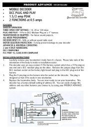
Using the <strong>PIKO</strong> Digi-fern remote control<br />
10<br />
red<br />
control LED shows the current activity<br />
in the <strong>PIKO</strong> Digi-fern remote control<br />
stop key to switch the track current<br />
on and off<br />
loco key to initiate selection of the<br />
loco address<br />
electromagnetic accessory key to<br />
initiate selection of the accessory<br />
address<br />
key to initiate programming a loco<br />
decoder<br />
to<br />
to<br />
key to increase the loco speed in steps<br />
key to reduce the loco speed in steps<br />
travel in reverse and emergency stop<br />
travel forwards and emergency stop<br />
special function switch lights on<br />
special function switch lights off<br />
keys for the special functions<br />
f1 to f4<br />
key to select special functions f5 to f8<br />
no function<br />
keys to switch accessories<br />
keys to select the<br />
transmission channel
1. Control LED<br />
As long as a key is being pressed on the <strong>PIKO</strong> Digi remote control, the remote control<br />
sends an infra red signal.<br />
This activity is shown by the control LED.<br />
2. Transmission channel<br />
The <strong>PIKO</strong> Digi 1 uses 4 transmission channels for the controls. The transmission signal can<br />
be altered at any time by pressing one of the keys .<br />
The address of a loco to be driven can be allocated to each transmission channel independently<br />
of the other channels.<br />
In addition, 4 individual variable addresses for electromagnetic components can be allocated<br />
in each channel to the 4 accessory keys. The addresses selected for each channel<br />
are not however stored permanently and are reset as follows when the Digi 1 has been<br />
switched off:<br />
When the power is switched on the channels are always allocated to the loco<br />
addresses 1, 2, 3 and 4 and the accessory keys in all channels control magnetic component<br />
addresses 1 to 4.<br />
Using the channel keys on the <strong>PIKO</strong> Digi remote control it is easy to change rapidly between<br />
controlling 4 locomotives and 4 groups each consisting of 4 accessories.<br />
If several <strong>PIKO</strong> Digi remote controls are used each <strong>PIKO</strong> Digi remote control can select a<br />
different transmission channel and so control an individual loco without affecting the<br />
loco driven from another <strong>PIKO</strong> Digi remote control using a different transmission channel.<br />
3. Loco control<br />
First of all the transmission channel A, B, C or D must be selected using the keys<br />
3.1. Entering the loco address<br />
A loco address must be selected.<br />
To select a loco address press the loco key The desired loco address can then be<br />
entered using the numerical keys 0 to 9<br />
The entry is concluded when any other key is pressed.<br />
This rule does not apply to the channel selection keys . For instance, the entry<br />
can be terminated by pressing the key for lights control or a key for altering the speed of<br />
the loco.<br />
If on the other hand the loco key , is pressed after the figures have been entered the<br />
selection mode is terminated without carrying out the command.<br />
The selection mode is also terminated if no input is made within 10 seconds.<br />
11
The address used as the loco address consists of the last (up to 3) digits entered provided<br />
this address is between 0 and 127. This means you can enter 8 digits if you like but<br />
the <strong>PIKO</strong> Digi remote control only retains the last three. If an invalid address is entered<br />
control remains with the previously selected locomotive.<br />
Examples:<br />
1.) input: [1] [f0]<br />
On the loco with address 1 the lights are switched on.<br />
2.) input: [6] [5] [4] [1] [2] [3] [+]<br />
The loco with the address 123 increases its speed.<br />
3.) input: [1] [2] [f0]<br />
The loco address of the channel remains unchanged and the lights on the previously<br />
selected loco are switched on.<br />
Reason: in this example the loco key functions like a delete key i.e. the digits entered<br />
are deleted when the loco key is pressed for the second time and the address entered<br />
is not valid.<br />
If the loco address 0 is selected control is directed to a conventional loco without <strong>digital</strong><br />
decoder - if there is one - on the <strong>digital</strong> circuit. Thus it is possible to drive a loco<br />
without decoder together with the locos fitted with decoders.<br />
N.B./Warning:<br />
If conventional locomotives without decoders are driven with the <strong>PIKO</strong> Digi 1 in <strong>digital</strong><br />
operation these locos make a low humming sound because the motor is continually<br />
supplied with high frequency current.<br />
This current can damage some engines e.g. bell-armature motors (Faulhaber, Escape etc)<br />
and small N motors. On <strong>digital</strong> layouts these motors should always be used with a <strong>digital</strong><br />
decoder.<br />
3.2. Speed control<br />
The speed of the loco is increased or decreased in steps with the keys or . If the<br />
keys are held down the speed is altered in steps until either the key is released again,<br />
the maximum speed is reached or the loco comes to a standstill.<br />
12
3.3. Selecting the direction of travel<br />
The direction of travel is selected using the keys or . With the key the loco is<br />
reversed and with the key it goes forwards. If one of the keys is pressed while the<br />
loco is already in motion, the loco is first brought to an emergency stop and then the<br />
chosen direction of travel started.<br />
3.4. Switching the loco lights on and off<br />
The lights on the loco are switched on with the key and off with the .<br />
3.5. Special functions<br />
The keys switch the special functions f1 to f4 on and off.<br />
If the dual function key is pressed and then one of the keys the special<br />
functions f5 to f8 are switched on or off.<br />
If after pressing the dual function key another key is pressed which is not a special function<br />
key then the process is broken off.<br />
4. Operating accessories<br />
Switches, signals and other items which carry out a function via an electromagnet or<br />
solenoid are known as electromagnetic components or accessories for short.<br />
Before an accessory address (using the red/green pairs of keys) can be entered the electromagnetic<br />
component key must first be pressed. Afterwards the desired accessory<br />
address can be entered using the numeric keys 0 to 9. The first address is always allocated<br />
to the outer left red/green pair of keys.<br />
The input is completed by pressing any other key with the exception of the channel<br />
selection keys A, B, C and D. For example, the input can be completed by pressing a red<br />
or green key or a key for controlling the loco.<br />
If on the other hand after entering the numbers the electromagnetic component key is<br />
pressed, then the selection mode is broken off without carrying out the command.<br />
The selection mode is also terminated if no input is made within 10 seconds of the last<br />
entry.<br />
The address used for accessories consists of the last (up to 3) digits entered provided<br />
this address is between 1 and 256. This means you can enter 8 digits if you like but the<br />
<strong>PIKO</strong> Digi remote control only retains the last three. If an invalid address is entered control<br />
remains with the previously selected magnetic component.<br />
Once the accessory addresses have been selected the components can be switched to<br />
round (red) or straight (green) using the red and green keys.<br />
The selected accessory address is always allocated to the outer left pair of keys. From<br />
here, towards the right, the remaining pairs of keys switch the accessories with the following<br />
higher addresses.<br />
13
Examples:<br />
1.) input: [1] [red1]<br />
The accessory with the address 1 is switched to red and the accessory keys from left to<br />
right switch the accessory addresses 1 to 4.<br />
2.) input: [6] [5] [1] [2] [3] [4] [red1]<br />
The accessory with the address 234 is switched to red and from left to right the accessory<br />
keys switch the components with the addresses 234 to 237.<br />
3.) input: [1] [2] [red1]<br />
The accessory address of the channel is not altered and the previously selected accessory<br />
is switched to red<br />
Reason: after the digits were entered the accessory key was pressed and this breaks off<br />
the input.<br />
5. Programming loco decoders<br />
Initial settings of the loco decoders<br />
The loco with the address "1" (see label underneath the loco) is controlled via transmission<br />
channel "A".<br />
The loco with the address "2" (see label underneath the loco) is controlled via transmission<br />
channel "B“.<br />
This can however be altered.<br />
Using the key a loco decoder can be allocated a different loco address.<br />
N.B.: When a loco is re-programmed only one loco should be on the track connected to<br />
the power supply. If several locos are on the track all the locos will be programmed to<br />
the same address.<br />
To programme the address first the key must be pressed twice. Then the desired<br />
loco address can be entered using the numeric keys 0 to 9. The address used as the loco<br />
address consists of the last (up to 3) digits entered provided these are within the range<br />
0 to 127. This means that you can enter 8 digits but the <strong>PIKO</strong> Digi remote control only<br />
retains the last 3 digits. If an invalid address is entered the programming process is not<br />
initiated.<br />
If the key is pressed again after the loco address has been entered the input is completed<br />
and the automatic programming process is started.<br />
14
Examples:<br />
1.) input: [1]<br />
Every loco on the track is programmed to address 1.<br />
2.) input: [5] [6] [1] [2] [3]<br />
Every loco on the track is programmed to address 123.<br />
3.) input: [5] [6] [2] [3]<br />
The programming process is not started because the last 3 digits are 623 and this is not<br />
a valid address between 0 and 127.<br />
Every loco which is programmed with the <strong>PIKO</strong> Digi 1 receives the loco address entered<br />
on the <strong>PIKO</strong> Digi remote control and is switched into the 28 speed mode.<br />
The 28 speed mode represents the levels of speed. This means that the speed is not altered<br />
continuously but in small steps. Since these cover the range from approx 2 V starting<br />
up current to a maximum of 14 V top speed current, with 28 steps there are so<br />
many tiny steps that these do not register as steps at all but seem like a continuous<br />
increase in the speed of travel.<br />
The voltage intervals of approx. 0.4V are so small that the modeller cannot tell that it is<br />
not a continuous process.<br />
Other features of the loco decoder cannot be programmed.<br />
It is not possible to read information from the loco decoder.<br />
This means that it is not possible to test which loco address has been allocated to the<br />
loco on the track. This does not matter, however since the loco or rather its decoder can<br />
easily be re-programmed with a new address at any time.<br />
6. Power on / off<br />
The current to the tracks on the layout can be switched on and off using the key.<br />
Note:<br />
If 10 seconds elapse in selection mode after the keys are pressed and no<br />
other key is pressed, the address input (i.e. loco address, switch address and programming<br />
address) is automatically ended. Now the selection mode must be re-started.<br />
The same applies to the dual function key . Here too if 10 seconds elapse after the<br />
key is operated and no other key is pressed the process is broken off.<br />
15
7. LED signals<br />
Track current switched on: LED permanently switched on<br />
Track current switched off: LED flashes slowly<br />
Short circuit at track exit: LED flashes quickly<br />
Loco being programmed: LED flashes twice briefly with longer pause<br />
Technical data<br />
• Data format: DCC with 28 loco speed levels<br />
• Loco addresses: 1-127, address 0 controls a loco without decoder on the <strong>digital</strong> circuit<br />
(i.e. a conventional loco)<br />
• Special loco functions: lights and f1-f8<br />
• Accessory addresses (turnouts, signals etc): 1-256<br />
• Refresh cycle: 12 locos<br />
Refresh cycle: if the power to a loco is interrupted for more than 1 second, the decoder<br />
switches to stop. Since this often happens on a layout, the data from the control centre<br />
is sent to the locos repeatedly all of the time that the loco is operating. This is called<br />
the refresh cycle. The <strong>PIKO</strong> Digi 1 refreshes a maximum of 12 locos. If more than 12<br />
locos are on the layout it can happen that a 13th loco suddenly comes to a standstill<br />
because it hasn't been refreshed. In this case it must be selected again and receive new<br />
commands.<br />
• Input voltage: from 12 V to 16V AC/DC<br />
(N.B.: none of the power sources must exceed 16 V. If several mains adapters or transformers<br />
are connected to the <strong>PIKO</strong> Digi 1 and the <strong>PIKO</strong> Digi 2, their voltages must be<br />
within the range 14 V to 16 V.)<br />
• Output current: max 1.8A<br />
• Max. power pickup: 28VA<br />
(N.B.: mains adapters or transformers of more than 45 VA capacity must not be connected<br />
to the <strong>PIKO</strong> Digi 1 or <strong>PIKO</strong> Digi 2. Doing so can lead to damage to the electronic<br />
components.)<br />
• Mains adapter included # 55010 in start sets : max 12 VA<br />
• T3 Desk top transformer included in the <strong>PIKO</strong> <strong>digital</strong> basic set, # 55005: max. 28 VA<br />
Maximum controllable locomotives: two<br />
As described above up to 127 locomotives can be controlled using the <strong>PIKO</strong> Digi 1.<br />
However, this does not mean that 127 locos can be driven using the mains adapter supplied with<br />
the <strong>PIKO</strong> Digi 1.<br />
Since each locomotive requires a certain amount of current, depending on its type between<br />
300mA and 400mA, and some locos under load (i.e. when pulling a long train) use a lot more, no<br />
16
more locos can be driven at one time than the mains adapter can supply with power. With the<br />
mains adapter #55010/NA max. 850mA, included in the start set this would be two locos averaging<br />
400mA.<br />
If more locos are put on the track and too much current is drawn this overloads the mains adapter<br />
which simply switches off. This is similar to a short circuit.<br />
Controlling more than 2 locomotives<br />
If you want to run more than two locos are to be driven on the layout then you must<br />
either<br />
• connect a more powerful transformer to the <strong>PIKO</strong> Digi 1<br />
• or connect extra mains adapters known as boosters to the model rail layout to provide<br />
additional power.<br />
N.B.: <strong>PIKO</strong> Digi 1 and <strong>PIKO</strong> Digi 2 must not be operated using mains adapters or transformers<br />
of more than 45 VA capacity. Doing so can cause damage to electronic components<br />
and the <strong>digital</strong> control could be permanently damaged.<br />
Higher capacity transformer for the <strong>PIKO</strong> Digi 1<br />
The <strong>PIKO</strong> T3 desk top transformer, #55005<br />
If you have a start set with a mains adapter plug for 850 mA power (# 55010) then you<br />
can also increase the supply to your <strong>digital</strong> layout by replacing the mains adapter with<br />
the <strong>PIKO</strong> T3 desk top transformer, # 55005. Using this T3 desk top transformer you can<br />
exploit the full range of the <strong>PIKO</strong> Digi 1.<br />
N.B.: Never connect 2 mains adapters in parallel to the same <strong>PIKO</strong> Digi 1 or to the same<br />
connection clip. This would destroy the <strong>PIKO</strong> Digi 1. Moreover, this parallel connection<br />
can result in an exceedingly dangerous high voltage current at the plug to the domestic<br />
power supply!<br />
With 16 V ~ output voltage the <strong>PIKO</strong> T3 desk top transformer produces a current of 28<br />
VA (1.75 A). This means that 4 locomotives with a power requirement of approx. 400<br />
mA each can be run on an electrically isolated track section.<br />
The <strong>PIKO</strong> T3 desk top transformer is connected to the <strong>PIKO</strong> Digi 1 just like the mains<br />
adapter (see section "Connection and Operation" above). All you have to do is to fit<br />
the connecting lead between the T3 desk top transformer and the <strong>PIKO</strong> Digi 1 (see<br />
Operating Instructions for the T3 desk top transformer).<br />
Additional booster<br />
The <strong>PIKO</strong> Digi 2<br />
To increase the power supply to a <strong>PIKO</strong> model rail layout still further i.e. in order to run<br />
more than 2 or 4 locos simultaneously, additional power supply units (transformers)<br />
must be connected.<br />
17
For this <strong>PIKO</strong> recommends the <strong>PIKO</strong> Digi 2 with the T3 desk top transformer. With 16 V<br />
~ output voltage the <strong>PIKO</strong> T3 desk top transformer produces a current of 28 VA (1.75<br />
A). This means that 4 locomotives with a power requirement of approx. 400 mA each<br />
can be run on an electrically isolated track section.<br />
on an electrically isolated track section.<br />
The T3 desk top transformer can supply current to electrically isolated track circuits<br />
through the <strong>PIKO</strong> Digi 2. Each T3 desk top transformer must be connected to a separate<br />
<strong>PIKO</strong> Digi 2. Using the T3 desk top transformer the maximum performance range of the<br />
<strong>PIKO</strong> Digi 2 can be utilised.<br />
In order for the <strong>digital</strong> data from the <strong>PIKO</strong> Digi 1 to reach the additional electrically isolated<br />
track sections, the <strong>PIKO</strong> Digi 1 must be connected to each of the <strong>PIKO</strong> Digi 2 units.<br />
To ensure that the strength of the signal sent by the <strong>PIKO</strong> Digi 1 is adequate no more<br />
than 10 <strong>PIKO</strong> Digi 2 units should be connected to one <strong>PIKO</strong> Digi 1. You should make<br />
sure that the length of the lead from each <strong>PIKO</strong> Digi 2 to the <strong>PIKO</strong> Digi 1 does not<br />
exceed 2 m.<br />
The <strong>PIKO</strong> Digi 2 is connected to the <strong>PIKO</strong> Digi 1 via the lead connected to the bottom of<br />
the <strong>PIKO</strong> Digi 2 at exit "B". This lead is connected in parallel to the <strong>PIKO</strong> Digi 1 connection<br />
at the connecting clip on the G231 track.<br />
Using a separate connecting clip the <strong>PIKO</strong> Digi 2 itself is then connected via the lead at<br />
exit "A" to the electrically isolated track section. (You can use the <strong>PIKO</strong> Digi 2 in combination<br />
with the T3 desk top transformer in the same way as a booster for the <strong>PIKO</strong> Digi<br />
Power Box. See diagram below.<br />
1<br />
2<br />
18<br />
T3<br />
G231<br />
4<br />
3<br />
5<br />
230V~, 50 Hz AC<br />
# 55291 isolating<br />
track connection<br />
# 55275 <strong>digital</strong><br />
connecting clip<br />
T3<br />
G231<br />
2<br />
2 2<br />
6<br />
Länge Length max. 2 2m m<br />
6<br />
Length Länge max. 2 2mm<br />
6<br />
3<br />
4<br />
1<br />
4<br />
2<br />
T3<br />
G231<br />
3 3<br />
230V~, 50 Hz AC 230V~, 50 Hz AC<br />
# 55021 connecting lead for<br />
Digi 1, Digi 2<br />
# 55005 desk top transformer T3<br />
input: 230 V~; output: 16 V~ 28 VA<br />
1<br />
5<br />
4<br />
a maximum of 10 Digi 2 units<br />
can be connected to Digi 1<br />
6 INPUT max.<br />
16 V / 45 VA AC/DC<br />
2
The locomotives used can be driven from one electrically isolated track section to another<br />
without any problems. They receive their control data from the <strong>PIKO</strong> Digi 1 which<br />
transmits the data via the <strong>PIKO</strong> Digi 2. Care must however be taken to ensure that the<br />
locomotives on a track section at any one time do not require more power than the<br />
relevant transformer can supply. Work on the basis of approx. 400 mA per loco. If the<br />
locos take up more power than the transformer can supply, it reacts like a short circuit<br />
and the <strong>PIKO</strong> Digi 1 or Digi 2 or the transformer switches off automatically.<br />
If the LED on the <strong>PIKO</strong> Digi 1 is flashing then the <strong>PIKO</strong> Digi 1 has switched off:<br />
- the cause of the short circuit must now be eliminated or the power requirement of<br />
the locomotives reduced (e.g. by removing a loco from the track)<br />
- The <strong>PIKO</strong> Digi 1 is then switched on again using the stop key on the <strong>PIKO</strong> Digi remote<br />
control. And now everything proceeds normally again.<br />
If the LED on the <strong>PIKO</strong> Digi 1 is not on and is not flashing, the mains adapter has switched<br />
off:<br />
- the cause of the short circuit must now be eliminated or the power requirement of<br />
the locomotives reduced (e.g. by removing a loco from the track)<br />
- The mains adapter will now switch on again after a short interval. It is not necessary<br />
to disconnect the mains adapter from the 230 V socket.<br />
N.B.: If you use the <strong>PIKO</strong> Digi 1 with the starter set adaptor (12 VA) and the <strong>PIKO</strong> Digi 2<br />
connected with the desk top transformer T3, # 55005 (28 VA) then a short circuit will<br />
occur when a train runs over the insulated rail joints (insulated rail joiners). No short circuit<br />
will occur if the <strong>digital</strong> connecting clips, #55275, are more than 1 metre apart.<br />
This is not required if you use the <strong>PIKO</strong> Digi 1 with the desk top transformer T3, # 55005<br />
(28 VA) and the <strong>PIKO</strong> Digi 2 with the adaptor, # 55010 (12 VA) or if both the <strong>PIKO</strong> Digi<br />
1 <strong>PIKO</strong> Digi 2 are operated with the Desk-Top Trafo T3, # 55005 (28 VA).<br />
The power peak<br />
The <strong>PIKO</strong> Digi Power Box<br />
The heights of <strong>digital</strong> control on a <strong>PIKO</strong> <strong>digital</strong> layout are reached using the <strong>PIKO</strong><br />
Power Box, the PPB for short.<br />
In combination with the T4 desk top transformer the PPB delivers 72 VA. After deduction<br />
of the PPB's own requirements 48 VA are available to run the locomotives (divided<br />
by 16 V = 3 A). This is enough to run 7 - 8 locomotives with a power requirement of 400<br />
mA per loco on a section of track served by the PPB and separated from other tracks (3<br />
A divided by 400 mA = approx. 7 - 8).<br />
The most varied operations can be carried out centrally from this control centre.<br />
The most important functions are summarised below:<br />
• Two separate speed controls to drive locomotives<br />
• Control for up to 9999 locos<br />
• Switching function for up to 2000 electromagnetic accessories (Points, switches or signals)<br />
• Switching for up to 48 rail routes each of which activates up to 10 electromagnetic<br />
accessories successively<br />
19
• Fine speed control (up to 128 steps)<br />
• 12 control functions: lighting, sound, etc (F1 to F12)<br />
• multiple traction with up to 4 locos<br />
• automatic switch-off in case of short circuit<br />
• bus system for further extensions using Loconet.<br />
Additional accessories can be incorporated using Loconet, such as manual controls, control<br />
panels, switching panels for electromagnetic accessories and rail routes, track in<br />
use signals, connecting modules for switching panels and the Uhlenbrock Lissy system<br />
for loco identification and automatic layout control.<br />
• Computer connection via the serial interface (com port) on your PC<br />
• DCC booster connection<br />
• Programmable track connector<br />
• Built-in receiver for the <strong>PIKO</strong> Digi remote control and connection for additional remote<br />
control receivers<br />
• Virtual loco addresses<br />
• Multilingual operating instructions<br />
• Compatible with NMRA-DCC<br />
• Updateable operating software<br />
This should be sufficient to give you a general picture. The PPB manual contains a full<br />
description or you can download the description from our <strong>PIKO</strong> home page<br />
www.piko.de.<br />
The <strong>PIKO</strong> <strong>digital</strong> basic set, # 55011<br />
If you have a conventional <strong>PIKO</strong> layout and would like to convert it to a <strong>digital</strong> layout,<br />
you can achieve this with the <strong>PIKO</strong> basic set.<br />
This contains all the elements required to convert your <strong>PIKO</strong> model rail layout to a <strong>digital</strong><br />
system:<br />
• <strong>PIKO</strong> Digi 1<br />
• T3 desk top transformer (#55005)<br />
• Connection lead from transformer to <strong>PIKO</strong> Digi 1 (# 55021)<br />
• <strong>PIKO</strong> Digi remote control (' 55012)<br />
• Connection clip (# 55275)<br />
• 2 <strong>PIKO</strong> loco decoders (# 56120) with loco addresses 1 and 2<br />
First install the decoder(s) in your <strong>PIKO</strong> locomotive(s). The separate operating instructions<br />
for the decoder contain a description. Please note the pre-allocated addresses at<br />
the decoder (see the label on the decoder) Unless you alter the addresses first, you need<br />
these addresses to control the locos!<br />
Now disconnect the power supply previously in use (transformer or mains adapter with<br />
speed control) from your model rail layout.<br />
20
N.B.: It may be possible for you to use your existing transformer as the power supply for<br />
your <strong>PIKO</strong> Digi 1 or <strong>PIKO</strong> Digi 2. For this it must deliver a constant voltage of 14 V to 16<br />
V AC or DC. The voltage must not fall below 14 V or exceed 16 V.<br />
Nor must the transformer have more than 45 VA capacity.<br />
At higher voltages the electronic components of the <strong>PIKO</strong> Digi 1 or <strong>PIKO</strong> Digi 2 may be<br />
permanently damaged!<br />
Now connect the <strong>PIKO</strong> Digi 1 to your model rail layout using the connection clip (only<br />
possible on G231 track) as described on page 8 above under the section "Connection<br />
and Operation".<br />
Now connect the <strong>PIKO</strong> Digi 1 to the T3 desk top transformer. To do this use the connecting<br />
lead with plug (# 55021). The installation of the lead is described in the separate<br />
operating instruction for the T3 desk top transformer.<br />
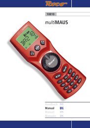
The following diagram shows the layout of the connections for the <strong>digital</strong> basic set:<br />
T3<br />
G231<br />
3<br />
230V~ 50Hz AC<br />
4 INPUT max. 16 V / 45 VA AC/DC<br />
Right, now you can get started!<br />
You can either begin as described on page 2 "Getting off to a quick start" or you can<br />
follow the detailed operating instructions on pages 4ff "<strong>PIKO</strong> Digi 1 - introduction".<br />
And now enjoy your <strong>PIKO</strong> <strong>digital</strong> system.<br />
Any other queries<br />
If you have any other questions about operating the <strong>PIKO</strong> digi1Digi 1 or <strong>PIKO</strong> Digi 2 or<br />
if anything doesn't seem to work then e-mail us at:<br />
hotline@piko.de<br />
Or call our hotline on a Thursday between 4 p.m. and 8 p.m.:<br />
0 36 75 / 89 72 42<br />
We shall all be happy to help you.<br />
And now we should like to wish you lots of fun and entertainment with your new <strong>PIKO</strong><br />
<strong>digital</strong> set.<br />
Yours<br />
The <strong>PIKO</strong> team<br />
2<br />
4<br />
1<br />
Legend:<br />
1<br />
2<br />
3<br />
# 55275<br />
<strong>digital</strong> connecting clip<br />
# 55021<br />
connecting lead for Digi 1/ Digi 2<br />
# 55005<br />
T3 desk top transformer T3<br />
input: 230 V~<br />
output: 16 V~ 28 VA<br />
21
Supplementary <strong>digital</strong> components from <strong>PIKO</strong>:<br />
22<br />
55011 <strong>PIKO</strong> <strong>digital</strong> basic set<br />
- <strong>PIKO</strong> Digi remote control<br />
- <strong>PIKO</strong> Digi 1<br />
- Desk top transformer 220V-, sec<br />
16V - 28VA<br />
- connecting clip<br />
- 2 <strong>PIKO</strong> loco decoders #56120<br />
- connecting lead for T3 desk top<br />
transformer<br />
55012 <strong>PIKO</strong> Digi 2<br />
- <strong>PIKO</strong> Digi 2<br />
- 4 connectors for isolation rails<br />
- connecting clip<br />
- connection lead for T3 desk top<br />
transformer<br />
55019 <strong>PIKO</strong> Digi-fern remote control<br />
- incl. 4 batteries<br />
55275 connecting clip for <strong>digital</strong> layouts<br />
connecting clip without EMV - suppressor essential for<br />
<strong>digital</strong> layouts fits G231<br />
55030 <strong>PIKO</strong> switch decoder for magnetic components<br />
Switch decoder to switch magnetic components via two independent<br />
addresses e.g. turnouts, signals, etc.<br />
55031 <strong>PIKO</strong> switch decoder for electric units<br />
Switch decoder for electric units via two independent addresses such<br />
as lamps, motors etc.<br />
55015 <strong>PIKO</strong> Digi power box<br />
control centre for a complex <strong>digital</strong> layout.<br />
55021 connection lead for Digi 1 / 2 to transformer<br />
If the T3 desktop transformer is to be used with the<br />
<strong>PIKO</strong> Digi 1 the lead with the low voltage plug #55021<br />
is required.<br />
55005 Desk top transformer T3 28VA<br />
Can be used to supply power to <strong>PIKO</strong> Digi 1<br />
and <strong>PIKO</strong> Digi 2<br />
Input :220V-<br />
Output: 16V-28VA<br />
55007 Desk top transformer T4 72VA<br />
Can be used to supply power to the <strong>PIKO</strong> Digi power box or<br />
as a lighting transformer<br />
input: 220Voutput:<br />
16V - 72 VA, with 4 connecting clips
Table of contents:<br />
Getting off to a quick start . . . . . . . . . . . . . . . . . . . . . . . . . . . . . . . . . . . . . . . . . . . . . . . . .2<br />
Analogue versus <strong>digital</strong> - a fundamental decision . . . . . . . . . . . . . . . . . . . . . . . . . . . . . . .3<br />
Analogue and <strong>digital</strong> technology - the fundamentals . . . . . . . . . . . . . . . . . . . . . . . . . . . .4<br />
<strong>PIKO</strong> Digi 1 - introduction . . . . . . . . . . . . . . . . . . . . . . . . . . . . . . . . . . . . . . . . . . . . . . . . . .5<br />
<strong>PIKO</strong> Digi 1 - the functions . . . . . . . . . . . . . . . . . . . . . . . . . . . . . . . . . . . . . . . . . . . . . . . . . .7<br />
Connection and operation . . . . . . . . . . . . . . . . . . . . . . . . . . . . . . . . . . . . . . . . . . . . . . . . . .8<br />
Using the <strong>PIKO</strong> Digi-fern remote control . . . . . . . . . . . . . . . . . . . . . . . . . . . . . . . . . . . . .10<br />
1. Control LED . . . . . . . . . . . . . . . . . . . . . . . . . . . . . . . . . . . . . . . . . . . . . . . . . . . . . . . . . . .11<br />
2. Transmission channel . . . . . . . . . . . . . . . . . . . . . . . . . . . . . . . . . . . . . . . . . . . . . . . . . . .11<br />
3. Loco control . . . . . . . . . . . . . . . . . . . . . . . . . . . . . . . . . . . . . . . . . . . . . . . . . . . . . . . . . . .11<br />
3.1. Entering the loco address . . . . . . . . . . . . . . . . . . . . . . . . . . . . . . . . . . . . . . . . . . . . . .11<br />
3.2. Speed control . . . . . . . . . . . . . . . . . . . . . . . . . . . . . . . . . . . . . . . . . . . . . . . . . . . . . . . .12<br />
3.3. Selecting the direction of travel . . . . . . . . . . . . . . . . . . . . . . . . . . . . . . . . . . . . . . . .13<br />
3.4. Switching the loco lighting on and off . . . . . . . . . . . . . . . . . . . . . . . . . . . . . . . . . . .13<br />
3.5. Special functions . . . . . . . . . . . . . . . . . . . . . . . . . . . . . . . . . . . . . . . . . . . . . . . . . . . . .13<br />
4. Operating accessories . . . . . . . . . . . . . . . . . . . . . . . . . . . . . . . . . . . . . . . . . . . . . . . . . . .13<br />
5. Programming loco decoders . . . . . . . . . . . . . . . . . . . . . . . . . . . . . . . . . . . . . . . . . . . . . .14<br />
6. Power on / off . . . . . . . . . . . . . . . . . . . . . . . . . . . . . . . . . . . . . . . . . . . . . . . . . . . . . . . . .15<br />
7. 7. LED signals . . . . . . . . . . . . . . . . . . . . . . . . . . . . . . . . . . . . . . . . . . . . . . . . . . . . . . . . . .16<br />
Technical data . . . . . . . . . . . . . . . . . . . . . . . . . . . . . . . . . . . . . . . . . . . . . . . . . . . . . . . . . . .16<br />
Maximum controllable locomotives . . . . . . . . . . . . . . . . . . . . . . . . . . . . . . . . . . . . . . . . .16<br />
Controlling more than 2 locomotives . . . . . . . . . . . . . . . . . . . . . . . . . . . . . . . . . . . . . . . .17<br />
Higher capacity transformer for the <strong>PIKO</strong> Digi 1<br />
The <strong>PIKO</strong> T3 desk top transformer, #55005 . . . . . . . . . . . . . . . . . . . . . . . . . . . . . . . . . . . .17<br />
Additional booster – The <strong>PIKO</strong> Digi 2 . . . . . . . . . . . . . . . . . . . . . . . . . . . . . . . . . . . . . . . .17<br />
The power peak – The <strong>PIKO</strong> Digi Power Box . . . . . . . . . . . . . . . . . . . . . . . . . . . . . . . . . .19<br />
The <strong>PIKO</strong> <strong>digital</strong> basic set, # 55011 . . . . . . . . . . . . . . . . . . . . . . . . . . . . . . . . . . . . . . . . . .20<br />
Any other queries . . . . . . . . . . . . . . . . . . . . . . . . . . . . . . . . . . . . . . . . . . . . . . . . . . . . . . . .21<br />
Supplementary <strong>digital</strong> components from <strong>PIKO</strong> . . . . . . . . . . . . . . . . . . . . . . . . . . . . . . . .22<br />
Owing to the inevitable continuous developments in <strong>digital</strong> technology we reserve all rights including those involving technical alterations<br />
and deliveries. No liability is assumed for the information given. Measurements and illustrations are subject to alteration.<br />
© 2005, <strong>PIKO</strong> Spielwaren GmbH<br />
23
<strong>PIKO</strong> Spielwaren GmbH · Lutherstr. 30 · 96505 Sonneberg<br />
Tel. 03675 897242 · e-mail: hotline@piko.de · www.piko.de<br />
© 2005 <strong>PIKO</strong> Spielwaren GmbH 55010-90-7001