SS-3 - Gaugemaster.com
SS-3 - Gaugemaster.com
SS-3 - Gaugemaster.com

Create successful ePaper yourself
Turn your PDF publications into a flip-book with our unique Google optimized e-Paper software.
GAUGEMASTER ®<br />
MODEL <strong>SS</strong>-3 AUTOMATIC OPERATING SYSTEM<br />
This unit is designed to allow two lo<strong>com</strong>otives to be run on one circuit of track yet not collide with one another due to different<br />
running speeds. This is ac<strong>com</strong>plished by dividing the track into five sections and connecting the unit in line between these and a<br />
controlled output. The system is then monitored by reed switches installed under the track at various points which are triggered by<br />
magnets under the lo<strong>com</strong>otives. The two lo<strong>com</strong>otives can then be run simultaneously, each only being able to proceed onto the<br />
following section when it is safe to do so. A soft start and stop have been incorporated to enhance the operation.<br />
There is also an optional facility to install two aspect colour light signals at each section.<br />
Bypass switches can also be added to allow lo<strong>com</strong>otives to be reversed in and out of sidings if desired.<br />
INSTALLATION<br />
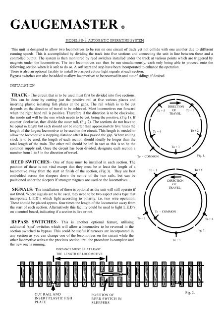
TRACK:- The circuit that is to be used must first be divided into five sections.<br />
This can be done by cutting just the positive rail at five various places and<br />
inserting plastic isolating fish plates at the gaps. The rail which is to be cut<br />
depends on the direction of travel to be achieved. Most lo<strong>com</strong>otives run forward<br />
when the right hand rail is positive. Therefore if the direction is to be clockwise,<br />
the inside rail will be the one which needs to be cut, being the positive, (Fig 1). If<br />
counter clockwise, then divide the outer rail, (Fig 2). The sections do not have to<br />
be equal in length but each should not be shorter than approximately five times the<br />
length of the largest lo<strong>com</strong>otive to be used on the circuit. This length is needed to<br />
allow the lo<strong>com</strong>otive a stopping distance after it has passed the gap. Where rolling<br />
stock is to be used, the length of each section should ideally be longer than the<br />
total length of the train. The other rail should be left in tact as this is to be the<br />
<strong>com</strong>mon supply rail. Once the circuit has been divided, designate each section a<br />
number from 1 to 5 in the direction of travel.<br />
REED SWITCHES:- One of these must be installed in each section. The<br />
position of these is not vital except that they must be at least the length of a<br />
lo<strong>com</strong>otive away from the start or finish of the section, (Fig 3). They are best<br />
embedded across the sleepers down the centre of the two rails, but can be<br />
positioned under the sleepers if stronger magnets are used on the lo<strong>com</strong>otives.<br />
SIGNALS:- The installation of these is optional as the unit will still operate if<br />
not fitted. Where signals are to be used, they need to be two aspect and a type that<br />
incorporate L.E.D’s which light according to polarity, i.e. two wire operation.<br />
These should be placed approx. four times the length of the lo<strong>com</strong>otive away from<br />
the start of each section. Alternatively this facility could be used to light L.E.D’s<br />
on a control board, indicating if a section is live or not.<br />
BYPA<strong>SS</strong> SWITCHES:- This is another optional feature, utilising<br />
additional ‘spst’ switches which will allow a lo<strong>com</strong>otive to be reversed in the<br />
section switched to bypass. This could be useful if turnouts are incorporated in<br />
any section as you can change one of the lo<strong>com</strong>otives on the circuit while the<br />
other lo<strong>com</strong>otive waits at the previous section until the procedure is <strong>com</strong>plete and<br />
the new one is running.<br />
CUT RAIL AND<br />
INSERT PLASTIC FISH<br />
PLATE<br />
DISTANCE MUST BE AT LEAST<br />
THE LENGTH OF LOCOMOTIVE<br />
POSITION OF<br />
REED SWITCH IN<br />
SLEEPERS<br />
To + 4<br />
To - COMMON<br />
To + 1<br />
To + 5<br />
DIRECTION<br />
OF<br />
TRAVEL<br />
To + 3<br />
DIRECTION<br />
OF<br />
TRAVEL<br />
To - COMMON<br />
To + 2 To + 4<br />
To + 3<br />
To + 1<br />
To + 2<br />
Fig. 3.<br />
Fig. 1.<br />
To + 5<br />
Fig. 2.
CONNECTING THE UNIT<br />
TRACK:- There will be six wires in total, i.e. one <strong>com</strong>mon and one from each section. Connect the <strong>com</strong>mon rail to terminal<br />
marked as such and each section according to its designated section number on the unit.<br />
REED SWITCHES:- Connect one side of each switch to the unit according to its designated section number. Connect the<br />
remaining side of each switch together to form a <strong>com</strong>mon and connect to terminal marked as such on unit. If signals are being<br />
installed do not connect to unit at this stage. (See signal check)<br />
SIGNALS:- Connect each signal to the unit according to the designated section number.<br />
BYPA<strong>SS</strong> SWITCHES:- Only the sections to be bypassed need to be connected to an ‘on - off ’ switch.<br />
CONTROLLER:- Connect the two wires from the controllers controlled output to the unit where marked. ‘12v DC input’.<br />
Polarity can be changed by direction switch if this is connected the wrong way. If it is the wrong way the circuit will simply remain<br />
dead, unless bypass switches are used and turned on.<br />
Connect the two terminals marked ‘16v AC input’ to a constant supply of 16v AC.<br />
SIGNAL CHECK:- When the 16v AC is turned on at this stage, all the signals should be showing green. If any show red, the<br />
two wires for that signal must be reversed. When all are showing green, the <strong>com</strong>mon wire from the reed switches can be connected to<br />
terminal marked as such on the unit.<br />
PREPARING THE LOCOMOTIVES<br />
Each lo<strong>com</strong>otive to be run on the circuit needs a magnet to be installed somewhere under the chassis in a position that enables it to<br />
pass closely over each of the reed switches.<br />
RUNNING THE CIRCUIT<br />
First ensure the unit is reset. This is done by removing the power from the 16v AC for a moment. When this is done, the signals if<br />
used will show green. With the controller set at zero, place the two lo<strong>com</strong>otives on two different sections with a clear section in<br />
between them. Increase the power on the controller and both of the lo<strong>com</strong>otives will start moving. If they do not, change the direction<br />
switch to the opposite direction. The circuit is now operational and the lo<strong>com</strong>otives should continue running and never meet. This is<br />
achieved as the section behind each train is switched off until the next one on is clear. The lo<strong>com</strong>otives will stop and start as required.<br />
GUARANTEE:<br />
We undertake to replace, free of charge, any parts found defective within the lifetime of the unit, providing the item has not been<br />
tampered with and parts are still available for such a repair. This guarantee covers only the supply of replacement parts, labour cost<br />
for fitting of the same and the cost of returning the unit to the customer or retailer.<br />
This Guarantee does not affect your statutory Rights.<br />
We reserve the right to vary design or specification without notice.<br />
A CATALOGUE ON THE FULL RANGE OF GAUGEMASTER PRODUCTS IS AVAILABLE<br />
GAUGEMASTER CONTROLS PLC Ford Road, Arundel, West Sussex, BN18 OBN.<br />
Tel. No: 01903 884321 Fax.No: 01903 884373<br />
Registered in England. Reg.No: 2714470.