DCC55 - Gaugemaster.com
DCC55 - Gaugemaster.com
DCC55 - Gaugemaster.com

You also want an ePaper? Increase the reach of your titles
YUMPU automatically turns print PDFs into web optimized ePapers that Google loves.
<strong>DCC55</strong><br />
GAUGEMASTER ®<br />
<strong>DCC55</strong> Prodigy Computer Interface<br />
Thank you for purchasing the Prodigy Computer Interface. It contains the hardware, (USB module) and<br />
<strong>com</strong>puter interface software. It will allow your <strong>com</strong>puter to function as a walkabout. It provides easier<br />
programming for your decoders, better management of your lo<strong>com</strong>otive inventory, consist settings, and<br />
route settings. Since the <strong>com</strong>puter interface software acts as a walkabout, you can use it with your<br />
Prodigy Advance, Prodigy Advance2, and Prodigy Wireless systems. By thinking of the <strong>com</strong>puter<br />
interface software as a walkabout it will help you in understanding its functions and its operation. You can<br />
carry over your knowledge of the Prodigy DCC systems and be<strong>com</strong>e familiar with the software in no time.<br />
Hardware Selection<br />
Cable version USB module (part <strong>DCC55</strong>) works with all Prodigy Advance systems.<br />
Installing the software<br />
Installing the software is easy. All you need to do is download the software and USB module drivers from<br />
our website (http://www.gaugemaster.<strong>com</strong>/instructions/prodigy/mrcdcc_1_1.exe ) and save them to your<br />
Desktop. Check back to our website for the latest version of the software. We will update the software<br />
and other documents periodically. If you are unable to access the Internet, you should ask your friend<br />
who can access the Internet to burn a CD for you. Or you can obtain a CD copy of the software and USB<br />
module drivers from us for a small charge.<br />
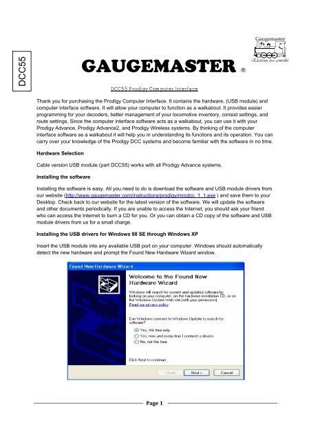
Installing the USB drivers for Windows 98 SE through Windows XP<br />
Insert the USB module into any available USB port on your <strong>com</strong>puter. Windows should automatically<br />
detect the new hardware and prompt the Found New Hardware Wizard window.<br />
Page 1
Please select “Yes, this time only” and click the Next button. The <strong>com</strong>puter will prompt the next<br />
window.There are two ways to locate the driver, either from the internet or from the CD. The driver will be<br />
installed twice. During these two installations you must select the same source for the driver. WARNING!<br />
If you select different sources, for example, first time using the internet and second time using<br />
CD, your installation will fail and makes your <strong>com</strong>puter unable to use the USB module.<br />
If you have access to the Internet you can select “Install the software automatically (Re<strong>com</strong>mended)” and<br />
click the Next button. The <strong>com</strong>puter will search online and install the driver for the device. This should<br />
take about a minute to 15 minutes (depends on your <strong>com</strong>puter and internet speed) for the <strong>com</strong>puter to<br />
search and install the driver. Please wait and do not unplug the USB module during the installation<br />
process. The installation process will repeat one more time before you are ready to use USB module.<br />
If you are unable to access the Internet, please select “Install from a list or specific location (Advanced)”<br />
and insert the CD that you ordered into your CD or DVD drive and click the Next button. You will see the<br />
following window:<br />
Page 2
Select “Search for the best driver in these locations” and “search removable media”. Windows will search<br />
the driver on the CD and install it for the USB module. Please do not unplug the USB module during the<br />
installation process. It will repeat the installation process once before you are ready to use USB module.<br />
Installation the USB drivers for Windows Vista:<br />
Insert the USB module into any available USB port on your <strong>com</strong>puter. Windows Vista<br />
should automatically detect the new hardware install the driver in a few seconds<br />
Operation of the Computer Interface software<br />
Double click on MRCDCC.exe that you downloaded from our website:<br />
http://www.gaugemaster.<strong>com</strong>/instructions/prodigy/mrcdcc_1_1.exe<br />
It will display the Cab # Setting dialog window.<br />
You need to assign an unique cab # as you do to the regular walkabouts. If you want to change the<br />
current cab # just type in the new number and click the OK button. Otherwise, just press the OK button to<br />
confirm the current cab #. Make sure that all of the cabs (walkabout) wired or wireless, have<br />
different cab numbers. Otherwise, the DCC system will not work properly. Also remember that<br />
Cab #1 is your Master Cab, no matter which type you are using.<br />
The main throttle operation window contains two independent throttles each with its own recall stacks. It<br />
also has four accessory controls, and three route controls. So you can control two lo<strong>com</strong>otives, four<br />
accessories and three routes all at the same time. The software is a standard windows application<br />
program. It contains labels, control buttons, and edit box. Before operating your layout, please spend a<br />
few minutes to explore the software. Try to click everything you see on the screen and see the response.<br />
You will learn how it operates in no time. When you close the main window it will automatically save<br />
current operation status into several data files in the same folder that MRCDCC.exe is located. These<br />
files contain the information such as cab number, lo<strong>com</strong>otive address, throttle settings, direction, consist,<br />
and route management. Do not edit or delete these files! Should you delete them by accident, you will<br />
lose the data from your last operation. If you run MRCDCC.exe on your desktop, all these data files will<br />
be appear on your desktop. If you don’t like too many data file’s icons on your desktop, you should keep<br />
MRCDCC.exe in the MRCDCC folder or in any other folder that you prefer. You can then run the software<br />
from the folder.<br />
Page 3
There are three ways to select a loco and operate it; type in the locos address in the address box, recall it<br />
from the recall stack, or set up a roster page and select the loco from the roster page. You can assign a<br />
road name (a description with road name and road number) to the loco along with its DCC address. This<br />
will enable you to run the loco by its road name. It is easier to remember the road name than to<br />
remember the address. When you select a lo<strong>com</strong>otive from the roster page it will pass the selected<br />
address and the road name to the throttle you select. This will also <strong>com</strong>bine the address and the road<br />
name and save them into the recall stack if the address is not in the recall stack. The address and the<br />
road name are separated by “-” sign. If the road name is too long only part of it will be displayed.<br />
Each recall stack can store up to 25 lo<strong>com</strong>otives. The recall stack is sorted by loco address. It cannot<br />
store two lo<strong>com</strong>otives with same address that have different road names. For example, if “3-xxxxxxxx” is<br />
already in the stack, it will not save another address 3 loco with different road name such as “3-yyyyyyy”<br />
in recall stack. If you really want to use “3-yyyyyyy” to replace “3-xxxxxxxx”, you have to delete “3xxxxxxxx”<br />
from stack first. To recall a lo<strong>com</strong>otive from the stack, select it and then click on the Recall<br />
button or you can just double click it. To delete a lo<strong>com</strong>otive from stack, select it and click Delete button.<br />
To add the current loco into the stack, press the Add button. Pressing the Speed Step button will let you<br />
select the desired speed steps (14/28/128) on the throttle. There are three ways to control the speed. You<br />
can move the throttle with your mouse. You can select the throttle by clicking on it and then you use the<br />
thumb wheel on your mouse. Or you can click “+1”, “-1”, “+5” or “-5” buttons. The button marked with<br />
“Forward” or “Reverse” is the direction control button. “Forward” indicates forward direction. Clicking it will<br />
change the direction and display. The Stop sign button is for the emergency stop.<br />
To turn off the track power, click the “TURN OFF track power” button. The button will change its display<br />
and flash to tell you that the power is off. Clicking the button again will restore track power. Clicking the<br />
F0 Light button will toggle the headlight function on and off. When the button turns yellow it indicates that<br />
the light is on. You can press the F2 button to control the horn sound. However, it is easier to use the<br />
Horn button to blast the horn or whistle. Functions 1 through 28 are all displayed for your convenience.<br />
Only functions 1 through 12 will indicate their on /off status. Yellow means on and grey means off.<br />
Page 4
Roster / Info Page: Click on the Roster / Info Page button to launch the Roster / Info Page window.<br />
From here you can set up the Roster / Info Page in such a way that it contains your entire lo<strong>com</strong>otive<br />
inventory including accessories. The Roster / Info Pages contain the DCC address, Road Name/Number,<br />
Lo<strong>com</strong>otive Type, and Special Notes. Once you set up the Roster / Info Page you can save it for later<br />
use. Click the “Save As” button to save it into a file. You can select which folder and which name to save<br />
the page. You can load the page later by pressing the OPEN File button. You can edit the page. You<br />
can save it by clicking the “Save” button. You can set up as many Roster / Info pages as you wish. To run<br />
a lo<strong>com</strong>otive from the Roster / Info Page just select the row that it is located. Then click on the “Use<br />
Throttle A” or “Use Throttle B” buttons. To operate accessory select the row that its address is located<br />
and click on “Use Acc A”, “Use Acc B”, “Use Acc C”, or “Use Acc D” button.<br />
Fast Clock Set Up: Click the Fast Clock button to launch the Fast Clock Setup window.<br />
This allows you to set the time, the rate, and to have it displayed in AM/PM or 24hr (Military).<br />
NOTE: Only Cab #1 can make the changes.<br />
The fast clock does not have anything to do with the clock found in the bottom right hand corner of your<br />
window taskbar. The fast clock is operated and sent to the walkabout by the base unit. Therefore all<br />
walkabouts can display the same time. The time rate is how many actual seconds are in one fast clock<br />
minute. Rate 1 means that one real second equals one fast clock minute, or 60 times as fast as real time.<br />
Rate 30 means 30 real seconds equal one fast clock minute, or twice as fast as real time. Rate 60 means<br />
60 real seconds equal one fast clock minute, or real time.<br />
Program a Decoder<br />
The Prodigy software provides two ways of programming your decoders: Easy Program and the CV<br />
Blaster. Clicking on the Easy Program button will launch the Easy Program window which allows you to<br />
program or read addresses. We designed this easy program for the user who does not want to bother<br />
with CVs and just wants to perform basic programming.<br />
Page 5
There are three sections in the Easy Program Window. The first section will let you select the program<br />
method. If you select the “Program on Main track” you have to know and enter the current lo<strong>com</strong>otive<br />
address. Without knowing the current lo<strong>com</strong>otive address you cannot perform programming on the main<br />
track. If your loco has lost its address you can not use “program main track” to reprogram its address to<br />
bring it to life. You have to program it on the program track. Make sure your lo<strong>com</strong>otive is on the main<br />
track before you perform “program on main track”. Also, make sure that your lo<strong>com</strong>otive is on the<br />
program track when you perform program or read on the Program track. The middle section will let you<br />
program or read an address. There are also three check boxes letting you to select how to operate the<br />
lo<strong>com</strong>otive. These settings will affect its CV29 value.<br />
• Checking “Enable Speed Table” box will enable the decoder to use its speed table to control the speed<br />
while operating at 28 speed steps. If you check this box you should use CV Blaster to program the speed<br />
table CV67 -CV94<br />
• Checking “Reverse Polarity” box will run the lo<strong>com</strong>otive in reverse, i.e. the loco runs in reverse while you<br />
<strong>com</strong>mand it to run forward, and runs in forward while you <strong>com</strong>mand it to run reverse.<br />
• Checking “Enable Analog” box will enable the lo<strong>com</strong>otive to operate on a DC track.<br />
To read back a lo<strong>com</strong>otive’s address, select “Read on Program track” and put the lo<strong>com</strong>otive on the<br />
program track and then click “Read Address” button. This may take a while to read the address. The last<br />
section allows you to read or program a CV. You can select to program Start Voltage, Acceleration Rate,<br />
Deceleration Rate, and Top Voltage. Enter their value and click on the Program button. If you want to<br />
program other CVs, select “All other CV”. The CV# box will display for you to enter CV#. To read back<br />
CVs, select “Read on Program track” and put the lo<strong>com</strong>otive on the program track. Select which CV to<br />
read and click “Read CV” button.<br />
Page 6
NOTE In order to read a decoder, the decoder itself must have the read back feature. Not all decoders<br />
support a read back CV feature. Consult the decoders’ manual to see if this feature is in your decoder<br />
before trying to read its CVs.<br />
CV Blaster Program: Click on the CV Blaster button to launch the CV Blaster window where you can<br />
program or read addresses and multiple CVs in one shot.<br />
There are three columns, each containing 15 rows of CV entries. You can read or program up to 45 CV’s<br />
in one shot. We re<strong>com</strong>mend you do not to include Speed Table CV67 to CV94 and Fxx Mapping CV33 to<br />
CV46 in the CV profile. They have their own special programming sections found at the top of this screen.<br />
If your decoder has more than 45 CVs you have to break them up into two CV profiles. The numbers 1<br />
through 15 on the left are row numbers only. They are also item numbers to indicate item #1 through item<br />
#15. We also mark “20” near item #20, “25” near item #25, and “30” near item #30 on second columns.<br />
These numbers have nothing to do with CV#. We put them there to help you count out how many CVs in<br />
your CV profile and. If you want to program/read partial CVs these item number can help you to figure out<br />
the starting item #. So you can skip some CVs. Please start with the left column when filling out the CV<br />
chart. The reading/ programming process starts with the address and then the left column. Continuing<br />
from row 1, row 2 and it will go down each row one by one. It will stop when it reaches a blank entry or<br />
CV #0. To program or read certain CVs, you can enter the start item# to tell it where to start.<br />
Page 7
And then begin the process. When it has finished the partial CVs you wanted, click on the Stop button to<br />
terminate the process. You have to enter in a CV number before you can program or read a decoder.<br />
Consult your decoders’ manual to get the CV chart (CV profile) for your decoder. Entering a CV that your<br />
decoder does not have will take longer for the Prodigy System to attempt reading back. This will be<br />
followed by a “fail” notification. You can set up your decoders’ CV profile by yourself or with your friends<br />
who have the same decoder. MRC will publish all of our decoders and some other brand decoders CV<br />
profiles online. We hope that you and your friends will help each other and help us to build a database for<br />
most decoders CV profiles and publish them online. You can load the CV profile, edit it and save it just<br />
like you do in the setup roster page.<br />
NOTE You can list CV1, CV7, CV8, CV17, CV18, CV19, and CV29 in your CV profile and read them.<br />
However, it will not program them to the value you enter because they are part of the address settings.<br />
The softwarewill automatically calculate and program their proper values according to the address you<br />
have entered.<br />
Program CV profile<br />
Select the program method and then click on the “Program” button. If you select program on main track<br />
you have to know and enter the current lo<strong>com</strong>otive address. Without knowing the current lo<strong>com</strong>otive<br />
address you cannot perform programming on the main track.<br />
Read CV profile<br />
Select Read on Program track and then click the “Read” button. Make sure to put your lo<strong>com</strong>otive on the<br />
program track when you are performing read on the program track.<br />
Program / Read Speed Table CV67 – CV94: Click the Speed Table CV67 - CV94 button on CV Blaster<br />
window to launch the Speed Table Program window.<br />
The 28 edit boxes from left to right are the values of CV67 to CV94. CV67 is for speed step 1. CV68 is for<br />
speed step 2… You can select several pre-defined speed curves such as one segment line, two segment<br />
lines, three segment lines, four segment lines, five segment lines, and Exponential curves from the drop<br />
down menu. Once you load the speed curve you can adjust the curve by clicking and dragging along the<br />
Page 8
lue guideline. CV67 to CV94 will change as you adjust the curve. You can also directly type in CV values<br />
if you wish. As you type in a number, the software will draw the graph on the screen. After you are done<br />
with the adjustment, select Program on Main track or Program on Program track to program in your speed<br />
table.<br />
Once you finish the speed table adjustment you can save it. You can load, edit and save it just like you do<br />
in setting up the roster page.<br />
You can also select “Read on Program track” and click the read button to read out your lo<strong>com</strong>otives<br />
speed table. Make sure you have your lo<strong>com</strong>otive on the program track before you click on the “Read”<br />
button.<br />
Function Mapping: Click Fxx Mapping CV33 - CV46 button on the CV Blaster window and it will launch<br />
the Function Mapping window.<br />
The Function Mapping allows you to assign your decoder’s function outputs to different function buttons.<br />
Each function has a CV assigned and tells it which function outputs to be controlled by it. Each function<br />
button can be programmed to control up to 8 outputs. There is a row of eight check boxes on the right<br />
side of each function. They represent 8 function outputs that can be assigned to that function. A checked<br />
box means its function output is controlled by the function. An unchecked box means it is not controlled<br />
by the function. For example, the above Fxx Mapping profile shows that Function F2 controls both output<br />
F1 and output F2. By programming CV36 to 12, function F2 will control output F1 and F2. This means<br />
when you blast the horn the bell will also ring. Function Mapping may not be available on some decoders.<br />
Check your decoder’s manual to see if you have Fxx mapping feature. The Function Mapping profile can<br />
also be loaded and saved.<br />
Page 9
Consist Manager: Click the Consist Manager button on the main window to launch the Consist Manager.<br />
Sometimes you will need more than one lo<strong>com</strong>otive to haul a heavy load. These grouped lo<strong>com</strong>otives are<br />
known as a double head or consist. The Prodigy software allows you to set up consists quickly and easily.<br />
This will also keep all consists in memory for easy consist management. Clicking the “Load History”<br />
button will display previous consist lists. Programming a lo<strong>com</strong>otive into consist actually programs the<br />
consist number into the lo<strong>com</strong>otives CV19. Whenever you program a non-zero value into CV19, CV19<br />
will then override the lo<strong>com</strong>otives original address to be<strong>com</strong>e the operational address.<br />
To setup or clear a consist, click the “Load History” button to display current consist history and then<br />
follow these steps. Make sure the locos to be setup are on the main track. You can do so by selecting<br />
them and operating them.<br />
1. Enter consist number (must be in the range of 1 to 127).<br />
2. Enter the lo<strong>com</strong>otive address to be added into consist.<br />
3. Select normal or reverse direction.<br />
4. Click the Add to Consist button.<br />
After clicking the “Add to Consist” button, it will program the consist number into the lo<strong>com</strong>otive’s CV19. It<br />
also create the consist list in consist history and add the lo<strong>com</strong>otive into the consist list. You can add<br />
more locos into consist by repeating step 2 to step 4. If you select reverse direction, a ® sign will be<br />
added after its address.<br />
The consist history list has two columns. The first column lists the consist # followed by “cons” sign. The<br />
second column repeats the first column and lists the lo<strong>com</strong>otive you have added into the consist. If you<br />
do not like the default format, you may use the Manual Edit in the top right corner to create your own<br />
description of the consist list. However, this will not program the lo<strong>com</strong>otives into CV19. We are not<br />
re<strong>com</strong>mending that you to use it. To clear a consist, enter the consist number, and click the Clear Consist<br />
Page<br />
10
utton. This will clear the lo<strong>com</strong>otive’s CV19. It will also remove it from the consist list. Make sure that<br />
your loco is on the main track. You can manually delete a consist list from the consist history. Select the<br />
list in the first column and click the Delete button. This will delete the list from the consist history.<br />
However, it will not program the locos CV19<br />
Once a consist has been setup, you can choose which throttle to run it on by selecting your consist from<br />
the first column, and then clicking on the Run on Throttle A or Run on Throttle B buttons. You may also<br />
type in the consist # into the address box on the main throttle window to operate it.<br />
Note: When you set up or clear consists please make sure that your lo<strong>com</strong>otive is on the main track. So<br />
the system can program the lo<strong>com</strong>otive while it updates the consist list. Otherwise, the list will not match<br />
your lo<strong>com</strong>otive’s consist settings and it be<strong>com</strong>es meaningless.<br />
For example, if you program lo<strong>com</strong>otive #3 into the consist #1, it will create a consist list and add<br />
lo<strong>com</strong>otive #3 into the list. The list tells you that lo<strong>com</strong>otive #3 is programmed with consist #1. The<br />
address #1 should be the operational address for the lo<strong>com</strong>otive #3, not its native address #3. You<br />
should use address #1 to control the lo<strong>com</strong>otive’s speed. But if you forget to put the lo<strong>com</strong>otive #3 on the<br />
main track when you setup the consist. The DCC system cannot program lo<strong>com</strong>otive’s CV19. So the<br />
lo<strong>com</strong>otive #3 will not respond to address #1. The consist list be<strong>com</strong>e meaningless and will cause<br />
confusion.<br />
Route Manager: Click the Route Manager button on the main window to launch the Route Manager.<br />
The route management is much like consist management, except that only the master cab (cab #1) can<br />
setup and clear routes. Route setup process does not involve any programming of accessory decoders. It<br />
programs the base unit. Once programmed, the base unit will memorize the settings. Make sure the<br />
Prodigy interface is connected to the base unit and the base unit is on while you set up or clear the route.<br />
Page<br />
11
Otherwise, the route list in route history will not match the settings in the base unit. The route lists will<br />
be<strong>com</strong>e meaningless.<br />
Note Only the master cab, cab #1 can setup a route. Before modifying an existing route, clear it first.<br />
Then re build it to eliminate potential errors. For example, if you want to set up route #4, clear the<br />
previous route #4 first. So there is no accessory in the route #4. Then you can add up to 8 accessories<br />
into the new route #4.<br />
If you believe your <strong>DCC55</strong> is faulty, please telephone us in the first instance. We will advise you of your<br />
best course of action. If it involves sending anything back, please send it to the address below via<br />
insured post and packed securely.<br />
POSTAL ADDRESS OTHER USEFUL CONTACT NUMBERS<br />
GAUGEMASTER Controls Ltd Telephone - 01903 884321<br />
<strong>Gaugemaster</strong> House Shop Sales - 01903 884488<br />
Ford Road, Arundel Fax - 01903 884377<br />
West Sussex E Mail - technical@gaugemaster.co.uk<br />
BN18 0BN<br />
Not suitable for children under 14 years unless supervised by an adult.<br />
Registered in England. Reg. No: 2714470.<br />
Page<br />
12