Rail-Built Buffer Stop - Gaugemaster.com
Rail-Built Buffer Stop - Gaugemaster.com
Rail-Built Buffer Stop - Gaugemaster.com

Create successful ePaper yourself
Turn your PDF publications into a flip-book with our unique Google optimized e-Paper software.
<strong>Rail</strong>-built buffer stops were used in all regions and areas<br />
and as with most of the basic infrastructure did not change<br />
with the grouping, the post WW2 formation of BR or even<br />
privatisation. While styles varied a little area by area, examples<br />
similar to this nominally M.R. styled buffer stop can<br />
still be found on sidings, in yards and on the edges of railway<br />
stations across the United Kingdom.<br />
Easy to install.<br />
When fixing in place, apply the glue sparingly. We<br />
think it is better to ally it to the rail to which the buffer<br />
stop will be secured and if you use only a little, it will<br />
be invisible. Use just enough to hold it in position.<br />
Bullhead rail: If using copper-clad based track, simply<br />
locate the buffer stop in the correct position and glue.<br />
If chaired, remove the chairs and after securing it, apply<br />
chairs split in half from each side.<br />
Flat-Bottom <strong>Rail</strong>: Code 75 and code 83 - Simply secure<br />
the <strong>Buffer</strong> stop in position. Code 100 may need the insides<br />
of each rail filing just a little to allow it so slip easily<br />
over the rail-head. Take your time and be careful, as<br />
this is a “dead scale” item and reasonably delicate.<br />
Easy to wire...<br />
The wire attached to the lamps is only 0.12mm thick so<br />
is easy to dress invisibly in the buffer stop.<br />
We re<strong>com</strong>mend you run it behind the cross-beam and<br />
down under and between the two rails. It can be securely<br />
held with superglue which works very well with<br />
both the lacquer on the wire and the polycarbonate of<br />
which the buffer-stop is made. Please do not use solvent<br />
based glues as they just may dissolve the insulating<br />
lacquer and create short circuits.<br />
Images & content of this manual are the intellectual property of DCCconcepts Pty Ltd<br />
Page 1/4<br />
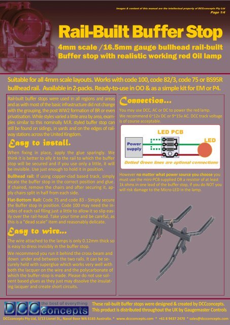
<strong>Rail</strong>-<strong>Built</strong> <strong>Buffer</strong> <strong>Stop</strong><br />
4mm scale /16.5mm gauge bullhead rail-built<br />
<strong>Buffer</strong> stop with realistic working red Oil lamp<br />
Suitable for all 4mm scale layouts. Works with code 100, code 82/3, code 75 or BS95R<br />
bullhead rail. Available in 2-packs. Ready-to-use in OO & as a simple kit for EM or P4.<br />
Connection…<br />
You may use DCC, AC or DC to power the red lamp.<br />
We re<strong>com</strong>mend 6~12v DC or 9~15v AC. DCC track voltage<br />
is of course acceptable.<br />
However no matter what power source you choose you<br />
must use the mini-PCB supplied OR a resistor of at least<br />
1k ohms in one lead of the buffer stop, if you do NOT you<br />
will risk damage to the Micro-LED in the lamp.<br />
These rail-built <strong>Buffer</strong> stops were designed & created by DCCconcepts.<br />
This product is distributed throughout the UK by <strong>Gaugemaster</strong> Controls<br />
DCCconcepts Pty Ltd, 3/13 Lionel St,, Naval Base WA 6165 Australia. * www.dccconcepts.<strong>com</strong> * +61 8 9437 2470 * sales@dccconcepts.<strong>com</strong>
1<br />
2<br />
3<br />
Images & content of this manual are the intellectual property of DCCconcepts Pty Ltd<br />
Page 2/4<br />
<strong>Rail</strong>-<strong>Built</strong> <strong>Buffer</strong> <strong>Stop</strong><br />
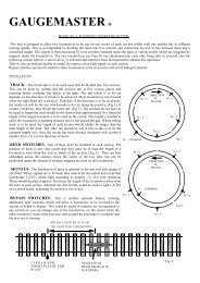
A Step by step installation and wiring guide<br />
I can be powered<br />
with AC, DC<br />
or DCC<br />
(6~15v)<br />
Simple Installation Instructions:<br />
(Please treat your <strong>Buffer</strong> stops gently - finer scale items can be fragile)<br />
Ballasting, painting/weathering of rails and basic buffer stop painting<br />
should be done before installation. We think final weathering is<br />
best done after installation - but that is up to you of course!<br />
STEP #1: If you are using chaired bullhead track, you’ll need to remove<br />
chairs to allow the horizontal parts of the buffer to sit properly. (split<br />
chairs and add back either side after installing).<br />
With flat-bottom code 75/83/100 track it will sit in place with no need<br />
to remove spikes or rail clips.<br />
Once the position for the buffer stop is prepared, drill a small hole inside<br />
the rail on the left side (Left when facing the buffer—see photo 1)<br />
STEP #2: carefully feed the wires through the hole. Put a small amount<br />
of glue (CA is fine) each side of the rail where the buffer stop will be<br />
fitted. (transfer with a pin, not from the tube). Ease the buffer stop into<br />
place so the rails are flush with the track railhead and squeeze gently<br />
for several seconds to secure in place.<br />
STEP #3: Mount the small PCB supplied with the buffer stops as shown<br />
in image#4 above. We used double sided tape but the screw hole<br />
(arrowed) will accept a #4 / 3mm screw if you prefer.<br />
The longer wire is Positive. Cut the wires to length, gently scrape away a<br />
little of the lacquer coating and solder them to the appropriate terminals<br />
of the PCB.. Solder the RH power supply wire to the small PCB and<br />
connect power. Watch the buffer stop light and then touch the second<br />
power supply light to each of the 3 resistor terminals. Make your choice<br />
of which light level you like then solder it in place.<br />
NOTE: LEDs are polarity sensitive—if it does not light, reverse the wires.<br />
These rail-built <strong>Buffer</strong> stops were designed & created by DCCconcepts.<br />
This product is distributed throughout the UK by <strong>Gaugemaster</strong> Controls<br />
DCCconcepts Pty Ltd, 3/13 Lionel St,, Naval Base WA 6165 Australia. * www.dccconcepts.<strong>com</strong> * +61 8 9437 2470 * sales@dccconcepts.<strong>com</strong><br />
4
Images & content of this manual are the intellectual property of DCCconcepts Pty Ltd<br />
Page 3/4<br />
<strong>Rail</strong>-<strong>Built</strong> <strong>Buffer</strong> <strong>Stop</strong><br />
4mm scale /16.5mm gauge bullhead rail-built<br />
<strong>Buffer</strong> stop with realistic working red Oil lamp<br />
Being a little creative - Using decoders to turn them on and off, vary the light level and<br />
even add in some interesting variety to add “micro detail” to your layout.<br />
Using a decoder to control things like our illuminated buffer stops can<br />
have some real advantages. It simplifies wiring and it is very, very economical<br />
as one 4 function loco decoder could give you control of<br />
quite a few buffer stops and a whole lot of yard lamps...<br />
Our suggestion.<br />
Here is our suggestion to control all non-railway items in a<br />
marshalling yard or loco facility using only one 4 function<br />
decoder: We use lots of loco decoders for things like lighting<br />
as it reduces wiring for a building with several independent<br />
light functions to just two wires attached to our accessory<br />
bus! We reserve decoder numbers in the 1 to 99 range for<br />
this kind of accessory use so its easy to manage.<br />
Motor control to any yard office chimney to control a<br />
smoke unit (or, if used to switch a relay, several of<br />
them could be controlled)<br />
Function 1 to yard building internal lights<br />
Function 2 to yard lamps & building exterior lights<br />
Function 3 to most buffer stops.<br />
Function 4 to just a couple of lamps... Dimmed right<br />
down and set to flicker like a lamp that is badly in need<br />
of oil or trimming of the wick)<br />
The above is for Steam era modellers... Modern image can<br />
be ac<strong>com</strong>modated too, as it is very easy to add flashing lights<br />
and strobes just by changing light function settings!<br />
Wiring it up is simple.<br />
The diagram printed on the next page will give you the basics<br />
of wiring accessories via a decoder and the drawings that<br />
make up the balance of this page, along with current draw<br />
estimates for several items that might be used will give information<br />
you need to do it for yourself.<br />
So... from now on, you can add a little “Interactive magic”<br />
to your layout any time you like, any way you like. You<br />
really are only limited by your imagination.<br />
Some tips for wiring:<br />
To remove the lacquer insulation from the fine wire<br />
scrape gently with a scalpel blade or use strong solvents<br />
such as acetone.<br />
The very fine copper wire is of course delicate so<br />
please secure the mini-PCB with a #4 wood screw (a<br />
hole has been provided) under the baseboard to prevent<br />
accidentally pulling on the wires.<br />
Consider using a 4 function decoder for a fan of sidings<br />
so they can be set up differently. Establish a light<br />
level by choosing the appropriate resistor, then adjust<br />
dimming on individual lamps with the decoder -<br />
you could even use “firebox flicker” to simulate a<br />
lamp that is badly in need of trimming!<br />
(See following page for example & wiring diagram)<br />
Calculating Accessory current draw:<br />
LED Values indicated are max with 1k or more resistor. The<br />
motor drive should not be loaded above 500mA for a constant<br />
load (it will handle more but will warm up if load for<br />
motor and all functions is on all of the time).<br />
Each of the 4 independently controllable active decoder<br />
functions can handle about 150mA (0.150 amps)<br />
Use the values below to calculate how many of any item a<br />
function can manage <strong>com</strong>fortably. If you wish to add a load<br />
higher than is “safe”, then you can use the function to<br />
switch a relay that will turn higher current items on and off.<br />
* DCCconcepts <strong>Buffer</strong> stops: 3mA (0.003 A)<br />
* DCCconcepts loco lamps: 3mA (0.003 A)<br />
* DCCconcepts Proto-white LED: 5mA (0.005 A)<br />
* Standard red LEDs 3mA (0.003 A)<br />
* DCCconcepts Station lamps 30~50Ma (0.05 A)<br />
(The actual value really depends on supply voltage)<br />
* Seuthe smoke Units (average) 120mA (0.12 A)<br />
(The actual value really depends on supply voltage)<br />
These rail-built <strong>Buffer</strong> stops were designed & created by DCCconcepts.<br />
This product is distributed throughout the UK by <strong>Gaugemaster</strong> Controls<br />
DCCconcepts Pty Ltd, 3/13 Lionel St,, Naval Base WA 6165 Australia. * www.dccconcepts.<strong>com</strong> * +61 8 9437 2470 * sales@dccconcepts.<strong>com</strong>
Smoke powered by<br />
Motor Drive<br />
To<br />
DCC Track Power<br />
or<br />
DCC Accessory Bus<br />
Images & content of this manual are the intellectual property of DCCconcepts Pty Ltd<br />
Page 4/4<br />
<strong>Rail</strong>-<strong>Built</strong> <strong>Buffer</strong> <strong>Stop</strong><br />
Add some creativity to layout lighting control.<br />
Using a decoder makes it very simple indeed !<br />
Building Lights<br />
F1 / White wire<br />
DCCconcepts<br />
4 function<br />
Decoder<br />
Resistor<br />
Yard Lamps<br />
F2 / Yellow wire<br />
Resistor<br />
<strong>Buffer</strong> stop with<br />
dim lamp / flicker<br />
F3 / green<br />
Resistor<br />
Bring Life to your layout with<br />
light and the simple addition<br />
of a standard 4 function loco<br />
decoder as the switch and<br />
“Special Effects” controller<br />
These rail-built <strong>Buffer</strong> stops were designed & created by DCCconcepts.<br />
This product is distributed throughout the UK by <strong>Gaugemaster</strong> Controls<br />
DCCconcepts Pty Ltd, 3/13 Lionel St,, Naval Base WA 6165 Australia. * www.dccconcepts.<strong>com</strong> * +61 8 9437 2470 * sales@dccconcepts.<strong>com</strong><br />
Resistor<br />
Yard Lamps with steady<br />
Lamps F4/ Purple wire<br />
Choose the decoder address - Then use these CV Settings for this example:<br />
For MOTOR DRIVE:<br />
To give quicker reaction when turned on, and still give you adjustment<br />
of smoke - try CV2 to 100, CV6 to 180 & CV5 to 250<br />
For WHITE Wire: (F0 will turn it on)<br />
To give constant light set CV49 to 32. (Start with resistor at 1k<br />
ohms / Adjust resistor value if you want to change light levels)<br />
For YELLOW Wire: (F0 will turn lamps on)<br />
To give constant light set CV50 to 32. (Resistor will depend on<br />
current draw. For DCCconcepts lamps use supplied resistance)<br />
For GREEN Wire: (F1 will turn it on)<br />
For random flicker set CV51 to 33. For a lower level experiment<br />
with resistors / small control PCB provided with the buffer stop.<br />
For PURPLE Wire: (F2 will turn it on)<br />
For steady light , you can leave CV setting as is (CV52 = 32)<br />
Use the small control PCB provided please.<br />
NOTES: For <strong>com</strong>prehensive setting advice in a really easy to read<br />
format use our Decoder Instruction cards - 52 colour coded cards<br />
that explain it all in simple and easy to understand language,<br />
… Installation to tuning, function mapping & troubleshooting.