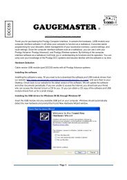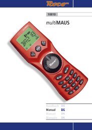
(DCC02) manual - Gaugemaster.com
(DCC02) manual - Gaugemaster.com
(DCC02) manual - Gaugemaster.com

Create successful ePaper yourself
Turn your PDF publications into a flip-book with our unique Google optimized e-Paper software.
PRODIGY ADVANCE 2<br />
New Prodigy Advance″ items have retained all the features of the<br />
standard Prodigy Advance system with the addition of F28 (28<br />
loco functions) <strong>com</strong>patible. To operate the loco functions you<br />
must use the keys marked 0 – 9 as stated in the <strong>manual</strong>, functions<br />
11 – 28 will require the SHIFT key to be pressed before the desired<br />
function number in full. As on all units the LCD screen will<br />
only display up to F12. Both Prodigy systems are fully <strong>com</strong>patible<br />
with each other but only when both walkabout and base unit<br />
have the PRODIGY ADVANCE ″ logo will the full 28 functions<br />
be accessible. In the event of either item not carrying this logo<br />
the system will default to the standard 20 functions. Up to twenty<br />
-five loco addresses can be held in the walkabout memory but if<br />
only two are entered it will default to one, if this happens a third<br />
loco address should be entered. This notice supersedes all other<br />
instructions in regards to this system
GAUGEMASTER<br />
PRODIGY ADVANCE<br />
USER MANUAL<br />
AUTUMN 2005 - Version 1.2 - E & OE
All these dioramas were built by Nick<br />
Duxfield (Sales Manager for<br />
GAUGEMASTER) using<br />
GAUGEMASTER scenic material<br />
GAUGEMASTER<br />
Scenic Products<br />
“Model Railway Solutions”<br />
Trees<br />
Scatters<br />
Flock<br />
Foliage<br />
Lichens<br />
Grasses<br />
Mod-roc<br />
Ballast<br />
Sea Foam<br />
Leaves<br />
Scenic Mats<br />
Cork Roll<br />
Underlay<br />
Track Pins
THANK YOU FOR CHOOSING PRODIGY ADVANCE<br />
Here at GAUGEMASTER,<br />
we have been manufacturing<br />
model railway controllers for<br />
around 30 years and without<br />
being big-headed, feel that<br />
our reputation for top quality<br />
controllers is well-deserved<br />
and justified. In life, things<br />
evolve and technology offers<br />
us new opportunities to try<br />
things that were previously<br />
impossible or at least<br />
prohibitively difficult. Who’d<br />
have thought when we<br />
began making model railway<br />
controllers that in around 30<br />
years time, almost all of us<br />
would own mobile<br />
telephones, digital cameras,<br />
personal <strong>com</strong>puters and have<br />
over 200 TV channels to<br />
choose from via the medium<br />
of satellite broadcasting. And that’s before we even mention the internet - possibly the<br />
greatest and most accessible resource there is. That is not to say that older technology is no<br />
good, we know many photographers who prefer to use conventional film over digital - it’s<br />
just the new opportunities that technology offers that makes it so exciting and that is how we<br />
feel about DIGITAL COMMAND CONTROL. It’s the opportunity to run your railway, the way<br />
you want rather than within the constraints of traditional operation - a new perspective on<br />
the operation of model railways. PRODIGY ADVANCE is “Quality in Digital Control”.<br />
Imagine, for example - a diesel depot with an array of lo<strong>com</strong>otives “on shed”. This layout is<br />
powered by PRODIGY ADVANCE. No doubt you will have a few questions.<br />
Q. How do I physically drive my trains?<br />
A. On the WALKAROUND<br />
Q. How many isolating sections are there?<br />
A. None. With DCC, you simply select your lo<strong>com</strong>otive, drive it to where you want and<br />
then select another lo<strong>com</strong>otive<br />
Q. Where is my point control panel?<br />
A. There isn’t one. Everything you need is on your WALKAROUND.<br />
Q. How do I separate my Up and Down Running Lines?<br />
A. No need. You drive the trains where you want on your layout<br />
You’ve noticed the capabilities of PRODIGY ADVANCE in the context of a small depot layout.<br />
Can you imagine the possibilities on a larger layout? You’re going to have a lot of fun.<br />
GAUGEMASTER - The UK Home of Prodigy Advance 3
4<br />
8<br />
YOUR PRODIGY ADVANCE SYSTEM<br />
Your Prodigy Advance DCC System includes the<br />
following:<br />
1. Power Pack<br />
2. Base Unit<br />
3. Walkaround Controller with LCD screen<br />
4. Leads for Power Pack and Controller<br />
PRODIGY ADVANCE - POWER SUPPLY AND BASE UNIT<br />
10<br />
2 3 7 4 6 5<br />
9<br />
1. Power supply – 15v DC at 3.5 amps.<br />
2. WALKAROUND select switch – Used to select from “1<br />
to 8 WALKAROUNDS” or “All WALKAROUNDS” (1-99).<br />
3. “Factory use only” socket – For factory use only at this<br />
time and will be used for future upgrades. Do not insert<br />
foreign objects into this port. Inadvertently plugging a<br />
WALKAROUND into this port will not damage the system,<br />
although the WALKAROUND will not function.<br />
4. WALKAROUND sockets (three) – Plug up to three<br />
WALKAROUNDS or use these ports to expand to a<br />
network of additional WALKAROUND extension plates<br />
around the layout. Up to 99 WALKAROUNDS can be used<br />
in a network.<br />
5. Power on/off switch – Turns BASE UNIT power on/off.<br />
6. Power light – Glows when system is on.<br />
7. Link light – Flashes during transmission of program<br />
data from the WALKAROUND to the BASE UNIT. This lets<br />
you know the BASE UNITS is receiving and accepting<br />
data. The light remains off at all other times.<br />
8. Cooling fan – Does not operate all the time and will<br />
only <strong>com</strong>e on during times of heavy load on the layout.<br />
9. Terminal plug output to main layout track and program<br />
track<br />
10. 15v DC input from POWER PACK<br />
Note Prodigy Advance does not support NON-decoder<br />
equipped analogue locos.<br />
GAUGEMASTER - The UK Home of Prodigy Advance<br />
1
PRODIGY ADVANCE - WALKAROUND<br />
1<br />
11 1. Function display – Large, easy to read LCD screen.<br />
Lets you monitor current loco address in use, functions<br />
2<br />
12 in use for that address, fast clock display, loco speed<br />
and direction. Also displays all programming features<br />
3<br />
13 in program mode and accessory decoder setup and<br />
programming.<br />
4<br />
14 2. Select LOCO button – Used to select a loco or consist<br />
5<br />
15<br />
address.<br />
3. DBL HEAD button – Used to set up double heading/<br />
6<br />
16 multiple unit operation (also known as Consists), add<br />
locos to double heads and clear double heading.<br />
7<br />
17 4. Function buttons – Allow you to select decoder<br />
functions.<br />
8<br />
18 5. -1 or DEL button – Dual function button that allows<br />
you to delete locos from the stack; and when running<br />
9<br />
19<br />
a current loco, allows you to Incrementally decrease<br />
the loco speed.<br />
10<br />
the speed control.<br />
A stack is a group of locos stored in your<br />
WALKAROUND memory. Each WALKAROUND can store<br />
up to 25 different loco addresses in its stack. Tap or<br />
press the -1 button quickly to decrease the loco speed.<br />
Holding the button for more than 2<br />
seconds will delete the current loco from the stack.<br />
6. TIME button – Allows you to view fast clock time<br />
while running current loco address. Press again to shut<br />
off time display. (The time is stored in the base unit, all<br />
Cabs see the same time).<br />
7. SPD STEP button – Used to synchronize the knob to<br />
programmed speed step (14/28/128) of decoder<br />
currently in use. Prodigy Advance Automatically<br />
programs all decoders to 28/128 speed steps. Speed<br />
steps are incremental steps that the decoder takes to<br />
go from 0 m.p.h. to full speed with the use of the<br />
WALKAROUND control knob. The higher number of<br />
speed steps programmed into the decoder, the finer<br />
8. Emergency STOP button – Press this button for 2 seconds to stop the Main Track output. To restore the Main Track<br />
output, press and hold STOP for 2 seconds again.<br />
9. WALKAROUND lead – Connects the WALKAROUND to the BASE UNIT<br />
10. LCD Screen (see Function display feature number 1 above)<br />
11. Select ROUTE button – Used to set Routes through pointwork when points are powered by accessory decoders<br />
and accessing the programmed Route in run mode.<br />
12. Select ACCESSORY button – Used to program accessory decoders as well as selecting accessory decoders when<br />
in run mode.<br />
13. PROG button – Used to program locos, accessory decoders and read values in decoders.<br />
14. SYS button – Used to change WALKAROUND system parameters or settings.<br />
15. +1 or ENTER button – Dual function button that allows you to lock in selections and information during<br />
programming process. When running a current loco, allows you to incrementally increase the loco speed.<br />
16. RECALL button – Allows you to scroll through the loco stack to select a loco address to run.<br />
17. SHIFT button – Used to access decoder functions higher than function #9. For example, if you want to access<br />
function 12, press SHIFT and 2 button to turn on/off function #12.<br />
18. DIRECTION button – Changes direction of current loco address.<br />
19. WALKAROUND controller knob – Used to adjust the speed of the current loco. When used in the “Yard” Cab<br />
mode, it can also reverse the direction of the current loco. The controller knob may be referred to as a<br />
potentiometer, pot or as an encoder - these are names of the parts used to make a controller knob. Prodigy Advance<br />
uses an encoder instead of a pot.<br />
GAUGEMASTER - The UK Home of Prodigy Advance<br />
5
TABLE OF CONTENTS<br />
1 GETTING STARTED<br />
1.1 Introduction<br />
1.2 DCC Basic Background<br />
1.3 Specifications & Features<br />
1.4 System Menu Summary Chart<br />
2 OPERATION<br />
2.1 Quick Start<br />
Connecting to your Layout<br />
Running a Lo<strong>com</strong>otive<br />
Controlling Accessory Functions<br />
Recalling Lo<strong>com</strong>otives<br />
Deleting Lo<strong>com</strong>otives<br />
Emergency Stopping<br />
Speed Steps<br />
Yard Mode On/Off<br />
Fast Clock<br />
Cooling Fan<br />
Overload and Short Circuit<br />
Shutting Down the Unit<br />
2.2 WALKAROUND Set-up<br />
Setting WALKAROUND Addresses<br />
Setting the Total Number of Operational WALKAROUNDS (WALKAROUND #1)<br />
Adding More than 3 WALKAROUNDS<br />
Setting Last WALKAROUND Allowed to Program Lo<strong>com</strong>otives on the Main Track (WALKAROUND #1)<br />
Setting Last WALKAROUND Allowed to Program Lo<strong>com</strong>otives on the Program Track (WALKAROUND #1)<br />
2.3 Programming Decoders<br />
2.4 Programming Lo<strong>com</strong>otives on the Program Track<br />
2.5 Programming Lo<strong>com</strong>otives on the Main Track<br />
2.6 Reading Lo<strong>com</strong>otive’s Decoder Values on the Program Track<br />
2.7 Configuration Variables - (CV’s)<br />
Most Commonly Used CV’s<br />
CV29<br />
2.8 Consisting (Also Known as DOUBLE HEADING)<br />
Advanced Consisting<br />
Programming Advanced Consists<br />
Running Advanced Consists<br />
Clearing Advanced Consists<br />
Universal (Old Style) Consisting<br />
Programming Universal (Old Style) Consists<br />
Running Universal (Old Style) Consists<br />
Clearing Universal (Old Style) Consists<br />
2.9 Fast Clock<br />
Setting Fast Clock (WALKAROUND #1)<br />
Setting Time (WALKAROUND #1)<br />
Setting Time Ratio (WALKAROUND #1)<br />
Setting AM/PM or 24 Hour Time (WALKAROUND #1)<br />
2.10 Reverse Loop<br />
2.11 Accessory Decoders<br />
Programming Accessory Decoders with CV #513<br />
Selecting Accessory Decoders<br />
2.12 Accessory Routes<br />
Setting Accessory Decoder Routes (WALKAROUND #1)<br />
Running Accessory Routes<br />
Clearing Accessory Routes<br />
2.13 Points<br />
3. TROUBLE SHOOTING<br />
3.1 General Trouble Shooting<br />
3.2 Checklist for General Problems<br />
3.3 More on Programming Lo<strong>com</strong>otive Addresses on the Program or Main Track & Decoder Read Back<br />
4. SERVICE AND SUPPORT<br />
5. GLOSSARY<br />
6. THE GAUGEMASTER PRODUCT RANGE<br />
6<br />
GAUGEMASTER - The UK Home of Prodigy Advance
1. GETTING STARTED - AN INTRODUCTION<br />
Thank you for buying the PRODIGY ADVANCE DCC (Digital Command Control) system. This is<br />
one of the most easy to use DCC systems available and has been designed by the Model<br />
Rectifier Corporation in America. Rather than re-invent the wheel, we at<br />
GAUGEMASTER were soon convinced that PRODIGY ADVANCE best met the needs of the<br />
UK modeller. Very soon you will realise you have chosen the right system.<br />
PRODIGY ADVANCE <strong>com</strong>es with a BASE UNIT, a POWER PACK and a WALKAROUND<br />
controller which will enhance the enjoyment of your Model Railway for many years to <strong>com</strong>e.<br />
This system has been designed to give you advanced, reliable and easy to use DCC control<br />
with 9,999 addresses available and use of up to 99 WALKAROUNDS, this is a system that<br />
caters for almost any model railway, from the smallest of shunting layouts to the biggest<br />
main line model railways. You will notice that there are brief bullet point style instructions<br />
on the back of the WALKAROUND unit. These have been designed more as a reminder than<br />
as <strong>com</strong>plete instructions. Please read these instructions fully to understand and enjoy all the<br />
features of PRODIGY ADVANCE<br />
DCC BASIC BACKGROUND INFORMATION<br />
DCC stands for DIGITAL COMMAND CONTROL. A typical system consists of a BASE UNIT that<br />
sends DCC <strong>com</strong>mands to your layout, and DCC decoders installed in your lo<strong>com</strong>otives which<br />
receive the DCC <strong>com</strong>mands. Each decoder-equipped lo<strong>com</strong>otive has it’s own address. Each<br />
decoder receives DCC <strong>com</strong>mands but only follows those <strong>com</strong>mands matching it’s own<br />
address. It really is that simple - no more cab control, no more isolating sections and much<br />
less wiring. With DCC, you can run different lo<strong>com</strong>otives at different speeds anywhere on<br />
your layout and all on the same track if you wish! You can turn the lo<strong>com</strong>otive’s headlight<br />
on and off and even activate sounds if your lo<strong>com</strong>otives are suitably equipped. By reading<br />
this <strong>manual</strong> fully you will soon have a good grasp of DCC control and will be able to enjoy<br />
the many benefits of the PRODIGY ADVANCE system.<br />
Please note that PRODIGY ADVANCE does not support NON-decoder fitted or analogue<br />
lo<strong>com</strong>otives. Some DCC systems do offer this facility but experience has taught us that this<br />
practice dramatically slows the response time of DCC systems. This was unacceptable to us<br />
and is why this facility is no longer offered.<br />
SPECIFICATIONS AND FEATURES<br />
INPUT—15-16v DC 3.5 amps<br />
OUTPUT - DCC Signal with 14.5v amplitude for OO/HO & N Scales<br />
MAXIMUM CURRENT - 3.5 amps<br />
MAXIMUM NUMBER OF WALKAROUNDS - up to 99<br />
ADDRESS CAPABILITY - 2 Digit (1-127) or 4 digit (1-9999)<br />
SPEED STEPS - 14/28/128<br />
ACCESSORY FUNCTIONS - 20 (F0 to F19)<br />
ADVANCED AND UNIVERSAL DOUBLE HEADING OR CONSISTING<br />
PROGRAMME LOCOMOTIVE ON PROGRAM TRACK<br />
PROGRAMME LOCOMOTIVE ON MAIN TRACK<br />
READ LOCOMOTIVE ON MAIN TRACK<br />
GAUGEMASTER - The UK Home of Prodigy Advance<br />
1<br />
7
KEYS FUNCTION<br />
SYS + 0 Clear Routes<br />
SYS + 1 Set Time<br />
SYS + 2 Set Time Ratio<br />
SYS + 3 Yard on/off<br />
SYSTEM MENU SUMMARY CHART<br />
Most functions are initiated by pressing their associated keys. However, there are ten<br />
functions activated by pressing the SYS key followed by a numeric key (0-9). The following<br />
table summarises these ten functions. Information about each function is found later on in<br />
this <strong>manual</strong>.<br />
SYS + 4 Set Time Mode (am/pm/24hr)<br />
SYS + 5 Set Routes<br />
SYS + 6 View Your WALKAROUND Address<br />
SYS + 7 Set Last WALKAROUND allowed to program locos on the main track<br />
SYS + 8 Set Last WALKAROUND allowed to program locos on the program track<br />
SYS + 9 Set total number of operational WALKAROUNDS<br />
2.1 OPERATION - QUICK START<br />
Connecting PRODIGY ADVANCE to your layout<br />
Follow the diagram to connect the BASE UNIT to your layout.<br />
1. Plug the POWER SUPPLY into the BASE UNIT.<br />
2. Plug the AC lead into your wall socket.<br />
3. Using a small flat-bladed screwdriver, attach two<br />
wires (0.643mm or heavier) from your Main Track<br />
layout (one from each rail) to the terminals marked<br />
“Main Track” and two wires from your Program<br />
Track to the terminals marked “Programming<br />
Track”.<br />
4. Plug one end of the cable into the<br />
WALKAROUND and the other into a “Controllers”<br />
socket on the BASE UNIT. Do not use the socket<br />
marked “Factory Use Only” as this is for potential<br />
future upgrades.<br />
5. Double check all wiring and then turn the power<br />
switch on the BASE UNIT to the “On” position. The<br />
power light should be on and you are now ready to<br />
run your Decoder Equipped lo<strong>com</strong>otives.<br />
8<br />
GAUGEMASTER - The UK Home of Prodigy Advance
Running a Lo<strong>com</strong>otive<br />
Firstly, turn the “Select Controller” switch on the BASE UNIT to “Ctlrs 1-8”. This will give you<br />
a faster response time. This is because the BASE UNIT will now only try to <strong>com</strong>municate with<br />
Controllers 1 to 8 and not 9 to 99. Naturally, this speeds things up a bit!<br />
To run a lo<strong>com</strong>otive, you must first establish it’s address. Most decoders you will buy have a<br />
factory default address of #3. If you buy a decoder equipped lo<strong>com</strong>otive, you may find that<br />
it’s running number or reference number is sometimes used. Consult your decoder or<br />
lo<strong>com</strong>otive instructions to find out what it’s decoder address is.<br />
To select a lo<strong>com</strong>otive, press the LOCO key on your WALKAROUND unit. Using the numeric<br />
keypad (0-9), enter the lo<strong>com</strong>otive’s address and press ENTER. You have just selected your<br />
lo<strong>com</strong>otive. The WALKAROUND controller will remember this address for later recall.<br />
Use the DIRECTION key to set the direction in which you want your lo<strong>com</strong>otive to travel.<br />
Turn the control knob slowly to increase the speed of the lo<strong>com</strong>otive. Your selected<br />
lo<strong>com</strong>otive will begin moving. Alternatively, you can tap +1 or –1 to adjust the speed. DO<br />
NOT, however, hold down the –1 key as this is also the DEL key and will delete the<br />
lo<strong>com</strong>otive’s address from the WALKAROUND and you will have to select it again. To toggle<br />
the headlight (F0) on and off, press 0.<br />
If you are using more than one WALKAROUND, you may notice a blinking lo<strong>com</strong>otive address<br />
on the screen. This indicates that another WALKAROUND is also controlling that lo<strong>com</strong>otive.<br />
However, you will find that the lo<strong>com</strong>otive will not move as you would expect it to as it will<br />
be receiving <strong>com</strong>mands from at least two different sources! Other operators should<br />
relinquish control of the lo<strong>com</strong>otive so you can control it properly from your WALKAROUND.<br />
Controlling Accessory Functions<br />
To control accessory functions F1-F9, press 1-9.<br />
To control F10-F19, press SHIFT then 0-9. When<br />
F1-F12 are on, F1-F12 will be displayed on the<br />
LCD. F13-F19 will not be displayed.<br />
Therefore the snapshot of an LCD WALKABOUT<br />
display on the left shows us that the current lo<strong>com</strong>otive<br />
is 3802, running in reverse at a speed of<br />
102 with accessory functions F1 and F11 being<br />
on.<br />
Recalling Lo<strong>com</strong>otives<br />
To call up previous lo<strong>com</strong>otives stored in the memory, press RECALL. You can recall up to 25<br />
lo<strong>com</strong>otives using this feature. Please note that although the WALKAROUND can store up to<br />
25 lo<strong>com</strong>otives, if it is unplugged from the BASE UNIT, it will only retain the last 4<br />
lo<strong>com</strong>otives used.<br />
Deleting Lo<strong>com</strong>otives<br />
The WALKAROUND can store up to 25 lo<strong>com</strong>otives. If you select a new lo<strong>com</strong>otive when the<br />
WALKAROUND is full, the new lo<strong>com</strong>otive will replace the current lo<strong>com</strong>otive which will be<br />
GAUGEMASTER - The UK Home of Prodigy Advance<br />
9
lost. To prevent this, we re<strong>com</strong>mend that you recall unused lo<strong>com</strong>otives and delete them by<br />
pressing and holding DEL for 2 seconds. This then creates capacity to store new lo<strong>com</strong>otives.<br />
Emergency Stopping<br />
For emergency stopping of the current lo<strong>com</strong>otive, press STOP. Pressing and holding STOP<br />
for 2 seconds will stop the Main Track output. The 2 lights on the BASE UNIT will blink. To<br />
restore the Main Track output, press and hold STOP for 2 seconds again.<br />
Speed Steps<br />
Speed steps are incremental steps the lo<strong>com</strong>otive takes to go from 0 to top speed. There are<br />
3 speed steps: 14, 28 and 128. The higher the speed step setting, the higher the number of<br />
different speeds on which the lo<strong>com</strong>otive can operate. When you enter a new lo<strong>com</strong>otive<br />
address (an address that has not been stored in the WALKABOUT memory), PRODIGY<br />
ADVANCE will set 28 speed steps as the default setting for that address. In order to make the<br />
most of the performance of your lo<strong>com</strong>otive, you may need to change the speed steps<br />
setting to match those of the decoder inside the lo<strong>com</strong>otive.<br />
To select other speed steps settings press SPD STEP repeatedly until you see your desired<br />
speed steps setting and then press ENTER. The selected speed steps setting will apply only to<br />
that address.<br />
Please remember that use of the SPD STEP button will NOT alter the speed step originally<br />
programmed into the decoder. It only matches the control knob to the decoder.<br />
Yard Mode On/Off<br />
To toggle the Yard Mode feature on or off, press SYS and 3. In standard control mode, the<br />
control knob only controls lo<strong>com</strong>otive speed. When the Yard Mode feature is on, with “Yard”<br />
displayed on the LCD screen on the WALKAROUND, the control knob will control the speed<br />
and direction of the lo<strong>com</strong>otives - like some existing analogue controllers where 12 o’clock is<br />
Stop with directional movement either side.<br />
Fast Clock<br />
To view the Fast Clock, press TIME. The time will<br />
replace the address display on the LCD. You can<br />
still run the current lo<strong>com</strong>otive while the time is<br />
displayed. To return to the standard lo<strong>com</strong>otive<br />
address display, press TIME again. The time<br />
information is stored in the BASE UNIT and<br />
transmitted to the WALKAROUND with each<br />
attached WALKAROUND displaying the same time.<br />
The diagram to your left shows a time of 8.02am<br />
with the current lo<strong>com</strong>otive moving forward at a<br />
speed of 102.<br />
Cooling Fan<br />
The Cooling Fan does not operate all the time, only activating during heavy loads.<br />
10<br />
GAUGEMASTER - The UK Home of Prodigy Advance
Overload and Short Circuit<br />
The BASE UNIT is rated at 3.5amps. Only you will know how many lo<strong>com</strong>otives and<br />
accessories can be run on the layout at the same time without triggering the circuit breaker.<br />
If there is an overload or short circuit, the BASE UNIT will stop the Main Track output for 2<br />
seconds and then resume. The fan will activate (spinning slowly) and may <strong>com</strong>e on and off<br />
periodically. To resume satisfactory operation, you must remove the subject of the overload<br />
or short circuit. Using a separate 16v AC supply (eg, a GAUGEMASTER M1) to power your<br />
accessories optimises the power available for running your lo<strong>com</strong>otives. Solenoid motors,<br />
buildings and coach lighting are heavy consumers of power. The Accessory Decoder<br />
instructions explain how to connect a GAUGEMASTER M1 to your Accessory Decoders.<br />
Shutting Down the Unit<br />
Please turn the power switch to the “Off” position before unplugging the POWER PACK from<br />
the AC outlet. This will then allow the BASE UNIT to store all current running information,<br />
including time, for your next operating session.<br />
2.2 OPERATION - WALKAROUND SET UP<br />
Setting WALKAROUND ADDRESSES<br />
You can use up to 99 WALKAROUND units with the PRODIGY ADVANCE. Each WALKAROUND<br />
must have a unique address. Any WALKAROUND that you buy will have a factory default<br />
address of #1. WALKAROUND #1 is the master unit that can perform all functions. Any<br />
additional WALKAROUNDS will also be<strong>com</strong>e master units, so must have their addresses<br />
changed from #1 to unique addresses.<br />
To view your WALKAROUND address, press SYS and 6. The current WALKAROUND address<br />
will momentarily display. If you would like to change you WALKAROUND address, type in a<br />
new address (between 1 and 99) followed by ENTER. Otherwise, press ENTER to exit.<br />
Remember not to duplicate WALKAROUND addresses.<br />
Setting the Total Number of Operational WALKAROUNDS (Master WALKAROUND only)<br />
The more WALKAROUNDS that are in use at any one time, the slower the system responds<br />
from WALKAROUND to lo<strong>com</strong>otive because the BASE UNIT can only <strong>com</strong>municate with one<br />
WALKAROUND at a time.<br />
To set the total number of operational WALKAROUNDS, please follow this procedure -<br />
1. Make sure that your WALKAROUND is the master unit (#1) as only the master unit can<br />
set the number of cabs allowed to operate on your DCC layout.<br />
2. Turn the “Select Controller” switch on the BASE UNIT to the “ALL CTRLS” position. The<br />
switch must be in this position to limit the number of WALKAROUNDS.<br />
3. Press SYS and 9<br />
4. Using 0-9, enter the address of the last operational WALKAROUND and then press<br />
ENTER.<br />
For example, if you use 10 WALKAROUNDS and program the WALKAROUND addresses #1 to<br />
#10, pressing SYS, 9, 10 and then ENTER - you will set the last operational WALKAROUND to<br />
10 and the BASE UNIT will not spend any time trying to <strong>com</strong>municate with WALKAROUNDS<br />
#11 to #99.<br />
GAUGEMASTER - The UK Home of Prodigy Advance 11<br />
9
If you use 3 WALKAROUNDS and program the WALKAROUND addresses #1 to #3, pressing SYS,<br />
9, 3 and then ENTER - you will set the last operational WALKAROUND to 3, with the BASE UNIT<br />
To optimise performance further, if you are using eight WALKAROUNDS or less, set all<br />
WALKAROUND addresses sequentially starting from #1 and turn the “Controller Select” switch<br />
on the BASE UNIT to the “CTLRS 1-8” position. This means that the BASE UNIT will no longer<br />
try and <strong>com</strong>municate to any WALKAROUNDS that may have addresses higher than 8.<br />
Adding More Than 3 WALKAROUNDS<br />
The BASE UNIT of the PRODIGY ADVANCE has 3 sockets for up to 3 WALKAROUNDS to plug<br />
into. If you want to use more than 3 WALKAROUNDS or would like to install WALKAROUND<br />
sockets around your layout then this can easily be achieved by the use of PRODIGY ADVANCE<br />
EXTENSION PLATES which are available from your dealer. The BASE UNIT is able to supply<br />
power to 6 WALKAROUNDS.<br />
Setting Last WALKAROUND Allowed to Program Lo<strong>com</strong>otives on the MAIN Track<br />
This feature prevents other operators from mistakenly reprogramming everything on your<br />
layout.<br />
To achieve this, please follow this procedure -<br />
1. Make sure your WALKAROUND is the master controller.<br />
2. Press SYS and 7.<br />
3. Using 0-9, enter the number of the last WALKAROUND allowed to program on the main<br />
track then press ENTER.<br />
For example, by pressing SYS, 7, 3 then ENTER - WALKAROUND #4 and above cannot program<br />
on your main track.<br />
Setting Last WALKAROUND Allowed to Program Lo<strong>com</strong>otives on the PROGRAM Track<br />
To achieve this, please follow this procedure -<br />
1. Make sure your WALKAROUND is the master controller.<br />
2. Press SYS and 8.<br />
3. Using 0-9, enter the number of the last WALKAROUND allowed to program on the<br />
Program Track then press ENTER.<br />
For example, by pressing SYS, 8, 2 then ENTER - WALKAROUND #3 and above cannot program<br />
on your Program Track.<br />
2.3 OPERATION - PROGRAMMING DECODERS<br />
The PRODIGY ADVANCE allows you to easily program most NMRA <strong>com</strong>patible decoders. It<br />
guides you step-by-step through the programming process. PRODIGY ADVANCE prides itself<br />
on simplicity of use - you do not need an engineering degree to program decoders with this<br />
system. PRODIGY ADVANCE allows you to program decoders on a separate Program Track or<br />
on the Main Track layout, all without affecting any other lo<strong>com</strong>otives operating on the Main<br />
Track.<br />
A list of <strong>com</strong>mon decoder terminology can be found on the next page. It is re<strong>com</strong>mended<br />
12<br />
GAUGEMASTER - The UK Home of Prodigy Advance
that you familiarise yourself with this terminology, to further your DCC knowledge.<br />
LOCO ADDRESS<br />
The address is the number assigned to a decoder to identify the decoder.<br />
START VOLTAGE<br />
This is the voltage required to start the lo<strong>com</strong>otive’s motor and over<strong>com</strong>e its weight and friction<br />
to begin to make it move. You can program your lo<strong>com</strong>otive with a start voltage so that<br />
it will begin to move as soon as the control knob is turned.<br />
TOP VOLTAGE<br />
The top voltage (top speed) is the voltage (speed) at full throttle. The PRODIGY ADVANCE top<br />
end voltage is set for maximum output. If you are operating a shunter, you may want the top<br />
end voltage to be less than full output for a more realistic performance when at full throttle.<br />
ACCELERATION RATE<br />
This rate simulates the drag of a heavy load as the lo<strong>com</strong>otive speeds up, so when you increase<br />
the speed setting, the lo<strong>com</strong>otive will gradually increase its speed.<br />
DECELERATION RATE<br />
This rate simulates the momentum of a heavy load as the lo<strong>com</strong>otive slows down, so when<br />
you decrease the speed setting, the lo<strong>com</strong>otive will gradually decrease its speed.<br />
2.4 OPERATION - PROGRAMMING LOCOMOTIVES ON THE PROGRAM TRACK<br />
1. Make sure your WALKAROUND is allowed to program on the Program Track.<br />
2. Place the lo<strong>com</strong>otive on the Program Track. Press PROG to select “Prog Prog Track”<br />
and press ENTER.<br />
3. First, “Adr” will flash, prompting you to program the lo<strong>com</strong>otive address. Using 0-9,<br />
enter the lo<strong>com</strong>otive address followed by ENTER, or press ENTER to skip. Please note<br />
that if you are a beginner or only want to program the lo<strong>com</strong>otive address, you can<br />
stop now as this is now <strong>com</strong>plete. Put your lo<strong>com</strong>otive back on the Main Track and<br />
select the lo<strong>com</strong>otive by pressing LOCO, then enter the lo<strong>com</strong>otive address and press<br />
ENTER. Now you can run your lo<strong>com</strong>otive. If you would like to do more then read on!<br />
4. Next “SV” will flash, prompting you to enter the Start Voltage. Input the data then<br />
press ENTER.<br />
5. Next “Acc” will flash, prompting you to program the acceleration rate. Input the data<br />
then press ENTER.<br />
6. Next “dEc” will flash, prompting you to program the deceleration rate. Input the data<br />
then press ENTER.<br />
7. Next “TV” will flash, prompting you to program the top voltage. Input the data then<br />
press ENTER.<br />
8. Finally, “CV#” will flash, prompting you to program a CV (Configuration Variable). At<br />
this point you have already finished most of the decoder programming. You can stop<br />
programming here by pressing ENTER. PRODIGY ADVANCE allows you to enjoy operating<br />
your model railway without having to fully understand CV’s and how they work as<br />
we like to keep things as simple as possible.<br />
9. However, if you want to program a CV, enter a CV number and press ENTER. Input<br />
your CV data and press ENTER again. “CV#” will flash again, prompting you to program<br />
another CV. To skip this, press ENTER.<br />
GAUGEMASTER - The UK Home of Prodigy Advance<br />
13
Please note that programming a CV with incorrect data can cause your decoder to<br />
malfunction. Read the <strong>manual</strong> that <strong>com</strong>es with your decoder carefully before programming a<br />
CV. Also, be certain to read the Configuration Variables section on the next page before<br />
attempting to program a CV. This will enable you to have a better understanding of<br />
Configuration Variables.<br />
2.5 OPERATION - PROGRAMMING LOCOMOTIVES ON THE MAIN TRACK<br />
Programming on the Main Track can saves you the effort of moving a lo<strong>com</strong>otive to the<br />
Program track for programming. However, you have to know the lo<strong>com</strong>otive address in order<br />
to program on the Main Track, otherwise all programming will have to take place on the<br />
Program Track. Remember, not all decoders support the Program on Main Track feature so do<br />
check the instructions that came with your decoder to see whether this feature is supported.<br />
To program lo<strong>com</strong>otives on the main track, please follow this procedure -<br />
1. Make sure your WALKAROUND is allowed to program on the Main Track<br />
2. To program on the Main Track, press PROG to select “Prog Main Track” then press<br />
ENTER. The current lo<strong>com</strong>otive address will flash, prompting you to program the<br />
current lo<strong>com</strong>otive.<br />
3. To program the current lo<strong>com</strong>otive, press ENTER. To program another lo<strong>com</strong>otive,<br />
enter its address and press ENTER.<br />
4. The rest of the programming procedures are the same as “Programming Lo<strong>com</strong>otives<br />
on the Program Track” (above). We also re<strong>com</strong>mend that you bring your lo<strong>com</strong>otive to<br />
a stop before programming because if the moving lo<strong>com</strong>otive has a bad pick-up, it<br />
may fail to receive the program <strong>com</strong>mand, causing a malfunction.<br />
2.6 OPERATION - READING LOCOMOTIVE’S DECODER VALUES ON PROGRAM TRACK<br />
The PRODIGY ADVANCE DCC system gives you the ability to read back CV values of a decoder<br />
equipped lo<strong>com</strong>otive on the Program Track. This feature is useful if you do not remember the<br />
decoder address or what CV values your decoder has. Please note that not all decoders support<br />
this function and you will need to consult your decoder’s instructions to check whether<br />
this feature is supported.<br />
To read lo<strong>com</strong>otive’s decoder values on your Program Track, please follow this procedure -<br />
1. Place your lo<strong>com</strong>otive on the Program Track<br />
2. Press PROG to select “rEAd Prog Track” then press ENTER.<br />
3. First, “Adr” will flash, prompting you to read the lo<strong>com</strong>otive address. Press ENTER to<br />
read or press SHIFT to skip to the next item. It may take several seconds to retrieve the<br />
address. If the decoder does not support the read back feature, you will receive an<br />
“Err” (Error Message)<br />
4. Next “SV” will flash, prompting you to read the start voltage. Press ENTER to read or<br />
SHIFT to skip.<br />
5. Next “Acc” will flash, prompting you to read the acceleration rate. Press ENTER to read<br />
or SHIFT to skip.<br />
6. Next “dEc” will flash, prompting you to read the deceleration rate. Press ENTER to read<br />
or SHIFT to skip.<br />
7. Next “TV” will flash, prompting you to read the Top Voltage. Press ENTER to read or<br />
SHIFT to skip.<br />
14<br />
GAUGEMASTER - The UK Home of Prodigy Advance
8. Finally, “CV#” will flash, prompting you to read a CV. To read a CV, enter a CV number<br />
and press ENTER. After reading a CV, press ENTER. “CV#” will flash again, prompting<br />
you to read another CV. To end the read process, press ENTER.<br />
2.7 OPERATION - CONFIGURATION VARIABLES<br />
Configuration Variables, also known as CVs, receive and hold entered data that allow the<br />
decoder to be tailored to a specific loco or accessory. Some CVs are also called registers.<br />
The Prodigy Advance DCC system allows you to perform most basic programming without<br />
having to concern yourself with CVs or registers. Of course, if you want to program CVs to<br />
custom tailor your decoders or select certain functions, PRODIGY ADVANCE has this capability.<br />
MOST COMMONLY USED CV’s<br />
The CVs listed on the chart below are contained in almost all decoders, with additional CVs for<br />
extra functions – sound or light – in more specialized decoders. See the decoder<br />
manufacturer’s instruction <strong>manual</strong> for a list of CVs contained in that specific decoder and what<br />
values to enter for those CVs.<br />
CV# REGISTER # FUNCTION<br />
1 1 Short Address<br />
2 2 Start Voltage<br />
3 3 Acceleration Rate (momentum)<br />
4 4 Deceleration Rate (momentum)<br />
5 - Top Voltage<br />
6 - Mid Voltage<br />
7 - Manufacturer Version #<br />
8 - Manufacturer ID #<br />
17 - Extended Address - Upper & Lower Bytes, 4 Digit Address<br />
18 - Extended Address - Upper & Lower Bytes, 4 Digit Address<br />
19 - Advance Consist<br />
29 5 Configuration Data #1<br />
IMPORTANT - CV #29<br />
CV29 is the most important CV of the decoder. Improperly programming the CV29 may<br />
cause your decoder to malfunction. We do not re<strong>com</strong>mend you program CV29 yourself as<br />
the unit will take care of it for you under most circumstances. When you program your<br />
decoder’s address with PRODIGY ADVANCE, it will automatically program CV29. If you want<br />
to reverse the lo<strong>com</strong>otive’s polarity or set 14 speed steps, you have to reprogram CV29 after<br />
programming the lo<strong>com</strong>otive’s address. Please use the following table to reprogram CV29.<br />
The value of CV29 depends on the lo<strong>com</strong>otive’s address. If you would like further<br />
information on CV29, do not hesitate to contact us.<br />
GAUGEMASTER - The UK Home of Prodigy Advance<br />
15
CHANGES DECODER ADDRESS<br />
1-127<br />
GAUGEMASTER - The UK Home of Prodigy Advance<br />
DECODER ADDRESS<br />
128-9999<br />
PRODIGY ADVANCE’s Default Setting CV29 = 2 CV29 = 34<br />
Change Polarity Only CV29 = 3 CV29 = 35<br />
Change to 14 Speed Steps Only CV29 = 0 CV29 = 32<br />
Change Polarity & 14 Speed Steps CV29 = 1 CV29 = 33<br />
2.8 OPERATION - CONSISTING (Also known as DOUBLE HEADING)<br />
One of the most enjoyable aspects of DCC operation is double heading (known as Consisting<br />
in the USA) or running your Diesel or Electrical Multiple Units together. The PRODIGY<br />
ADVANCE system allows you to do this quickly and easily.<br />
For the purpose of explanation, we will refer to this process as Consisting. There are two<br />
types of Consisting methods - Advanced Consisting and Universal or Old Style Consisting.<br />
ADVANCED CONSISTING<br />
You can only apply Advanced Consisting to a Mobile Decoder that has CV19 to support this<br />
feature. When you program a lo<strong>com</strong>otive into an Advanced Consist, you actually program the<br />
consist number into the decoder’s CV19, which will override the decoder’s original address.<br />
Therefore the lo<strong>com</strong>otive will no longer respond to <strong>com</strong>mands addressed to its original address,<br />
but only to <strong>com</strong>mands addressed to the Consist number. All decoders in the Consist<br />
will receive the <strong>com</strong>mand addressed to the Consist number at the same time and act as one<br />
until you clear the Consist. Please note that the BASE UNIT does not hold the Consist<br />
information and with Advanced Consisting you must remember to clear the Consist when you<br />
are finished, or your lo<strong>com</strong>otives will still run as part of a Consist in your next operating<br />
session.<br />
PROGRAMMING ADVANCED CONSISTING<br />
1. Press DBL HEAD until “Cons SET” flashes in the LCD display. Then press ENTER.<br />
2. “Cons #” will display, prompting you to enter a Consist number. Enter a Consist<br />
Number (a short address between 1 & 127) followed by ENTER.<br />
3. At this point write down the consist number as you will need it later to clear the<br />
Advanced Consist at the end of your operating session.<br />
4. “Add Loco” will now display, prompting you to add a lo<strong>com</strong>otive into the Consist<br />
group. Enter the address of a lo<strong>com</strong>otive that you want to add. Press DIRECTION if you<br />
want your lo<strong>com</strong>otive’s direction reversed (forward is the default setting) then press<br />
ENTER.<br />
5. “Add Loco” will display again, prompting you to add another lo<strong>com</strong>otive into the<br />
Consist group. You can add as many lo<strong>com</strong>otives into the consist as you like. To end<br />
programming, press ENTER<br />
RUNNING ADVANCED CONSISTS<br />
Running an Advanced Consist is just like running a single lo<strong>com</strong>otive. After setting up your<br />
Consist group, use the Consist Number to run the Consist.<br />
1. Press the LOCO key. Make sure that “Loco” appears on the LCD. If not, press the<br />
16
“Loco” key again. Enter the consist number and press ENTER.<br />
2. Turn the control knob and all lo<strong>com</strong>otives in the consist will start moving together. To<br />
control an individual lo<strong>com</strong>otive’s accessory functions, use either the consist number<br />
or the lo<strong>com</strong>otive’s original address. Consult your decoder’s instructions to find out<br />
how to control the accessory functions.<br />
CLEARING ADVANCED CONSISTS<br />
1. Press DBL HEAD until “Cons cLr” flashes in the display, then press ENTER.<br />
2. “Cons#” will display, prompting you to input the consist number. Enter the number of<br />
the consist you want to clear and press ENTER.<br />
Once you clear the consist, each lo<strong>com</strong>otive will respond immediately to its original speed<br />
<strong>com</strong>mand.<br />
Please note, if you forget the consist number, each lo<strong>com</strong>otive’s address in the consist must<br />
be re-programmed on the Program Track, or program CV19 to zero.<br />
UNIVERSAL or OLD STYLE CONSISTING<br />
This feature allows you to use older decoders that do not have CV19 to support Advanced<br />
Consisting. In this type of Consisting, the BASE UNIT stores all of the information of the<br />
Consisting lo<strong>com</strong>otives and makes them run as a single lo<strong>com</strong>otive. When you adjust the<br />
speed of the lead lo<strong>com</strong>otive, the BASE UNIT distributes the speed setting to all the original<br />
lo<strong>com</strong>otive addresses in the Consist by sending the speed <strong>com</strong>mand to each individual<br />
lo<strong>com</strong>otive. Although the Consist acts as one lo<strong>com</strong>otive, there is a slight time lag between<br />
the lo<strong>com</strong>otives you may not be able to detect.<br />
Lo<strong>com</strong>otives consisted in this fashion will revert to their original addresses and direction<br />
settings when removed from the layout. If they are removed from the layout and placed<br />
back on to the layout during the same session, they will remain Consisted. They will NOT be<br />
Consisted if moved to another layout.<br />
The PRODIGY ADVANCE system allows only ONE Universal Consist at a time regardless of how<br />
many WALKAROUNDS are in use - ie, One Universal Consist per SYSTEM not per<br />
WALKAROUND. Once programmed, the BASE UNIT will remember the Consist group until you<br />
clear it. Turning off the BASE UNIT power will NOT clear the Consist.<br />
PROGRAMMING UNIVERSAL or OLD STYLE CONSISTS<br />
1. Press DBL HEAD until “oLd SET” flashes in the display. Then press ENTER.<br />
2. “LEAd Loc” will flash, prompting you to enter the address of the lead lo<strong>com</strong>otive.<br />
Enter the lead lo<strong>com</strong>otive’s address. Press DIRECTION if you want the lo<strong>com</strong>otive’s<br />
direction reversed (forward is the default setting) and press ENTER<br />
3. “Add Loco” will flash, prompting you to add another lo<strong>com</strong>otive into the Consist<br />
group. Enter a lo<strong>com</strong>otive address. Press DIRECTION if you want the lo<strong>com</strong>otive’s<br />
direction reversed (forward is the default setting) and press ENTER<br />
4. “Add Loco” will flash again, prompting you to add another lo<strong>com</strong>otive into the Consist.<br />
You can control up to 4 lo<strong>com</strong>otives in total (including the lead lo<strong>com</strong>otive) in a<br />
Universal or Old Style Consist.<br />
5. To end programming, press ENTER<br />
GAUGEMASTER - The UK Home of Prodigy Advance<br />
17
RUNNING UNIVERSAL or OLD STYLE CONSISTS<br />
Please remember that running a Universal or Old Style Consist is different from running a<br />
single lo<strong>com</strong>otive.<br />
After setting up your consist group, use the lead lo<strong>com</strong>otive’s address to run the consist.<br />
1. Press DBL HEAD then LOCO. Make sure<br />
“Cons” appears on the LCD display.<br />
2. Enter the address of the lead lo<strong>com</strong>otive<br />
and press ENTER.<br />
3. Turn the control knob and all the<br />
lo<strong>com</strong>otives in the consist will start moving<br />
together.<br />
4. To control accessory functions, use each<br />
lo<strong>com</strong>otive’s original address.<br />
The above display shows a Universal Consist group led by lead lo<strong>com</strong>otive 3802, running in<br />
reverse at a speed of 102. Note that when running a Universal Consist, the LCD shows<br />
“Cons”. When running an Advance Consist, the display shows “Loco”<br />
CLEARING UNIVERSAL or OLD STYLE CONSISTS<br />
To clear a Consist, press DBL HEAD, until “Cons oLd cLr” flashes in the display. Then press<br />
ENTER. Please note that turning off the power on the BASE UNIT will NOT clear the Consist.<br />
Once you clear the Consist, each lo<strong>com</strong>otive will immediately respond to its original speed<br />
<strong>com</strong>mand.<br />
2.9 OPERATION - SETTING FAST CLOCK (Master WALKAROUND only)<br />
Only the Master WALKAROUND (#1) can program<br />
the time, time ratio and AM/PM or 24 hour time.<br />
The time settings entered by the Master<br />
WALKAROUND are stored in the PRODIGY<br />
ADVANCE BASE UNIT memory. The settings will<br />
remain unchanged until you re-program them. The<br />
time is sent to all WALKAROUNDS operating on the<br />
layout so railway timetables can be observed!<br />
SETTING TIME (Master WALKAROUND Only)<br />
1. Make sure your WALKAROUND is the Master WALKAROUND<br />
2. Press SYS and 1. The current time will be momentarily displayed.<br />
3. Enter the new time and press ENTER<br />
SETTING TIME RATE (RATIO) (Master WALKAROUND Only)<br />
The time rate is how many real seconds are in the one fast clock minute.<br />
For example, Rate 1 means that one real second equals 1 fast clock minute, or 60 times as<br />
fast as real time. Rate 30 means that thirty real seconds equals 1 fast clock minute, or twice<br />
as fast as real time. Rate 60 means sixty real seconds equals 1 fast clock minute - in effect,<br />
real time.<br />
18<br />
GAUGEMASTER - The UK Home of Prodigy Advance
1. Make sure your WALKAROUND is the Master WALKAROUND<br />
2. Press SYS and 2. The current rate will be displayed for a second.<br />
3. Enter the new ratio and press ENTER<br />
SETTING AM/PM or 24 HOUR TIME (Master WALKAROUND only)<br />
1. Make sure your WALKAROUND is the Master WALKAROUND<br />
2. Press SYS and 4. Either “AM”, “PM” or nothing (24 Hour Clock) will display on the LCD<br />
3. Repeat Step 2 above to select the desired setting<br />
2.10 OPERATION - REVERSE LOOP<br />
This diagram shows a reverse loop with a double<br />
pole, double throw (DPDT) switch. It allows you to<br />
change the polarity of the Reverse Loop section.<br />
Before a lo<strong>com</strong>otive crosses the first insulated gap,<br />
you must make sure that the polarity of Reverse<br />
Loop section and Main Track are matched at the<br />
first gap. If not, flick the switch or you will<br />
encounter a short circuit. After the lo<strong>com</strong>otive<br />
passes the first gap <strong>com</strong>pletely, you need to<br />
change the polarity of the Reverse Loop section by<br />
flicking the switch so that the polarity of the Reverse Loop section and Main Track are<br />
matched at the second gap.<br />
We re<strong>com</strong>mend the use of the PRODIGY ADVANCE AUTO REVERSE MODULE in the place of<br />
the DPDT switch. This is available from all good Model Shops.<br />
2.11 OPERATION - ACCESSORY DECODERS<br />
PRODIGY ADVANCE will handle most NMRA <strong>com</strong>patible accessory decoders. This type of<br />
decoder can operate points (turnouts or switch tracks) or toggle accessories such as building<br />
lights on and off from your WALKAROUND. The PRODIGY ADVANCE accessory decoder<br />
outputs can be programmed for a variety of options so you can use them for twin-coil point<br />
motors (momentary on) - eg, SEEP, Peco, Hornby etc., slow action point motors (latching) or<br />
signal lighting, automatic warning lights (various flash rates). Refer to your Accessory<br />
Decoder’s instructions for programming procedures and CV values.<br />
Most accessory decoders have their own unique address (CV #513) and some have multiple<br />
outputs (groups of 4). Accessory Decoder’s and Lo<strong>com</strong>otive Decoder’s addresses are<br />
different, so they can be operated independently of each other, even if the address values<br />
are the same.<br />
PROGRAMMING ACCESSORY DECODERS WITH CV #513<br />
1. Press PROG until you reach “Prog Prog Track”<br />
2. Press ENTER until “CV #” displays<br />
3. Enter 513. Press ENTER.<br />
4. Enter the Accessory Decoder address. Press ENTER. Read your Accessory Decoder<br />
instructions for proper addressing.<br />
SELECTING ACCESSORY DECODERS<br />
GAUGEMASTER - The UK Home of Prodigy Advance<br />
19
1. Press ACCY. Using 0-9, enter the Accessory Decoder address and press ENTER.<br />
2. “1or2” will display, reminding you to press only 1 or 2 to control the accessory. Press<br />
1 to turn the accessory on and 2 to turn it off. You can keep pressing 1 or 2 until you<br />
have finished using the accessory.<br />
2.12 OPERATION - ACCESSORY ROUTES<br />
Grouping of Points (or accessories) can be consisted to form a route. PRODIGY ADVANCE<br />
allows up to 31 routes and up to 8 accessories in each route. Please do not set a route<br />
number higher than 31, nor add more than 8 accessories into one route.<br />
SETTING ACCESSORY DECODER ROUTES (Master WALKAROUND Only)<br />
1. Press SYS and 5<br />
2. “Route SET” appears in display. Press ENTER.<br />
3. Enter route number (1-31). Press ENTER<br />
4. “Add Accy #” will display. Using 0-9, enter an accessory address (1 to 255). If you<br />
want an accessory (points) to move in a direction opposite its normally programmed<br />
direction (reverse polarity), use DIRECTION to set its direction. Press ENTER<br />
5. “Add Accy #” will display again, prompting you to add another accessory into the<br />
route. Repeat the above steps to enter up to 8 accessories into one route<br />
6. When you have finished setting up your route, press ENTER<br />
RUNNING ACCESSORY ROUTES<br />
1. Press ROUTE. Enter the route number you wish to run. Press ENTER.<br />
2. “1or2” will display, reminding you to press only 1 or 2 to select the routes.<br />
CLEARING ACCESSORY ROUTES (Master WALKAROUND only)<br />
1. Press SYS and 0 then press ENTER.<br />
2. Enter the route number then press ENTER<br />
20<br />
2.13 OPERATION - POINTS<br />
To avoid short<br />
circuits when using<br />
“live frog” points,<br />
insulating rail<br />
joiners must be<br />
used on each rail at<br />
the exit (frog end)<br />
of the points.<br />
Feeds from your<br />
PRODIGY ADVANCE BASE UNIT must be provided where shown. This will not, of course, prevent a short circuit if the<br />
points are set against a train running in from the frog end of the points.<br />
GAUGEMASTER - The UK Home of Prodigy Advance<br />
To ensure electrical<br />
continuity of the<br />
DCC feed from your<br />
PRODIGY BASE<br />
UNIT, the stock rails<br />
and switch rails of<br />
“dead frog” points<br />
must be branded as<br />
shown.
3.1 TROUBLE SHOOTING - General Trouble Shooting<br />
It takes the BASE UNIT, the POWER PACK, the WALKAROUND, the DECODERS and your layout<br />
to make PRODIGY ADVANCE work. This trouble shooting section has been arranged in such a<br />
way that you will find the cause of your problem sooner rather than later. Please go through<br />
this section in the exact order it appears, as each following set of instructions assumes that<br />
the preceding set has been tested and that <strong>com</strong>ponent of the DCC system were found to be<br />
working correctly.<br />
1. TURN ON THE POWER OF THE BASE UNIT. THE POWER LIGHT SHOULD COME ON<br />
If not, make sure the POWER PACK is securely plugged into the BASE UNIT and into a working<br />
AC wall socket. Then, turn off the power, wait 3 seconds and turn on the power again. If the<br />
power light still does not turn on, send the unit back to us for repair.<br />
2. THE FAN SHOULD NOT SPIN WHEN THERE IS NO LOAD<br />
If the fan turns on (spins slowly) and off periodically, it indicates that there is an overload or<br />
short circuit. Short Circuits could be caused by a piece of metal lying across the track, a defective<br />
decoder, a derailed lo<strong>com</strong>otive, faulty points or a non-insulated reverse loop.<br />
3. CHECK THE MAIN TRACK OUTPUT<br />
Place an analogue lo<strong>com</strong>otive or test light on the Main Track. The lo<strong>com</strong>otive should buzz or<br />
the test light should glow. If not, check all connections and make sure the rear green plug is<br />
securely plugged in. Make sure the screws on the green plug are tightened on the wire and<br />
not on the wire cover (which is an insulator). If the analogue lo<strong>com</strong>otive still does not buzz<br />
or the test light does not glow, send the unit back to us for repair.<br />
4. THE WALKAROUND LCD DOES NOT DISPLAY ANYTHING<br />
The WALKAROUND LCD should display the current lo<strong>com</strong>otive when the power is on. If not,<br />
plug the WALKAROUND into another socket on the BASE UNIT. If the LCD still displays nothing<br />
then send the unit back to us for repair.<br />
5. CHECK THE COMMUNICATION BETWEEN THE BASE UNIT AND THE WALKAROUND<br />
Press 2. F2 should momentarily display the LCD and the Link Light should blink. If not, set<br />
the WALKAROUND to be the Master WALKAROUND (WALKAROUND #1) by pressing SYS, 6, 1<br />
and ENTER. Make sure there is no other Master WALKAROUND in the system and try again. If<br />
there is still no <strong>com</strong>munication, send the unit in for repair. If there is <strong>com</strong>munication, you<br />
may have the wrong WALKAROUND set-up. Read the WALKAROUND set-up section and see if<br />
this helps.<br />
6. YOUR LOCOMOTIVE MAY HAVE A PICK-UP PROBLEM<br />
It is good practice to periodically clean your track and the wheels of your lo<strong>com</strong>otives. Dirt<br />
and dust on the track or lo<strong>com</strong>otive wheels often causes intermittent and jerky performance.<br />
If PRODIGY ADVANCE passes all the above tests, your system is fine and the problem is likely<br />
to be the Decoder.<br />
7. YOUR DECODER MAY HAVE LOST ITS MEMORY OR IS IN ADVANCED CONSIST MODE<br />
Therefore, CV19 does not read zero. Reprogram the lo<strong>com</strong>otive address and start again.<br />
8. YOUR DECODER MAY HAVE TOO MUCH MOMENTUM<br />
Program the lo<strong>com</strong>otive with zero acceleration and deceleration rates.<br />
GAUGEMASTER - The UK Home of Prodigy Advance<br />
21
9. THE BASE UNIT MAY HAVE A UNIVERSAL (Old Style) CONSIST CONTROLLING YOUR<br />
DECODER<br />
Clear the old consist by pressing DBL HEAD until “Cons oLd cLr” flashes in the display. Then<br />
press ENTER<br />
10. THE CURRENT LOCOMOTIVE’S SPEED COMMAND MAY NOT MATCH THE DECODER’S<br />
SPEED STEPS<br />
Reprogram your decoder’s address. When you program the decoder with PRODIGY<br />
ADVANCE, it will automatically set the decoder’s speed steps to 28/128. Select 28 or 128<br />
speed steps on the BASE UNIT and then try to run the lo<strong>com</strong>otive.<br />
11. CHECK THE DECODER WIRING AND MAKE SURE IT IS CORRECT<br />
12. REMOVE THE DECODER AND TEST IT ON A DECODER TESTER TO MAKE SURE THE<br />
DECODER IS WORKING CORRECTLY<br />
13. IF THE DECODER IS FINE, CHECK THE LOCOMOTIVE TO MAKE SURE THAT THE<br />
LOCOMOTIVE IS WORKING CORRECTLY BEFORE RE-INSTALLING THE DECODER.<br />
3.2 TROUBLE SHOOTING - Checklist for General Problems<br />
1. Clean your layout and your lo<strong>com</strong>otive’s wheels<br />
2. Check the wiring of your layout<br />
3. Reprogram the lo<strong>com</strong>otive address and other data<br />
4. Reset your WALKAROUND by unplugging it.<br />
5. Reset your BASE UNIT by turning the power off<br />
6. Check your lo<strong>com</strong>otive for proper decoder installation<br />
7. Check the wiring from WALKAROUNDS to the BASE UNIT and from the BASE UNIT to<br />
your layout<br />
8. Check for short circuits and/or stray objects lying across your track<br />
9. Make sure the Link Light flashes when you press F2.<br />
3.3 TROUBLE SHOOTING - Special Trouble Shooting<br />
BASE UNIT POWER LIGHT IS ON BUT MY WALKAROUND DOES NOT DISPLAY ANYTHING ON THE<br />
LCD DISPLAY<br />
1. Check that the WALKAROUND cable is securely plugged into the BASE UNIT<br />
2. Replace the WALKAROUND cable with a known working cable<br />
3. Try the WALKAROUND/Cable <strong>com</strong>bination in another BASE UNIT socket<br />
4. If you are using EXTENSION PLATES, check the wiring and cables from the BASE UNIT<br />
to your EXTENSION PLATE or try moving the WALKAROUND/Cable <strong>com</strong>bination to a<br />
different WALKAROUND socket<br />
THE LOCOMOTIVE’S HEADLIGHT TURNS ITSELF OFF<br />
When you press 0 to turn on the lo<strong>com</strong>otive’s headlight, the BASE UNIT will send the<br />
<strong>com</strong>mand to the decoder to turn on the lo<strong>com</strong>otive’s headlight. The BASE UNIT will not<br />
continuously send the accessory <strong>com</strong>mand to the decoder like the speed <strong>com</strong>mand. When<br />
the lo<strong>com</strong>otive moves over dirty track and loses its power, it will reset and lose the accessory<br />
<strong>com</strong>mand. It will continue running but may be jerky because the BASE UNIT continuously<br />
sends speed <strong>com</strong>mands. You should clean the track and the wheels of your lo<strong>com</strong>otive to<br />
improve it’s pick-up.<br />
22<br />
GAUGEMASTER - The UK Home of Prodigy Advance
DURING OPERATION ALL LOCOMOTIVES STOP RESPONDING<br />
Turn BASE UNIT power switch off, wait 3 seconds and turn the power back on.<br />
ONE LOCOMOTIVE DOESN’T WORK WHILE OTHERS DO<br />
The decoder may have lost its memory. Reprogram the lo<strong>com</strong>otive address.<br />
ONE WALKAROUND DOESN’T WORK WHILE OTHER WALKAROUNDS DO<br />
Unplug the WALKAROUND, wait 3 seconds and plug the WALKAROUND back in again. If the<br />
WALKAROUND does not display anything, please check the cable connection as mentioned<br />
above. Make sure each WALKAROUND address is unique. Make sure your WALKAROUND<br />
address is an operational one. If your WALKAROUND still doesn’t work, there’s a possibility it<br />
may be faulty and you will need to return it to us.<br />
YOUR WALKAROUND OPERATES LOCOMOTIVES BUT CANNOT PROGRAM ON THE PROGRAM<br />
TRACK<br />
1. If the link light does not flash when you enter data and press ENTER, it may have been<br />
limited by the Master WALKAROUND and is not allowed to program on the Program<br />
Track.<br />
2. If the Link Light flashes when you enter data and press ENTER, then test the Program<br />
Track output. To test, place an analogue lo<strong>com</strong>otive on the Program Track. During the<br />
programming process, the Link Light should be on and the analogue lo<strong>com</strong>otive will<br />
buzz. If the Link Light is on and the analogue lo<strong>com</strong>otive does not buzz, the problem is<br />
a defective Program Track output.<br />
YOUR WALKAROUND OPERATES LOCOMOTIVES BUT CANNOT PROGRAM ON THE MAIN TRACK<br />
It may have been limited by the Master WALKAROUND.<br />
YOUR WALKAROUND OPERATES LOCOMOTIVES BUT CANNOT PROGRAM AN ADVANCED<br />
CONSIST<br />
It may have been limited by the Master WALKAROUND. Your WALKAROUND must be able to<br />
program on the Main Track to set an Advanced Consist.<br />
3.3 TROUBLE SHOOTING - More on Programming Lo<strong>com</strong>otive Addresses<br />
MORE ON PROGRAMMING LOCOMOTIVE ADDRESSES ON THE PROGRAM OR MAIN TRACK<br />
For some old decoders, you have to skip the Addr programming and use the CV program<br />
mode to program CV29 with a value of 2 and CV1 with a short address (1-127). Detailed<br />
steps are as follows -<br />
1. Press PROG to select “Prog Prog Track”<br />
2. Press ENTER six times until CV# displays on the screen<br />
3. To select CV29, press 29 and ENTER<br />
4. “CV Data” displays. Press 2 and ENTER<br />
5. “CV#” displays again. Select CV1 by pressing 1 then press ENTER<br />
6. “CV Data” displays. Press the loco address (1-127) and then ENTER<br />
MORE ON DECODER READ BACK<br />
Some decoders don’t support the PRODIGY ADVANCE read back feature. This doesn’t mean<br />
that your PRODIGY ADVANCE is defective. No DCC system is able to read all decoders 100%.<br />
This will not affect the operation of the decoder because you are always able to program the<br />
decoder. Start by giving it a new address.<br />
GAUGEMASTER - The UK Home of Prodigy Advance 21 23
3.4 TROUBLE SHOOTING - Service and Support<br />
Your PRODIGY ADVANCE system has already been thoroughly tested but very rarely there may be a problem with the odd unit. Do not<br />
shut your layout down unneccesarily. Before you consider sending your unit back to us for review or repair, please read both the<br />
GENERAL TROUBLE SHOOTING and SPECIAL TROUBLE SHOOTING sections to make sure that the unit is, in fact, defective. Once you<br />
have ascertained that the unit is faulty, please ring our technical department on 01903 884321 between the hours of 0900 and 1700<br />
(Monday to Thursday) or 0900 and 1200 (Friday). Our technical staff do not work at weekends. To ensure a swift resolution to your<br />
problem, please have as much information about your system to hand when telephoning, such as type of power supply and details of<br />
the type of decoders you are using and from which manufacturer. In the unlikely event of needing to send the unit back to us, please<br />
pack it back into it’s original carton(s) before packing these original boxes into a larger outer carton, with packing material included<br />
for protection. Please include a clearly printed letter with your name, address, daytime telephone number and a detailed description<br />
of the problem you may be experiencing. Send your PRODIGY ADVANCE by insured post or carrier (as we cannot be held responsible<br />
for loss or damage incurred in your unit’s inbound journey) to the following address -<br />
POSTAL ADDRESS - Technical Department, GAUGEMASTER Controls Plc, <strong>Gaugemaster</strong> House, Ford Road,<br />
Arundel, West Sussex, BN18 0BN<br />
Telephone (01903) 884321 Shop Sales (01903) 884488, Fax (01903) 884321<br />
E Mail technical@gaugemaster.co.uk, Web www.gaugemaster.<strong>com</strong><br />
GLOSSARY OF TERMS - A Useful Guide<br />
ACCESSORY DECODER<br />
A decoder that remains at a fixed location and controls accessories such as signals, point motors, lighting in buildings<br />
or level crossing barriers. Also known as a Stationary Decoder<br />
ADDRESS<br />
The numeric identification code by which a decoder recognises <strong>com</strong>mands specifically assigned to it<br />
ADVANCED CONSISTING<br />
Operating and controlling several lo<strong>com</strong>otives as one by sending speed and direction <strong>com</strong>mands to a <strong>com</strong>mon address.<br />
See also "Consist".<br />
ANALOGUE CONTROL<br />
Conventional track voltage typically varying between 0 and 12 volts DC for speed control and polarity reversal for<br />
direction control.<br />
BASE UNIT<br />
The unit that provides the power and “brains” behind a DCC operated railway.<br />
COMPLIANT<br />
Same as conformance. A <strong>com</strong>pliant product is one that has passed NMRA tests.<br />
CONFIGURATION REGISTER<br />
Configuration variable (CV) 29. The configuration register soft switches control some of the most basic aspects of<br />
decoder operation. These are normal direction of travel, 14/28 or 128 speed steps, speed table on or off and two or<br />
four digit addressing.<br />
CONFIGURATION VARIABLES (CV)<br />
Memory location in the decoder that contains information that controls the decoder’s characteristics. A defined piece<br />
of information used by the decoder to adjust its operation. This information is stored inside the decoder until the user<br />
wishes to change its value.<br />
CONFORMANCE<br />
Products that have passed the NMRA’s testing procedures are eligible for a Conformance Warrant if the manufacturer<br />
also agrees to fix any discrepancies that might be<strong>com</strong>e apparent in the future. The<br />
Conformance seal is awarded by NMRA for products passing the Conformance and Inspection program for particular<br />
NMRA Standards.<br />
CONSIST<br />
Operating and controlling several lo<strong>com</strong>otives or multiple units as if they were a single entity. There are two types of<br />
consisting with PRODIGY ADVANCE: (1) Advanced consisting is where the consist information is stored in CV19 in the<br />
decoder. (2) Universal or Old Style consisting is where the consist information is stored in the <strong>com</strong>mand station.<br />
24<br />
GAUGEMASTER - The UK Home of Prodigy Advance
DCC<br />
Stands for Digital Command Control. One of several methods of controlling a model railroad layout. The control information<br />
is provided in the form of a digital signal instead of a standard analogue (DC or AC) power, along with control<br />
information. NMRA DCC is a specific form of Digital Command Control<br />
specified by the NMRA as a non-proprietary international specification and has been embraced by a<br />
significant number of manufacturers worldwide.<br />
DECODER<br />
Electronic device that receives the DCC signal from the BASE UNIT through the track, decodes it and tells the lo<strong>com</strong>otive<br />
or accessory that it is controlling, what to do. Decoders <strong>com</strong>e in a variety of sizes and specifications.<br />
FAST CLOCK<br />
A clock set to run faster than real time to allow modellers to run their railways to a 24hr timetable within a reasonable<br />
timescale.<br />
EXTENSION PLATES<br />
Give the user the ability to connect further WALKAROUND sockets to their layouts so that extra WALKAROUNDS can<br />
be used at different locations. They add operational flexibility to a layout.<br />
FUNCTION OUTPUT<br />
A decoder controlled switch that can be turned on and off by a user’s WALKAROUND controller action.<br />
LOCOMOTIVE DECODER<br />
A decoder intended for controlling a lo<strong>com</strong>otive.<br />
MAIN TRACK<br />
Track that is part of your normal railway layout.<br />
MAXIMUM VOLTAGE<br />
The maximum voltage sent by the decoder to the motor, effectively limiting top speed.<br />
MOBILE DECODERS<br />
A decoder that is designed for use when installed in a device that moves around the layout using rotating wheels on<br />
tracks.<br />
MOMENTUM<br />
The product of mass and velocity, which expresses an object’s tendency to keep moving at its current speed and<br />
direction. Full size moving trains have momentum.<br />
NMRA<br />
The National Model Railroad Association is an organization of volunteers that, among other things,<br />
created the NMRA/DCC Standards and Re<strong>com</strong>mended Practices. Founded in 1935, one of its purposes is to define<br />
and manage model railroad Standards related to interchange of equipment in North<br />
America. Their website can be found at www.nmra.org.<br />
POLARITY<br />
The two directions of current flow, positive (+) and negative (-), or potential in an electrical circuit.<br />
POWER BOOSTER<br />
A Booster is the electronic device that <strong>com</strong>bines and amplifies the DCC <strong>com</strong>mands generated by BASE STATION with<br />
power from the power supply. The booster sends the DCC <strong>com</strong>mands as electronic signals along with the track<br />
power to the decoders to deliver both power and DCC signals to the DCC devices on the layout. A DCC system may<br />
have one or more boosters or none, depending on the number and weight of trains running at any one time.<br />
POWER SUPPLY<br />
Transformer or power pack that provides electricity to the DCC system.<br />
PROGRAMMING<br />
The action of setting the internal parameters of decoders and other control equipment. During<br />
programming, values are set for CVs to determine the characteristics of lo<strong>com</strong>otives,<br />
decoders and other programmable DCC devices.<br />
PROGRAMMING TRACK<br />
An isolated track section used for programming decoder equipped lo<strong>com</strong>otives.<br />
GAUGEMASTER - The UK Home of Prodigy Advance<br />
25
PROTOCOL<br />
The definition of the "language" used between two devices.<br />
REVERSE LOOP<br />
Reversing feature which is made up of a curve which <strong>com</strong>es back on itself via a point.<br />
ROUTE<br />
The simultaneous operation of a series of points along a designated section of your railway.<br />
SPEED TABLE<br />
A list of 14 or 28 customized power settings for each speed step.<br />
SPEED STEPS<br />
Controllable voltage increments which are used to control motor speed. Some decoders allow the output power to be<br />
set for each speed step. The range from zero to full power is divided equally into 14, 28 or 128 speed steps.<br />
START VOLTAGE<br />
Controls the voltage sent by the decoder to the motor for the first speed step.<br />
STATIONARY DECODER<br />
See accessory decoder.<br />
TRACK FEED<br />
The short sections of wire which connect the BASE UNIT with the track and supply power to that track.<br />
TRANSFORMER<br />
A device used to convert normal current to appropriate voltage levels suitable for model railway<br />
operation.<br />
WALKAROUND<br />
A hand-held device used to send DCC <strong>com</strong>mands to and from decoders on your Model Railway. The device used to<br />
control the operation of your railway.<br />
CAT <strong>Gaugemaster</strong> Catalogue<br />
New Version Available Autumn 2005<br />
PRODIGY ADVANCE DCC Control<br />
DCC01 Prodigy Advance System<br />
DCC11 Walkaround Controller<br />
DCC12 Extension Plate<br />
DCC20 Decoder<br />
DCC21 Small Decoder<br />
DCC30 Accessory Decoder<br />
DCC40 Auto Reverse Module<br />
Analogue Cased Controllers<br />
E Single Track Economy<br />
100M Single Track Unit<br />
P Single Track Inertia<br />
SF SingleTrack Feedback<br />
D Twin Track Unit<br />
DS Twin Track Inertia<br />
DF Twin Track Feedback<br />
TS Three Track Inertia<br />
Q Four Track Unit<br />
SELECT Single Track Unit<br />
COMBI Single Track Unit<br />
LT’OO’ Tester Controller OO/HO<br />
LT’N’ Tester Controller N<br />
10LGB Single Track 2.5 Amp<br />
10LGB5 Single Track 5 Amp<br />
26<br />
6. THE GAUGEMASTER PRODUCT RANGE<br />
As well as being manufacturers of high quality model railway controllers, we are also known for a huge range of<br />
accessories, useful to every sort of railway modeller. These products are available from all good model shops, or in<br />
case of difficulty, direct from us.<br />
Analogue Panel Mounted Units<br />
100 Single Track Unit<br />
U Single Track Inertia<br />
UF Single Track Feedback<br />
UD Twin Track Unit<br />
UDS Twin Track Inertia<br />
UDF Twin Track Feedback<br />
UQ Four Track Unit<br />
Analogue Handheld Units<br />
W Walkabout Unit<br />
WS Walkabout Unit, Inertia<br />
HH Handheld Feedback<br />
Cased Transformers<br />
M1 Output 2 x 16v AC 1A<br />
M2 Output 1 x 18v AC 2.5A<br />
M3 Output 1 x 24v AC 1.25A<br />
M4 Output 2 x 12v AC 1.25A<br />
Uncased Transformers<br />
T1 Output 2 x 16v AC 1.25A<br />
T2 Output 1 x 18v AC 2.5A<br />
T3 Output 1 x 24v AC 1.25A<br />
T4 Output 2 x 12v AC 1.25A<br />
Custom units also available<br />
GAUGEMASTER - The UK Home of Prodigy Advance<br />
Point Control<br />
CDU Capacitor Discharge Unit<br />
PM-1 Point Motor w/ Switching<br />
PM-2 Point Motor Standard<br />
PM-4 Point Motor Latching<br />
PCU1 Cased Point Control Unit<br />
PCU2 Point Control Slave Unit<br />
Uncouplers<br />
EM/1 N Gauge Decoupler<br />
EM/2 Frets for EM/1<br />
TLU OO Gauge Decoupler<br />
Electrical Accessories<br />
SS-1 Super Shuttle Unit<br />
SS-2 Station Stop Unit<br />
SS-3 Auto Train Control Unit
Track Cleaning<br />
HF-1 Single Track Cleaner<br />
HF-2 Twin Track Cleaner<br />
GM27 Track Rubber<br />
GM37 OO Track Cleaning Pads (3)<br />
GM39 N Track Cleaning Pads (3)<br />
Track and Lineside<br />
GM18 N Gauge Rail Joiners<br />
GM19 OO Gauge Rail Joiners<br />
GM45 OO Gauge Re-Railer<br />
GM46 N Gauge Re-Railer<br />
GM66 Track Pins<br />
GM67 Extra Long Track Pins<br />
GM78 Pin-Pushing Tool<br />
GM90 OO Nickel Silver Black<br />
Sleepered Flexible Track (100)<br />
GM91 OO Steel Black Sleepered<br />
Flexible Track (100)<br />
GM92 N Nickel Silver Black<br />
Sleepered Flexible Track (100)<br />
GM93 OO Nickel Silver Black<br />
Sleepered Flexible Track (24)<br />
GM94 OO Nickel Silver Brown<br />
Sleepered Flexible Track (24)<br />
GM95 OO Steel Black Sleepered<br />
Flexible Track (24)<br />
GM96 N Nickel Silver Black<br />
Sleepered Flexible Track (24)<br />
GM97 OO Nickel Silver Brown<br />
Sleepered Flexible Track (100)<br />
GM114 OO/HO Granite Ballast<br />
GM115 N Granite Ballast<br />
GM117 OO/HO Granite Ballast<br />
GM118 N Granite Ballast<br />
GM133 OO Cork Trackbed (5)<br />
GM134 N Cork Trackbed<br />
GM200 OO/HO Ballstd Underlay (5m)<br />
GM201 N Ballasted Underlay (5m)<br />
HBYS Basic OO Signal<br />
Road and Roadway<br />
GM43 OO/HO Roadway (1m)<br />
GM44 N Roadway (1m)<br />
GM300 OO/HO Mercedes L319 Van<br />
GM301 OO/HO Mercedes CLK Coupe<br />
GM302 OO/HO Merc. Sprinter Van<br />
GM303 OO/HO BMW X5<br />
GM304 OO/HO BMW 5 Series<br />
GM305 OO/HO Mini Cooper New<br />
GM306 OO/HO Porsche 911 Carrera<br />
GM307 OO/HO Alfa Romeo 147<br />
GM308 OO/HO Alfa Romeo 156<br />
GM309 OO/HO Audi TT Roadster<br />
GM310 OO/HO Ford Street Ka<br />
GM311 OO/HO Dodge Viper<br />
GM312 OO/HO VW Beetle RSi<br />
GM313 OO/HO VW Minibus<br />
GM314 OO/HO VW Beetle Original<br />
GM315 OO/HO Jaguar E Type<br />
Cork Roll<br />
GM130 1/16” Cork Roll (3’ x 2’)<br />
GM131 1/8” Cork Roll (3’ x 2’)<br />
Scenic Mats<br />
GM20 Spring Grass Mat<br />
GM21 Summer Grass Mat<br />
GM22 Autumn Grass Mat<br />
GM23 Gravel Mat<br />
GM38 Spring Grass Mat (Large)<br />
Scenic Materials<br />
GM100 Mod-Roc<br />
GM101 Light Green Scatter<br />
GM102 Mid Green Scatter<br />
GM103 Dark Green Scatter<br />
GM105 Spring Green Scatter<br />
GM108 Red Brown Scatter<br />
GM110 Earth Brown Scatter<br />
GM112 Imitation Coal<br />
GM116 Grey Tarmac Scatter<br />
GM150 Mid Green Foliage Fine<br />
GM151 Dark Green Foliage Fine<br />
GM152 Mid Green Foliage Fine<br />
GM153 Light Brown Fine Foliage<br />
GM154 Brown Fine Foliage<br />
GM170 Spring Grass Flock<br />
GM171 Summer Grass Flock<br />
GM172 Moorland Grass Flock<br />
GM173 Meadow Grass Flock<br />
GM190 Light Green Grass<br />
GM191 Dark Green Grass<br />
GM192 Beige Rough Grass<br />
Trees<br />
GM120 Deciduous Trees ‘OO’ x 25<br />
GM121 Mixed Trees 'OO' x 25<br />
GM122 Fir Trees 'OO' x 25<br />
GM123 Small Fir Trees 'OO' x 50<br />
GM124 Deciduous Trees 'OO' x 25<br />
GM125 Model Fir Trees 'OO' x 25<br />
GM126 Park Trees ‘OO’ x 25<br />
GM156 Light Green Leaves<br />
GM157 Medium Green Leaves<br />
GM158 Dark Green Leaves<br />
GM180 Plum Trees x 3<br />
GM181 Plum Trees In Blossom x 3<br />
GM182 Fruit Trees x 3<br />
GM183 Apple Trees x 3<br />
GM184 Birch Trees x 3<br />
GM185 Weeping Willow Trees x 3<br />
GM186 Poplar Trees x 3<br />
GM187 Pine Trees x 3<br />
GM188 Beech Trees x 2<br />
GM195 Seafoam Trees<br />
Lichens<br />
GM164 Light Green Lichen<br />
GM165 Dark Green Lichen<br />
GM166 Assorted Lichen<br />
Brickwork<br />
GM30 Plain Grey Stone Walling<br />
GM31 Stone Walling w/Buttresses<br />
GM32 Stone Walling with Arches<br />
GM197 Stone Tunnel Wall<br />
Electrical Accessories<br />
GM11 10m Wire (Various Colours)<br />
WIRE 100m Wire (Various Colours)<br />
GM12 Pr C’necting Leads (Ring/Pin)<br />
GM13 Pr C’necting Leads (J’ner/Pin)<br />
GM14 Hornby-Type Pin Connectors<br />
GM15 Ring Terminals (6)<br />
GM16 Pr Connecting Leads (Pin/Pin)<br />
GM28 Crocodile Clips (2)<br />
GM29 Knob for Rotary Switches<br />
GM41 Thermal Cut-out (1 amp)<br />
GM42 Thermal Cut-out (2.5 amps)<br />
GM74 1 amp Diodes (20)<br />
GM75 DIN Plug and Socket<br />
GM77 Terminal Block<br />
Tools<br />
GM07 10 Piece File Set<br />
GM10 4 Way Pin Vice<br />
GM24 4 Way Revolving Pin Vice<br />
GM25 Curved Tweezer<br />
GM26 Straight Tweezer<br />
GM33 Fibre Propelling Pencil<br />
GM34 Refill for GM33<br />
GM35 Fibre Pen Clutch Type<br />
GM36 Refill for GM35<br />
GM40 Brass Archimedian Drill<br />
GM48 4 Stainless Steel Tweezers<br />
GM60 Slitting Discs (10) & Mandrel<br />
GM86 Small Magnets (10)<br />
GM87 Medium Magnets (10)<br />
GM88 Large Magnets (10)<br />
GM89 5 amp Fuses (5)<br />
GM99 Reeds & Magnets<br />
Soldering Accessories<br />
GM01 Low Melt Solder<br />
GM02 Solder (180 degrees)<br />
GM03 White Metal Flux<br />
GM04 Brass Flux<br />
GM06 Solder Wire (145 degrees)<br />
Switches<br />
A1 DPDT Slide Switch<br />
A2 DPDT Slide Switch C/off<br />
A3 SPST Toggle Switch<br />
A4 DPDT Toggle Switch<br />
A5A DPDT Mini Toggle Switch<br />
A5B SPST Mini Toggle Switch<br />
A5C SPDT Mini Toggle Switch<br />
A5D SPDT Mini Toggle C/off<br />
A5H Toggle Switch Non-Latching<br />
A5H/LGB As above for G Scale<br />
A6 Push To Make Switch<br />
A7 Rotary 1 Pole 12 Way<br />
A8 Rotary 2 Pole 6 Way<br />
A9 Rotary 3 Pole 4 Way<br />
A10 Rotary Switch 4 Pole 3 Way<br />
Lighting<br />
GM69 12v GOW Bulbs - Yellow (5)<br />
GM70 12v GOW Bulbs - Red (5)<br />
GM71 12v GOW Bulbs - Clear (5)<br />
GM72 12v GOW Bulbs - Green (5)<br />
GM73 12v GOW Bulbs - Orange (5)<br />
GM76 Resistor for use with LED’s<br />
GM80 3mm LED - Green<br />
GM81 3mm LED - Red<br />
GM82 3mm LED - Yellow<br />
GM83 5mm LED - Green<br />
GM84 5mm LED - Red<br />
GM85 5mm LED - Yellow<br />
CONTACT US<br />
GAUGEMASTER Controls Plc<br />
<strong>Gaugemaster</strong> House<br />
Ford Road<br />
Arundel<br />
West Sussex<br />
BN18 0BN<br />
Tel - 01903 884321<br />
Fax - 01903 884377<br />
E Mail - sales@gaugemaster.co.uk<br />
Web - www.gaugemaster.<strong>com</strong>
GAUGEMASTER Controls Plc<br />
<strong>Gaugemaster</strong> House<br />
Ford Road<br />
Arundel<br />
West Sussex<br />
BN18 0BN<br />
Tel - 01903 884321<br />
Fax - 01903 884377<br />
E Mail - sales@gaugemaster.co.uk<br />
Web - www.gaugemaster.<strong>com</strong>