HN89121 - Gaugemaster.com
HN89121 - Gaugemaster.com
HN89121 - Gaugemaster.com

Create successful ePaper yourself
Turn your PDF publications into a flip-book with our unique Google optimized e-Paper software.
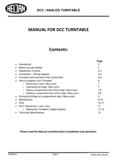
DCC / ANALOG TURNTABLE<br />
MANUAL FOR DCC TURNTABLE<br />
Contents:<br />
Page:<br />
Introduction 2<br />
Before you get started 2<br />
Adjustment of tracks 2-3<br />
Connection – Wiring diagram 3-4<br />
Functions and overview of the Control Box 4-6<br />
How to program your Turntable 6<br />
o Performing a reset / Menu point 7<br />
o Calibrating the bridge / Menu point 7<br />
o Setting a programmed stop of the bridge / Menu point 7-8<br />
o Deleting a programmed stop of the bridge / Menu point 8-9<br />
Driving the bridge to a programmed stop / Menu point 9<br />
Maintenance 9-10<br />
FAQ 10-11<br />
DCC Uhlenbrock / Lenz / Esu 11<br />
o Setting the Turntable´s digital address 11-12<br />
Technical Specifications 12<br />
Please read the Manual carefully before installation and operation.<br />
84089121 Page 1<br />
WWW.HELJAN.DK<br />
WWW.HELJAN.DK
a)<br />
b)<br />
1. Introduction<br />
Dear Customer!<br />
DCC / ANALOG TURNTABLE<br />
Thank you for purchasing the “HELJAN DCC / Analog Turntable”.<br />
Your new HELJAN Turntable has many features; therefore it is important to carefully read this guide before<br />
installing it on your layout. The turntable is like a small <strong>com</strong>puter, working on very small voltage / impulses,<br />
therefore it is important always to keep the moving <strong>com</strong>ponents (gears, optical eye etc.) very clean.<br />
HELJAN has produced a turntable that meets all the requirements needed for a modern DCC layout.<br />
If installed and used correctly, this product will give years of service!<br />
2. Before you get started<br />
Your turntable should be powered from its own transformer (not included).<br />
Check the output of the transformer is correct for this use before making any electrical connections.<br />
The ideal voltage to operate the turntable is 15v AC, 500 mA.<br />
The opening in the wall of the pit houses the optical sensor and is used as the ``zero point´´.<br />
For the indexing to work properly, this area and the small gear teeth and ring rail moulded in the bottom of the<br />
pit, must be clean and open at all times. If you wish to paint or weather the pit further, mask off these areas<br />
before starting. Please note that it´s not possible to make a position directly at the ``zero point´´.<br />
Before installing the pit, cover the centre pivot hole with tape to keep out dust and debris.<br />
Your new turntable must be installed on a flat, stable and level surface. Determine the location for your pit and<br />
use the enclosed template to cut the mounting hole in your baseboard. Allow at least 2¼´´ (5.7 cm) of clearance<br />
below the pit. The zero reader is mounted directly below a mounting boss; be sure to provide clearance in your<br />
baseboard for the reader too.<br />
Pre-drill the positions for the mountings as shown on the template with an 8 mm bit. Secure the pit in place using<br />
eight screws and washers (not included) - do not over tighten as this could cause the pit to warp.<br />
If you are using foam / polystyrene for the surface of your layout, open the areas for the mounting bosses slightly<br />
and push the pit into place.<br />
Make sure the pit is level, secure and properly supported before proceeding.<br />
When you have removed the bridge from the pit, it´s important that the power is switched off.<br />
3. Adjustment of tracks<br />
With the pit in place, you can install the approach/exit tracks. The indexing can be programmed for up to 48<br />
different stopping positions, so you can add tracks almost anywhere around the pit – but remember, don’t install<br />
tracks in the ``NO TRACK´´ areas.<br />
84089121 Page 2<br />
WWW.HELJAN.DK
a)<br />
DCC / ANALOG TURNTABLE<br />
The bridge is equipped with a Code 83 rail-profile; if you are using another profile for your track, use of transition<br />
tracks may be necessary. The top of your rails and the bridge rails must be level.<br />
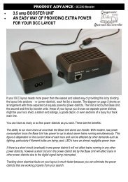
For a smooth transition between the bridge and service tracks, you need to modify your rails by filing the inside<br />
at a slight angle for about 3/16´´ (4 mm) (see Fig. 1).<br />
For the rails to sit correctly on the lip of the pit, you must<br />
remove a few sleepers from the end of the track.<br />
Important note: Leave a gap of about 1/16´´(1.5 mm)<br />
between the end of each service track and the bridge.<br />
All service tracks must align with the bridge rails in a<br />
straight line. The bridge can be used as a guide.<br />
Wire the service tracks (parts not included) for power as<br />
desired.<br />
You must fix the position of your service tracks, before you program the positions.<br />
4. Connection – Wiring-diagram<br />
Wire diagram for DCC:<br />
84089121 Page 3<br />
Remove with a file<br />
Fig.1<br />
Please note that your DCC Turntable automatically reverses the track polarity in the “ No Track” area. It is<br />
therefore important that you are aware of the polarity over and under the “No Track” area.<br />
Wire diagram for Analog:<br />
WWW.HELJAN.DK
)<br />
c)<br />
a)<br />
DCC / ANALOG TURNTABLE<br />
All red wires should be connected.<br />
All blue wires should be connected.<br />
If a short circuit occurs when the loco is running onto the bridge, the wires in screw terminal 1 and 2 should be<br />
reversed.<br />
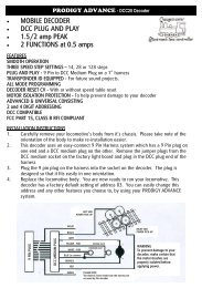
Finish by vacuuming and cleaning your Turntable.<br />
Clean the contacts in the pit and on under the bridge. See Fig. 4<br />
Contacts under bridge Contacts in Pit<br />
5. Functions and overview of the Control Box<br />
84089121 Page 4<br />
Contact under bridge: Clean in Propyl Alcohol or similar<br />
and finish by wiping with a dry cloth.<br />
Contacts in Pit: Clean in Propyl Alcohol or similar. Use a<br />
cotton bud and be careful, not to bend the contacts,<br />
because this may affect the contact to the bridge.<br />
It is important that the power is switched off when you<br />
clean the contacts<br />
Operational overview<br />
The electronic control integrated into the Control Box for the turntable has the following characteristics:<br />
Analogue and digital operation<br />
The turntable can be used on analogue model railway layouts as well as digital model railway layouts run in DCC<br />
format. In analogue operation the turntable is run via the control box. In digital operation it is possible to remotecontrol<br />
the turntable from a digital control unit via the Control Box.<br />
The electronic control automatically recognizes the operational mode (analogue or digital) and the digital format<br />
DCC that is run.<br />
Settings<br />
The electronic control allows you to define up to 48 individual stops of the bridge.<br />
Please note: Stops can be added or deleted separately at any time. Also please note, that when a<br />
position/stop is set, a 180 degree position/stop, from current position, is automatically set.<br />
Running<br />
The motor running the bridge is driven with a starting and braking delay that replicates the<br />
operational characteristics of the prototype.<br />
WWW.HELJAN.DK
Connecting power supply and turntable<br />
b)<br />
c)<br />
1<br />
2<br />
4<br />
5<br />
Display and function keys of the Control Box<br />
2<br />
A<br />
1<br />
4<br />
5<br />
1 2 3 4<br />
Escape<br />
Go/Set<br />
B<br />
Escape<br />
Go/Set<br />
DCC / ANALOG TURNTABLE<br />
Bridge speed HI<br />
Bridge speed LO<br />
84089121 Page 5<br />
6<br />
7<br />
Bridge speed HI<br />
Bridge speed LO<br />
3<br />
Turntable<br />
Connect the turntable to the Control Box the<br />
cable which is supplied.<br />
Power supply<br />
Connect the control box either to the booster of your digital<br />
layout or to the AC power supply of your analogue layout<br />
(not exceeding 18vAC). Do not mix up the connections!<br />
See Fig. 2+3 on page 4<br />
Display<br />
The digital display has 4 digits. During operation and while making settings, all relevant information is shown<br />
here. A flashing display indicates that you can make settings or that the bridge is moving.<br />
Function key ``UP´´ (CW)* and 3 Funktion key ``DOWN´´ (CCW)*<br />
The function keys ``UP´´ and ``DOWN´´ are used for:<br />
- to scroll in the menu or<br />
- to alter values to be set<br />
Where a wide choice of values is available the keys have a repeating function:<br />
When pushing them for a longer time the values are not altered one by one but very quickly.<br />
A<br />
B<br />
Function key ``ESCAPE´´<br />
The function key ``ESCAPE´´ is used to quit a menu point. If settings have been made, they are not saved.<br />
Function key ``GO/SET´´<br />
The function key ``GO/SET´´ is used to<br />
- to enter into a menu point or<br />
- to save settings<br />
- to initiate bridge movement<br />
- If you are positioned at a stop and you press ``GO/SET´´ again, the bridge turns 180 degrees from your current<br />
position.<br />
WWW.HELJAN.DK
d)<br />
e)<br />
DCC / ANALOG TURNTABLE<br />
Menu of the Control Box<br />
The control <strong>com</strong>mands for the Control Box are organized in a menu:<br />
Menu point Remark<br />
Tr<br />
Driving the bridge to set a stop<br />
The displays shows after ``Tr `` the digit number (1 to 48)<br />
of the stop where the bridge currently is<br />
Cal<br />
Prog<br />
Del<br />
Adr<br />
bl<br />
Res<br />
Navigating through the menu<br />
1. Choosing a menu point:<br />
Press the function keys ``UP´´ or ``DOWN´´ for scrolling from one menu entry to another.<br />
2. Entering into a menu entry:<br />
Press the function key ``GO/SET´´. The name of the menu entry, shown in the display, starts to flash. In<br />
case of error, press the function key ``ESCAPE´´.<br />
3. Choosing a value:<br />
Press the function keys ``UP´´ or ``DOWN´´ to alter the value in the display. The keys have a repeating<br />
function:<br />
When pushing them for a longer time the values are not altered one by one but very quickly.<br />
4. Saving a chosen value:<br />
Press the function key ``GO/SET´´ or turning the bridge 180 degrees.<br />
5. Leaving a menu entry without saving the settings:<br />
Press the function key ``ESCAPE´´.<br />
6. How to program your Turntable<br />
Put the bridge onto the turntable pit, plug the grey cable into the control box and switch<br />
on the power supply. The display shows in a moving screen Heljan.<br />
Note: The circular contact ring and wipers must be ultra-clean with digital operation.<br />
Clean both parts in Propyl Alcohol or a similar cleaner any time the bridge is<br />
removed and installed.<br />
Before you start using your Turntable, please perform a Reset as follows:<br />
84089121 Page 6<br />
Calibrating the ``0´´-position of the bridge<br />
This should be done always<br />
- after putting the bridge into the turntable pit<br />
- after altering the bridge position by hand<br />
- after the power supply has been interrupted while the<br />
bridge was moving or a programme has just been set.<br />
- after programming is done<br />
Setting a stop for the bridge and numerating the<br />
stopping position<br />
Deleting a stop of the bridge<br />
Setting the turntable’s digital address<br />
Performing a reset / restoring the factory settings<br />
WWW.HELJAN.DK
)<br />
a)<br />
c)<br />
Performing a reset / Menu point<br />
DCC / ANALOG TURNTABLE<br />
By performing a reset you will restore the factory settings.<br />
Please note: All settings you have made will be deleted!<br />
In order to perform a reset follow these steps:<br />
1. Scroll to the menu point<br />
2. Press the function key ``GO/SET´´. ``Res´´ in the display starts to flash. If you want to<br />
cancel, press ``ESCAPE´´.<br />
3. Press the function key ``GO/SET´´ again. The display shows a ``y´´ to the left and<br />
a flashing ``n´´ to the right.<br />
4. Confirm your choice by pressing the function key ``UP´´ for ``yes, performing a reset´´ or<br />
``DOWN´´ for ``no / escape´´.<br />
5. After having pressed the function key ``UP´´ for ``performing a reset´´ the display shows in a<br />
moving screen ``heljan´´, and return to the Tr mode.<br />
6. Finish by calibrating. See Section 6B.<br />
Calibrating the bridge / menu point<br />
The bridge will automatically calibrate itself, when travelling past the zero position during<br />
normal operation. The zero position is where the sensor is located in the side of the pit.<br />
However, there are times when you have to calibrate the bridge<br />
(See section 5D `Menu of the control box´ for more information).<br />
To calibrate, follow these instructions:<br />
1. Scroll to the menu point .<br />
2. Press the function key ``GO/SET´´. ``Cal´´ in the display starts to flash.<br />
In case you want to cancel, press ``ESCAPE´´.<br />
3. Press the function key ``GO/SET´´ again ``Cal´´ in the display flashes half as quick as before.<br />
The bridge will start to turn first slow, then fast until it reaches ``0´´-position and then stop at the pre-installed<br />
position 1.<br />
Please note, If the bridge does not stop at position ``1´´ after calibration a counting error has<br />
occurred and the bridge needs to be calibrated again.<br />
Setting a programmed stop of the bridge / Menu point<br />
1. Scroll to the menu point ``Prog´´.<br />
2. Press the function key ``GO/SET´´. ``Prog´´ in the display starts to flash. In case you want to<br />
cancel, press ``ESCAPE´´.<br />
84089121 Page 7<br />
WWW.HELJAN.DK
d)<br />
DCC / ANALOG TURNTABLE<br />
3. Start the bridge moving by pressing the function keys ``UP´´ or ``DOWN´´ for a short time.<br />
To stop the bridge at the selected position press the function keys ``UP´´ or ``DOWN´´ again.<br />
The fine tuning of the position can be done with the ``UP´´ and ``DOWN´´.<br />
Attention: Always finish positioning the bridge in the same direction you started programming in.<br />
4. Save the chosen position by pressing the function key ``GO/SET´´ again.<br />
5. ``P´´ in the display is shown and the highest available number for a position is suggested<br />
in the display. If necessary choose a lower number by pressing the function key ``UP´´ or ``DOWN´´.<br />
Selecting a lower number is equal to inserting a position between already programmed positions. This implies<br />
That all programmed positions above the point of insertion is incremented by one position number.<br />
6. Save the chosen number by pressing the function key ``GO/SET´´ again.<br />
7. Finish by calibrating the bridge. See section 6B.<br />
Special feature: Please note, that when a position/stop is set, a 180 degree position/stop, from current<br />
position, is automatically set.<br />
NOTE: It is not possible to make a position directly at the ``zero point´´.<br />
Note: If you accidentally push the ``GO/SET´´ when you wish to stop at a desired position,<br />
the display flashes with a suggested position number. Press ``ESCAPE´´. The bridge stops and<br />
the display shows ``Prog´´ .Push ``GO/SET´´ and then the ``UP´´ or ``DOWN´´ function keys<br />
twice and find the correct position. Always stop with ``UP´´ function key.<br />
Please note: The program does not allow to leave out a number for a stop. Example:<br />
You have already four stops (which have been assigned the numbers 1 to 4)<br />
You want to set a new stop (the fifth)<br />
Either no. 5 (which is suggested automatically)<br />
Or a lower no. (1, 2, 3, 4)<br />
In case you choose a lower number (e.g. no. 2) the program automatically renumbers the stops<br />
As shown below:<br />
Stop numbers before setting the fifth stop<br />
Stop numbers when setting the suggested<br />
number for the new fifth stop<br />
Stop numbers when choosing the no. 2 for<br />
the new (fifth) stop<br />
NOTE: Positions 1 and 2 (are related to the zero point) are not programmable positions; start with track 3 when<br />
you program tracks. When you have made minimum 2 new stops, you are able to remove the<br />
pre-installed position 2. Also please note that it´s not possible to make a position directly at the ``zero point´´.<br />
Deleting a programmed stop of the bridge / Menu point<br />
In order to delete a position of the bridge follow these steps:<br />
84089121 Page 8<br />
1<br />
1<br />
1<br />
Old stops<br />
2<br />
2<br />
3<br />
3<br />
4<br />
4<br />
New stop<br />
---<br />
4<br />
3 5 2<br />
5<br />
WWW.HELJAN.DK
1. Scroll to the menu point ``del´´<br />
2. Press the function key ``GO/SET´´<br />
DCC / ANALOG TURNTABLE<br />
3. Press the function key ``GO/SET´´ again. The display shows a ``d´´<br />
and the number of your current stop. If you want to delete another stop than the chosen one, simply choose<br />
another by pressing the “UP” or “DOWN” buttons. Please note that deleting a position causes all positions<br />
above the deletion point to be decremented by one position number.<br />
4. Delete the chosen stop by pressing the function key ``GO/SET´´ again.<br />
All positions with a number higher than the deleted one are renumbered automatically.<br />
Please note: After <strong>com</strong>pletion of deleting desired positions, the display always returns to show Tr 1.<br />
7. Driving the bridge to a programmed stop / Menu point<br />
In order to change the bridge’s position, follow these steps:<br />
1. Scroll to the menu point ``tr´´. The digit no. shows the current position of the bridge.<br />
2. Press the function key ``GO/SET´´. ``tr´´ in the display starts to flash.<br />
In case you want to cancel, press ``ESCAPE´´.<br />
Remark: In order to avoid involuntary changes of the bridge’s position by pressing the function<br />
keys ``UP´´ or ``DOWN´´ by accident you need to press the function key ``GO/SET´´ first before<br />
choosing a new position for the bridge. When just pressing the function keys ``UP´´ or ``DOWN´´<br />
you will scroll from one menu point to another.<br />
3. Press the function keys ``UP´´ or ``DOWN´´ to choose the number of the track position to go to. Only the<br />
numbers of stops that have been programmed are shown.<br />
4. Press the function key ``GO/SET´´ again. ``tr´´ in the display flashes half as fast as before<br />
and the bridge will move to the next track position.<br />
Please note: If the bridge is already at the selected position number and you’ve gone all the way to step 4, then<br />
The bridge will do a 180 degree turn from its current position.<br />
8. Maintenance<br />
As operation can be affected by dust, it is re<strong>com</strong>mended to cover your Turntable between operating sessions.<br />
Zero Point: Make sure this area and the pit edge is always clean and free of dust.<br />
84089121 Page 9<br />
WWW.HELJAN.DK
DCC / ANALOG TURNTABLE<br />
Use Propyl Alcohol or a similar cleaner to clean the contacts on the bottom of the bridge and in the pit, should<br />
they get dirty.<br />
Important note: Any time the bridge is removed from the pit, you must calibrate (see 6B) before resuming<br />
operation in order for the bridge to find the positions correctly.<br />
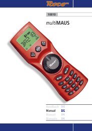
Lubrication: In normal use, the drive mechanism should only require servicing about once a year. Use plastic<br />
<strong>com</strong>patible lubricants made especially for hobby products – NEVER use household oils or lubricants!<br />
Remove the screws from the cover. Apply a drop of light oil to both motor bearings and the drive gear train. (See<br />
Fig. 5)<br />
Reverse these steps to reassemble – make sure the motor leads are positioned as shown.<br />
FIG. 5<br />
9. FAQ<br />
Grease here<br />
Keep gear<br />
clean<br />
Light oil<br />
If the bridge doesn’t stop at programmed position and won’t move again or the control box<br />
reads ``C´´:<br />
Proper contact is not being made between the wipers and the bridge centre post. See 4C for cleaning contacts<br />
and finish by Calibrating, see 6B.<br />
If the bridge, in “Prog. Mode”, is running much slower CCW than CW:<br />
It is re<strong>com</strong>mended to let it run at least 1 turn CCW in “Prog. Mode”. Then the mechanical parts will be more<br />
flexible.<br />
When driving the bridge to another stop the bridge does not stop exactly at the set position:<br />
1. Possible cause: The bridge has been removed from the pit or its position has been altered by hand or the<br />
power supply has been interrupted while the bridge was moving or a position has just been programmed.<br />
Calibrate the bridge again (see section 6B).<br />
2. Possible cause: When setting a new stop the positioning of the bridge was not finished in the same direction<br />
it was started. Due to technical reasons this does not allow an exact re-finding of the position. Delete the position<br />
and set it again (see chapter 6D).<br />
The display in the Control box reads Err1:<br />
There is no contact to the bridge. Please try to clean the contacts as described in the Installation Instructions,<br />
section: Troubleshooting. Also please check the wire-connection.<br />
84089121 Page 10<br />
WWW.HELJAN.DK
a)<br />
b)<br />
c)<br />
DCC / ANALOG TURNTABLE<br />
In DCC Mode: If the DCC Command station does not respond. Make sure the Control Box is set to Tr<br />
mode.<br />
10. DCC Uhlenbrock / Lenz / ESU<br />
The Turntable is <strong>com</strong>patible with the official NMRA Digital Command and Control (DCC) standard.<br />
The turntable is connected to your layout by connecting the control box terminals directly to<br />
the Booster output of your main control station. The connection details are depicted in figure 3, page 4.<br />
In case of a short-circuit, when driving a loco onto the bridge, the wires connected to the turntable control box (1<br />
and 2) need to be swapped.<br />
The control box <strong>com</strong>es with a default accessory value of 057 (see section 10b for changing the default set digital<br />
value) and it occupies the next 25 sub-addresses. Please mind that no other accessory decoder should be<br />
located in the range covered by the control box. Please note that the accessory decoder address has no<br />
influence on the loco address.<br />
Please note: The set value is not identical with the digital address (as this is an accessory decoder´s address).<br />
From the factory there are two preprogrammed positions on the turntable (1 and 2):<br />
This means that track 1 will be assigned address 225 Red/curve, track 2 will be assigned address 225 Green/<br />
straight.<br />
Track 3 will be assigned address 226 Red/curve, track 4 will be assigned address 226 Green/ straight.<br />
Now you'll be able to control the turntable like any other accessory decoder on your layout.. While controlling the<br />
turntable from your digital control unit, the control box will depict which track position the turntable is turning<br />
toward, (this requires that the control box menu is set in “tr” mode.<br />
Furthermore can <strong>com</strong>puter software you may wish to use to control your main layout, also control the turntable.<br />
Setting the turntable’s digital address / Menu point<br />
In order to set the turntable’s digital address, follow these steps:<br />
1. Scroll to the menu point “Adr”.<br />
2. Press the function key ``GO/SET´´. “Adr” in the display starts to flash. If you want to cancel, press ``ESCAPE´´.<br />
3. Press the function key ``GO/SET´´ again. The display shows a flashing “A” and the 3-digit number of the current<br />
address.<br />
4. Choose a new value by pressing the function keys ``UP´´ or ``DOWN´´.<br />
Advice: The keys have a repeating function: When pushing them for a longer time the values are not altered one<br />
by one but very quickly.<br />
5. Save the chosen value by pressing the function key ``GO/SET´´ again.<br />
Please note: The set value is not identical with the digital address (as this is an accessory decoder’s address).<br />
Further information regarding changing the control box's accessory address:<br />
First of all you need to find the address to assign to the included control box. This is ac<strong>com</strong>plished by finding the<br />
desired accessory sub-address and performing the following calculation:<br />
84089121 Page 11<br />
WWW.HELJAN.DK
d)<br />
DCC / ANALOG TURNTABLE<br />
57x4=228. Accessory address = ( (DCC Address - 1) * 4 ) + 1<br />
for example if DCC Address = 57 then<br />
Accessory Address = ( (57-1) * 4 ) + 1 = 225.<br />
Please note that the bridge already has the digital address set to 57, so no calculation is need, unless you wish<br />
to change the address.<br />
Please note: The Control box must be in the “Track mode” (Tr must be displayed on the Control Box) in<br />
order to be able to drive the bridge from track to track via the digital <strong>com</strong>mand station (DCC).<br />
Please note: The Control box supports both state-full and state-less, also referred to a permanent and<br />
momentary – accessory decoders.<br />
The lowest accessory address selectable on the control box is 1, this yields accessory sub-<br />
address 5 for track position 1 and 1017 for track 48.<br />
The highest accessory address selectable on the included control box is 248, this yields accessory sub-address<br />
993 for track position 1 and 1017 for track 48.<br />
Accessory<br />
decoder’s<br />
address<br />
225<br />
225<br />
226<br />
227<br />
...<br />
249<br />
On a DCC System that has multiple options other than DCC (like Intellibox from Uhlenbrock), the accessory<br />
decoder settings should be set for DCC.<br />
If the booster shuts down (eg. short circuit on the track), while the Turntable bridge is running, you may need to<br />
calibrate the Turntable (see section 6b, page 8) to restore accuracy.<br />
11. Technical specifications<br />
Points to ``branding´´ Points to ``straight on´´<br />
First switching ``straight on´´ and afterwards ``branding´´ will reset all<br />
settings automatically to the state of delivery<br />
Stop no. 1 Stop no. 2<br />
Stop no. 3 Stop no. 4<br />
Stop no. 5 Stop no. 6<br />
... ...<br />
Stop no. 47 Stop no. 48<br />
Data formats: DCC (NMRA standard)<br />
Power supply: 15-18 Volt AC<br />
Power consumption: approx. 110 mA<br />
Maximum amount of accessory decoder’s addresses: 1020<br />
Protection: IP 00<br />
Ambient temperature while working: 0 to +60 Degrees Celcius<br />
Ambient temperature while not operating: -10 to +80 Degrees Celcius<br />
Maximum Humidity: max. 85%<br />
The Turntables consumption is approx. 150 mA when the bridge turns and approx. 50 mA in standby.<br />
84089121 Page 12<br />
WWW.HELJAN.DK