Rail-Built Buffer Stop - Gaugemaster.com
Rail-Built Buffer Stop - Gaugemaster.com
Rail-Built Buffer Stop - Gaugemaster.com

You also want an ePaper? Increase the reach of your titles
YUMPU automatically turns print PDFs into web optimized ePapers that Google loves.
1<br />
2<br />
3<br />
Images & content of this manual are the intellectual property of DCCconcepts Pty Ltd<br />
Page 2/4<br />
<strong>Rail</strong>-<strong>Built</strong> <strong>Buffer</strong> <strong>Stop</strong><br />
A Step by step installation and wiring guide<br />
I can be powered<br />
with AC, DC<br />
or DCC<br />
(6~15v)<br />
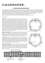
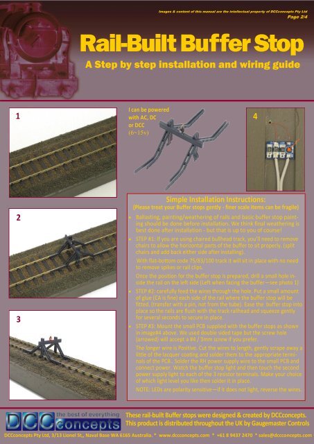
Simple Installation Instructions:<br />
(Please treat your <strong>Buffer</strong> stops gently - finer scale items can be fragile)<br />
Ballasting, painting/weathering of rails and basic buffer stop painting<br />
should be done before installation. We think final weathering is<br />
best done after installation - but that is up to you of course!<br />
STEP #1: If you are using chaired bullhead track, you’ll need to remove<br />
chairs to allow the horizontal parts of the buffer to sit properly. (split<br />
chairs and add back either side after installing).<br />
With flat-bottom code 75/83/100 track it will sit in place with no need<br />
to remove spikes or rail clips.<br />
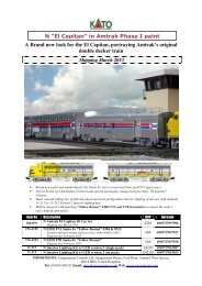
Once the position for the buffer stop is prepared, drill a small hole inside<br />
the rail on the left side (Left when facing the buffer—see photo 1)<br />
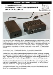
STEP #2: carefully feed the wires through the hole. Put a small amount<br />
of glue (CA is fine) each side of the rail where the buffer stop will be<br />
fitted. (transfer with a pin, not from the tube). Ease the buffer stop into<br />
place so the rails are flush with the track railhead and squeeze gently<br />
for several seconds to secure in place.<br />
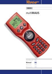
STEP #3: Mount the small PCB supplied with the buffer stops as shown<br />
in image#4 above. We used double sided tape but the screw hole<br />
(arrowed) will accept a #4 / 3mm screw if you prefer.<br />
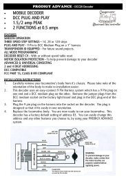
The longer wire is Positive. Cut the wires to length, gently scrape away a<br />
little of the lacquer coating and solder them to the appropriate terminals<br />
of the PCB.. Solder the RH power supply wire to the small PCB and<br />
connect power. Watch the buffer stop light and then touch the second<br />
power supply light to each of the 3 resistor terminals. Make your choice<br />
of which light level you like then solder it in place.<br />
NOTE: LEDs are polarity sensitive—if it does not light, reverse the wires.<br />
These rail-built <strong>Buffer</strong> stops were designed & created by DCCconcepts.<br />
This product is distributed throughout the UK by <strong>Gaugemaster</strong> Controls<br />
DCCconcepts Pty Ltd, 3/13 Lionel St,, Naval Base WA 6165 Australia. * www.dccconcepts.<strong>com</strong> * +61 8 9437 2470 * sales@dccconcepts.<strong>com</strong><br />
4