M50 Owner's Manual - Korg
M50 Owner's Manual - Korg
M50 Owner's Manual - Korg

You also want an ePaper? Increase the reach of your titles
YUMPU automatically turns print PDFs into web optimized ePapers that Google loves.
38<br />
Playing and editing Programs<br />
JS+Y Int specifies the amount of vibrato that the LFO<br />
will produce when the joystick is pushed away from<br />
you.<br />
Intensity (AMS Intensity) specifies the depth of<br />
vibrato that will be applied by the LFO when<br />
modulated by the selected AMS (Alternate Modulation<br />
Source). For example, if the panel switch assignment<br />
for SW1 is set to SW1 Mod. (CC#80) (Prog 1–7a), and<br />
you set LFO1 AMS to SW1: CC#80 and specify an<br />
appropriate value for Intensity, vibrato will be applied<br />
when you turn SW1 on or when MIDI control change<br />
#80 is received.<br />
Pitch EG<br />
When the Intensity value is set to +12.00, the pitch EG<br />
specified in the Pitch EG page will produce a<br />
maximum of ±1 octave of pitch change.<br />
To realistically simulate the slight change in pitch that<br />
occurs when a string is plucked or at the attack of a<br />
brass or vocal sound, you can use the EG to create a<br />
subtle change in pitch at the attack.<br />
Portamento<br />
Portamento makes the pitch change smoothly when<br />
you play the next note before releasing the previous<br />
note.<br />
The Time parameter controls how long it take the pitch<br />
to change. As this value is increased, the pitch will<br />
change over a longer time. With a value of 000, there<br />
will be no portamento.<br />
You can turn Portamento on and off via SW1 or SW2,<br />
by assigning them to Porta.SW CC#65.<br />
Using Filters<br />
The filters allow you to diminish or emphasize<br />
specified frequency areas of the sound.<br />
The tone of the sound will depend significantly on<br />
the filter settings.<br />
The basic filter settings, including the routing, type,<br />
cutoff frequency, and resonance, are set on the P3–1:<br />
Filter1 or P3–2: Filter2 page.<br />
Filter Routing<br />
Each oscillator has two filters, Filter A and Filter B. The<br />
Filter Routing parameter controls whether one or both<br />
of the filters are used, and if both are used, it controls<br />
how they are connected to each other.<br />
The Single routing uses only Filter A as a single 2-pole,<br />
12dB/octave filter (6dB for Band Pass and Band<br />
Reject).<br />
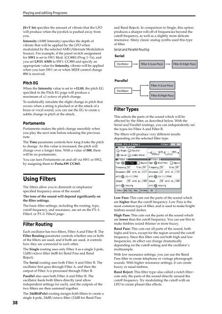
The Serial routing uses both Filter A and Filter B. The<br />
oscillator first goes through Filter A, and then the<br />
output of Filter A is processed through Filter B.<br />
Parallel also uses both Filter A and Filter B. The<br />
oscillator feeds both filters directly (and allow<br />
independent settings for each), and the outputs of the<br />
two filters are then summed together.<br />
The 24dB(4Pole) routing merges both filters to create a<br />
single 4-pole, 24dB/octave filter (12dB for Band Pass<br />
and Band Reject). In comparison to Single, this option<br />
produces a sharper roll-off of frequencies beyond the<br />
cutoff frequency, as well as a slightly more delicate<br />
resonance. Many classic analog synths used this type<br />
of filter.<br />
Serial and Parallel Routing<br />
Oscillator<br />
Oscillator<br />
Filter Types<br />
Filter A (Low Pass)<br />
Filter A (Low Pass)<br />
Filter B (High Pass)<br />
Filter B (High Pass)<br />
This selects the parts of the sound which will be<br />
affected by the filter, as described below. With the<br />
Serial and Parallel routings, you can independently set<br />
the types for Filter A and Filter B.<br />
The filters will produce very different results<br />
depending on the selected filter type.<br />
Low Pass: This cuts out the parts of the sound which<br />
are higher than the cutoff frequency. Low Pass is the<br />
most common type of filter, and is used to make bright<br />
timbres sound darker.<br />
High Pass: This cuts out the parts of the sound which<br />
are lower than the cutoff frequency. You can use this to<br />
make timbres sound thinner or more buzzy.<br />
Band Pass: This cuts out all parts of the sound, both<br />
highs and lows, except for the region around the cutoff<br />
frequency. Since this filter cuts out both high and low<br />
frequencies, its effect can change dramatically<br />
depending on the cutoff setting and the oscillator’s<br />
multisample.<br />
With low resonance settings, you can use the Band<br />
Pass filter to create telephone or vintage phonograph<br />
sounds. With higher resonance settings, it can create<br />
buzzy or nasal timbres.<br />
Band Reject: This filter type–also called a notch filter–<br />
cuts only the parts of the sound directly around the<br />
cutoff frequency. Try modulating the cutoff with an<br />
LFO to create phaser-like effects.