DUPREX 5000 Series RF INSTALLATION GUIDE - Galaxy Control ...
DUPREX 5000 Series RF INSTALLATION GUIDE - Galaxy Control ...
DUPREX 5000 Series RF INSTALLATION GUIDE - Galaxy Control ...

You also want an ePaper? Increase the reach of your titles
YUMPU automatically turns print PDFs into web optimized ePapers that Google loves.
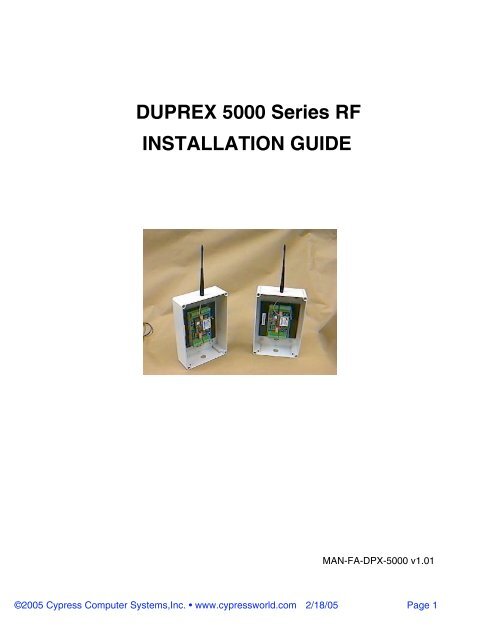
<strong>DUPREX</strong> <strong>5000</strong> <strong>Series</strong> <strong>RF</strong><br />
<strong>INSTALLATION</strong> <strong>GUIDE</strong><br />
MAN-FA-DPX-<strong>5000</strong> v1.01<br />
©2005 Cypress Computer Systems,Inc. • www.cypressworld.com 2/18/05 Page 1
Connector Terminal Identification- Quick Reference<br />
Panel /Port # 1 Signals<br />
Alarm Programming Resistor<br />
Aux #3 Programming Resistor<br />
Aux Digital I/O #1 Input<br />
Aux Digital I/O #2 Output<br />
Aux Digital I/O #3 Output<br />
Alarm Relay N.O.<br />
Alarm Relay Com<br />
Alarm Relay N.C.<br />
LED<br />
Data 1 /Data<br />
Data 0 /Clock<br />
+5 VDC<br />
Ground<br />
+8 - 24 VDC<br />
Reader # 1 Signals<br />
Alarm Digital Input<br />
Aux Digital I/O #3 Input<br />
Aux Digital I/O #1 Output<br />
Aux Digital I/O #2 Input<br />
N/C<br />
Strike Relay N.O<br />
Strike Relay Com<br />
Strike Relay N.C.<br />
LED<br />
Data 1 /Data<br />
Data 0 /Clock<br />
+5 VDC<br />
Ground<br />
+8 - 24 VDC<br />
Line -<br />
Line +<br />
Reader # 2 Signals<br />
Strike Relay N.C.<br />
Strike Relay Com<br />
Strike Relay N.O.<br />
N/C<br />
Aux Digital I/O #2 Input<br />
Aux Digital I/O #1 Output<br />
Aux Digital I/O #3 Input<br />
Alarm Digital Input<br />
©2005 Cypress Computer Systems,Inc. • www.cypressworld.com 2/18/05 Page 2<br />
C<br />
Duprex Central Unit<br />
Line -<br />
Line +<br />
+V<br />
Gnd<br />
+V<br />
Gnd<br />
R<br />
Duprex Remote Unit<br />
Panel/Port # 2 Signals<br />
+8 - 24 VDC<br />
Ground<br />
+5 VDC<br />
Data 0 /Clock<br />
Data 1 /Data<br />
LED<br />
Alarm Relay N.C<br />
Alarm Relay Com<br />
Alarm Relay N.O<br />
Aux Digital I/O #3 Output<br />
Aux Digital I/O #2 Output<br />
Aux Digital I/O #1 Input<br />
Aux #3 Programming Resistor<br />
Alarm Programming Resistor<br />
+8 - 24 VDC<br />
Ground<br />
+5 VDC<br />
Data 0 /Clock<br />
Data 1 /Data<br />
LED
DIP Switch Settings- Quick Reference<br />
1 2 3 4 5 6 7 8<br />
Service/Config Mode<br />
On<br />
Off<br />
1 2 3 4 5 6 7 8<br />
CENTRAL UNIT ONLY<br />
Dip switch #5 is ON<br />
Door Strike relay does NOT follow LED<br />
(Auxiliary setting)<br />
Address Setting Reader Format<br />
Channel Switch<br />
Address 2 3 4<br />
0<br />
1 x<br />
2 x<br />
3 x x<br />
4 x<br />
5 x x<br />
6 x x<br />
0 x x x<br />
x = ON<br />
Wiegand<br />
Wiegand / No Filter<br />
Strobed Rising Edge (MR-5)<br />
Strobed Rising Edge (Dorado 644)<br />
Strobed Rising (Mag-Tek)<br />
Strobed Falling Edge<br />
Reserved<br />
Reserved<br />
Switch<br />
6 7 8<br />
0<br />
1 x<br />
2 x<br />
3 x x<br />
4 x<br />
5 x x<br />
6 x x<br />
7 x x x<br />
All settings except Switch 5 are the same for Central and Remote units.<br />
©2005 Cypress Computer Systems,Inc. • www.cypressworld.com 2/18/05 Page 3
FCC Part 15 Notice of Compliance<br />
This device operates under Part 15 of the FCC rules. There are several requirements that<br />
must be met to maintain compliance.<br />
These devices can only be used with approved antennas.<br />
The antennas for these units MUST be mounted at a distance of 20 cm or greater from any<br />
nearby persons.<br />
This equipment has been tested and found to comply with the limits for a Class A digital device,<br />
pursuant to part 15 of the FCC Rules. These limits are designed to provide reasonable<br />
protection against harmful interference in a commercial installation. This equipment<br />
generates, uses, and can radiate radio frequency energy and, if not installed and used in<br />
accordance with the instructions, may cause harmful interference to radio communications.<br />
However, there is no guarantee that interference will not occur in a particular installation. If this<br />
equipment does cause harmful interference to radio or television reception, which can be<br />
determined by turning the equipment off and on, the user is encouraged to try to correct the<br />
interference by one or more of the following measures:<br />
- Reorient or relocate the receiving antenna<br />
- Increase the separation between the equipment and receiver.<br />
- Connect the equipment into an outlet on a circuit different from that to which the receiver is<br />
connected.<br />
- Consult the dealer or an experienced radio/TV technician for help.<br />
FCC Part 15 COMPLIANCE<br />
This device complies with part 15 of the FCC Rules.<br />
Operation is subject to the following two conditions:<br />
(1) This device may not cause harmful interference, and<br />
(2) this device must accept any interference received,<br />
including interference that may cause undesired operation.<br />
©2005 Cypress Computer Systems,Inc. • www.cypressworld.com 2/18/05 Page 4
The Cypress Duprex <strong>RF</strong> is the newest member of the Suprex family of products.<br />
The Duprex <strong>RF</strong> <strong>5000</strong> series supports a wide range of additional features from previous<br />
versions of the Suprex <strong>RF</strong> family.<br />
Additional features:<br />
--Field configurable channel selection<br />
--Diagnostic mode for setup and configuration<br />
--“Quiet” <strong>RF</strong> protocol to conserve bandwidth and power<br />
--Field configurable reader formats<br />
--Additional indicators for determining operational status of the unit<br />
Initial setup and configuration.<br />
The Duprex <strong>RF</strong> unit operates as a matched pair of units that share the same communication<br />
channel.<br />
Default settings from the factory are for Channel 0 unless specified otherwise by the customer<br />
If more than one pair are going to be used at the same site, then they should be set to different<br />
channels.<br />
There are four dip switches that are used for the <strong>RF</strong> portion of the Duprex (see quick reference<br />
diagram for DIP switch numbers).<br />
The first switch is the Setup/Config switch. This switch has multiple functions. With the switch in<br />
the OFF position, the unit operates in Normal mode. When the switch is in the ON position, the<br />
unit is in the Service / Configuration mode.<br />
When switching from Normal to Service / Configuration mode, the unit will reset and then load<br />
the current address setting on the DIP switch. While the switch remains in Service /<br />
Configuration, the unit will operate using a diagnostic protocol that will show communication<br />
activity between the Central and Remote units (The Yellow communication LED will flash<br />
rapidly).<br />
Once the address is loaded it will be saved in non volatile memory. When switching from<br />
Service / Configuration mode to Normal mode, the unit will reset and run with a “Quiet” <strong>RF</strong><br />
protocol. The address that is saved in memory will be used in operation.<br />
This Quiet protocol maintains communication between the Central and Remote units as<br />
necessary for I/O, Badge Activity, and Supervision without requiring continuous use of the <strong>RF</strong><br />
channel.<br />
Initial Setup;<br />
This manual will cover the basic installation procedure for a typical Duprex <strong>RF</strong> system.<br />
The first step will be to configure and test the units at a bench top location where both the<br />
Central and Remote units are close together. This will allow the setup and configuration<br />
process to occur with both sides of the operation in view.<br />
©2005 Cypress Computer Systems,Inc. • www.cypressworld.com 2/18/05 Page 5
Enclosure:<br />
Weatherproof Polystyrene<br />
10”H x 7” W x 3.5”<br />
Environmental Specifications:<br />
Enclosure NEMA 4X Rating<br />
Temperature Range -40 to 85 C<br />
Electrical Specifications:<br />
(Each Unit)<br />
Supply Voltage 8-24VDC<br />
Current 500mA<br />
Wall plug power supply included<br />
Radio Specifications:<br />
Frequency 900 MHz or 2.4 GHz unlicensed ISM band<br />
Type Frequency Hopping Spread Spectrum<br />
Transmit Power 100mW<br />
Receive Sensitivity -110 dBm<br />
Interference Rejection 70dB<br />
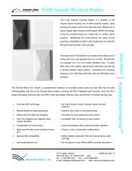
Antenna Options and typical range:<br />
1/2 wave whip- up to 2500 feet<br />
6 element Yagi - Up to 5 miles.<br />
Distances given are typical line of sight. Actual distance will vary<br />
depending upon terrain, <strong>RF</strong> environment, and height of antenna.<br />
Duprex Specifications:<br />
Specifications:<br />
Wiegand and Magstripe formats field selectable<br />
See Duprex manual for details.<br />
©2005 Cypress Computer Systems,Inc. • www.cypressworld.com 2/18/05 Page 6
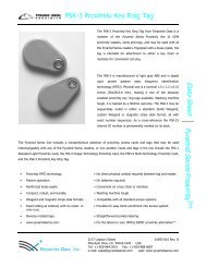
The Duprex <strong>RF</strong> package should contain:<br />
(1) Duprex <strong>RF</strong> Central unit (1) Duprex <strong>RF</strong> Remote unit<br />
(2) 1/2 wave whip antennas<br />
Unpack Units<br />
(2) Water resistant strain reliefs (8) Mounting screw seals<br />
Remove covers from units and check interior for any shipping damage. Remove any<br />
packing material if present.<br />
©2005 Cypress Computer Systems,Inc. • www.cypressworld.com 2/18/05 Page 7
BENCH TEST UNITS BEFORE <strong>INSTALLATION</strong><br />
Before installing the units in the field they should be assembled and tested at a convenient “Bench<br />
top” location. This will make it easier to verify / change settings and check operation when both<br />
units are visible at the same time.<br />
It is also a chance to become familiar with the system if this is the first time using the Duprex system.<br />
It is much more difficult to configure and test the units when they are several thousand feet apart.<br />
The units as shipped are configured to a default channel and are ready to plug in and operate.<br />
Both units need to have the antenna and a suitable power supply installed.<br />
Thread antenna lead<br />
through mounting hole.<br />
Use washer and nut to<br />
fasten into place<br />
1. Install antennas on both Central and Remote units.<br />
2. On both Central and Remote units<br />
connect power supply into PC board.<br />
Do not apply power at this time.<br />
Snap MMCX connector into<br />
place<br />
©2005 Cypress Computer Systems,Inc. • www.cypressworld.com 2/18/05 Page 8
Initial power up<br />
Plug in the Remote unit power supply.<br />
The Green power LED should illuminate<br />
The Amber com LED should be off<br />
The Diagnostic LED should illuminate a solid red color.<br />
Plug in the Central unit power supply.<br />
BENCH TEST UNITS<br />
The Green power LED should illuminate.<br />
The Amber com LED should flash and then go out.<br />
After a short delay, the Diagnostic LEDs on both the Central and Remote units<br />
should flash green on and off about once per second.<br />
Diagnostic LED (Red/Green/Yellow multi color)<br />
LED Indicator Location reference<br />
Communication<br />
Activity LED<br />
(Amber)<br />
Power LED (Green)<br />
©2005 Cypress Computer Systems,Inc. • www.cypressworld.com 2/18/05 Page 9
Setup / Config mode operation and channel selection<br />
How to set the channel:<br />
1. While Central and Remote units are still powered up on the bench, check dip<br />
switches 2,3,4 to make sure they are set to the required address. Switches 2,3,4 are all<br />
Off for the default channel 0 (zero).<br />
2. On the Remote unit, move DIP switch 1 to the Service / Config (ON) position.<br />
a. The unit will reset.<br />
b. The Amber com led will flash momentarily, then go dark.<br />
c. The diagnostic LED will flash Red twice.<br />
d. The diagnostic LED will flash green on and off about once per second.<br />
The Remote unit is now in Setup mode.<br />
3. On the Central unit, move DIP switch 1 to the Service / Config (ON) position.<br />
a. The unit will reset.<br />
BENCH TEST UNITS - Configuration Mode<br />
b. The Amber com led will flash rapidly on both the Central and Remote units.<br />
c. The diagnostic LED will flash green on and off about once per second.<br />
The addresses selected by the DIP switches will be loaded into memory. Make sure<br />
Central and Remote units are set to the SAME address!<br />
©2005 Cypress Computer Systems,Inc. • www.cypressworld.com 2/18/05 Page 10
The <strong>RF</strong> units are capable on operating on six different “Channels”. Units on different channels<br />
can operate in the same area with minimal interference to each other.<br />
Channel selection can be made in the field. If necessary, channel selection should be initially<br />
made while the units are together on a bench, so operation can be verified.<br />
Units are shipped from the factory with a default channel setting of 0 (zero). In some cases<br />
where multiple units are part of the same original order, different channel assignments may be<br />
made for different pairs of units. A sticker will be present on the unit to indicate the factory<br />
setting.<br />
If only one pair of units are being used, the default setting should be adequate and changing<br />
channels should not be necessary. Here follows a description of the Setup / Config mode.<br />
Setup / Config mode:<br />
BENCH TEST UNITS - Configuration Mode<br />
By setting DIP switch 1 to the ON position, the unit is placed in Setup / Config mode. This<br />
switch change can be made at any time. When the switch position is changed, the unit will<br />
reset and restart in the new mode. This is helpful for setup and diagnostic purposes.<br />
The Setup / Config mode has 2 primary functions:<br />
1. Places the units in rapid polling sequence to allow troubleshooting and setup of the<br />
communication link.<br />
2. Reads and saves the <strong>RF</strong> channel address from the DIP switch setting.<br />
The Duprex <strong>RF</strong> units use a quiet protocol when operating in normal mode. Communication<br />
between the Central and Remote unit only occurs when an event requires data transmission or<br />
contact needs to be made to maintain supervision. The <strong>RF</strong> channel remains quiet most of the<br />
time.<br />
During setup or troubleshooting it may be necessary to observe the communication link<br />
between the Central and Remote units. The rapid polling used in the Setup / Config mode can<br />
help indicate whether the units can “See” each other.<br />
©2005 Cypress Computer Systems,Inc. • www.cypressworld.com 2/18/05 Page 11
With the units a the rapid polling mode, the Amber com LED can be used to determine whether<br />
the units are in communication with each other.<br />
If communication is lost, the Alarm relay on the Central unit will activate, and the diagnostic LED will<br />
illuminate a solid Red color.<br />
Unplug the Remote unit.<br />
The Central unit diagnostic LED should display a solid Red color.<br />
Plug in the Remote unit.<br />
After the Remote unit restarts, the Central and Remote should resume communication and the<br />
Central unit diagnostic indicator should go back to flashing green.<br />
Now the units have their addresses set, operation has been confirmed, etc.<br />
Place the Central unit in Normal mode by moving DIP switch 1 to the OFF position.<br />
The Amber com LED should go out, the diagnostic LED will flash on and off about once per second.<br />
Place the Remote unit in Normal mode by moving DIP switch 1 to the OFF position.<br />
The setup config mode can be used once field installation is started to verify the communication path<br />
between units.<br />
Further Bench testing:<br />
If the reader and panel are conveniently located, it is advisable to connect the reader to the Remote<br />
unit, and the panel to the Central unit and test the units as a complete system. Use a test badge that<br />
has been programmed into the panel to test operation. See the DPX-7000 manual for electrical<br />
connections and further explanation of connecting readers and panels to the Duprex units.<br />
Remember to disconnect the provided “wall wart” power supply if using the panel power supply or<br />
other auxiliary supply. Only one power supply should be used for each unit.<br />
Connect the Central unit to the Access <strong>Control</strong> Panel (ACP)<br />
Connect the reader to the Remote unit.<br />
BENCH TEST UNITS - Configuration Mode<br />
Provide power to both units and verify communication.<br />
Use a test badge to verify operation of panel, reader, and connections.<br />
Doing the setup and initial testing with both the Central and Remote units when they are close<br />
together will save time if there are any problems that need to be corrected or installation issues that<br />
need to be clarified.<br />
Once the connection, setup, and configuration has been made with both units, field installation and<br />
final commissioning can be done.<br />
©2005 Cypress Computer Systems,Inc. • www.cypressworld.com 2/18/05 Page 12
Mounting the units.<br />
A site evaluation should have determined the optimal locations for the Central and<br />
Remote units, the type of antennas that would be needed, and the frequency band to<br />
be used. (See Cypress Application Note “Site Evaluation for Duprex <strong>RF</strong> products”).<br />
This section of the document covers units that utilize the enclosure mounted1/2 wave<br />
whip antenna. For other types of antennas there will be specific documentation to<br />
cover their different installation issues.<br />
We are now ready to physically mount the units and make the electrical connections to<br />
complete the installation.<br />
The units should be mounted so that the length dimension of the antennas are in the<br />
same plane. The orientation of the antenna will determine what is referred to as the<br />
polarization of the signal. Significant reduction in range can result if the units are not of<br />
the same polarity.<br />
See below.<br />
Both Central and Remote units are arranged so the antennas are parallel in direction. As shown<br />
in this illustration we would say they are both vertically polarized. Since the polarity is in the same<br />
direction, the signal strength would be maximized.<br />
In this instance one of the units is vertically polarized, and the other is horizontally polarized. The<br />
signal would be greatly reduced thereby reducing the maximum distance between units.<br />
The installer should make sure that both units are mounted so that the polarization will be the<br />
same for both units.<br />
In all cases the antennas MUST be mounted at a distance of 20 cm or greater from any nearby persons<br />
©2005 Cypress Computer Systems,Inc. • www.cypressworld.com 2/18/05 Page 13
Mounting the units - Antenna Orientation<br />
This orientation may reduce range. The metal pole is<br />
placed between antenna and other unit and the<br />
antenna is close to metal.<br />
The units should be mounted in such a way that there is as clear of a path as possible between the<br />
2 units. If mounting to a post or wall the unit should be placed where it has minimal interference<br />
with the antenna. Maximum signal and ranges are achieved when the antenna is clear of<br />
obstructions and is placed away from metal objects.<br />
Better, improved range. Antenna has line of sight to<br />
other unit. Proximity to metal pole may reduce range.<br />
Best, antenna has line of sight to other unit and is<br />
clear of adjacent metal objects.<br />
In all cases the antennas MUST be mounted at a distance of 20 cm or greater from any nearby persons<br />
©2005 Cypress Computer Systems,Inc. • www.cypressworld.com 2/18/05 Page 14
The other mounting method utilizes internal knockouts on the back of the unit. In some<br />
installations it<br />
may be easier to use these knockouts.<br />
Screw knockout<br />
Knockout end seal<br />
tabs<br />
Mounting the units-Hardware<br />
Inside Knockout Mounting Screws<br />
Knockout removed by<br />
pressing<br />
on it with screwdriver blade.<br />
Be<br />
careful not to damage interior<br />
components.<br />
Seal tab placed over<br />
knockout<br />
after screw has been<br />
fastened<br />
in place.<br />
Screw placed in knockout.<br />
©2005 Cypress Computer Systems,Inc. • www.cypressworld.com 2/18/05 Page 15
Mounting the units-Hardware<br />
There are two sets of mounting holes provided.<br />
The first set of mounting holes consists of the four corner channels that are also used to<br />
mount the cover plate screws.<br />
Four mounting screws can be threaded through the corner holes. This also is<br />
advantageous in that the screws do not breach any of the environmental seals.<br />
Mounting screws are not included due to the infinite variety of potential mounting surfaces.<br />
Select a type of mounting screw based on the type of material.<br />
Placement of screw in corner channel.<br />
Fasten screws in place with long<br />
handled<br />
screwdriver.<br />
Corner Channel Mounting Screws<br />
Screw placed into channel.<br />
©2005 Cypress Computer Systems,Inc. • www.cypressworld.com 2/18/05 Page 16
Plastic<br />
Nut<br />
With the units physically mounted. Pass the electrical cable through the watertight<br />
strain relief.<br />
It is recommended that all electrical connections enter through a single multi conductor<br />
cable. This will maintain the maximum resistance to the entry of debris and moisture.<br />
Individual cables and wires can be bundled and taped together and then passed<br />
through the connector if necessary.<br />
Connector<br />
Rubber Seal<br />
Electrical Connections<br />
Ring Washer Connector Hub<br />
With wires placed through the connector as shown, tighten Hub until rubber seal grips cable.<br />
Electrical connections can now be made. A quick reference diagram is included on the unit<br />
covers and in the beginning of this document. Details on the type and function of the individual<br />
connections are contained in the DPX-7000 manual. The DPX-7000 manual is included as part<br />
of the <strong>RF</strong> unit documentation package.<br />
All documents are available on the web at www.cypresscom.com<br />
Double check electrical connections and apply power to both units.<br />
The Green power LED should always be illuminated if power is applied. If this LED is not<br />
illuminated<br />
there is a power problem, or a problem with the unit.<br />
©2005 Cypress Computer Systems,Inc. • www.cypressworld.com 2/18/05 Page 17
Final Checkout<br />
The Green power LED should always be illuminated if power is applied. If this LED is not<br />
illuminated there is a power problem, or a problem with the unit.<br />
It is a good idea to switch both Central and Remote units to Service / Config mode to verify the field<br />
installation.<br />
Both units should be communicating. See bench test sequence for details for LED indicators<br />
when in Service / Config mode.<br />
Check operation of Badge reader, LED and other I/O that is used in the installation while in<br />
Service / Config mode.<br />
Once operation has been verified in Service / Config mode then the units can be placed in Normal<br />
Run mode. The Amber com LED will flash infrequently in Normal mode. It should flash each time<br />
a badge is swiped or any of the I/O changes status.<br />
The Central unit diagnostic LED will be Red when the units are not communicating. This may be<br />
happen when the Central unit powers up without the Remote unit having power. Once both units<br />
are powered up the diagnostic LEDs should both enter a flashing green on and off mode. This<br />
should occur within 30 seconds of both units having power applied in Normal mode.<br />
Check operation of Badge reader, LED and other I/O in Normal mode.<br />
Insert cover mounting screws and<br />
tighten.<br />
Installation is complete.<br />
©2005 Cypress Computer Systems,Inc. • www.cypressworld.com 2/18/05 Page 18