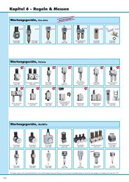
AerospaceIndustry - Frank Drucklufttechnik
AerospaceIndustry - Frank Drucklufttechnik
AerospaceIndustry - Frank Drucklufttechnik

Create successful ePaper yourself
Turn your PDF publications into a flip-book with our unique Google optimized e-Paper software.
I-5<br />
Cooper Power Tools Advanced Drilling Equipment<br />
Introduction<br />
Speed, Feed & Power<br />
Please use the chart below as a<br />
guide only. Many variables contribute<br />
to the optimum parameters for each<br />
application. These variables include:<br />
particular material characteristics,<br />
cutter design, cutter sharpness,<br />
airline pressure and flow capacity<br />
and cutter lubrication.<br />
All portable drilling tools have limited<br />
power and thrust. In most cases,<br />
holes over 1/2 inch diameter cannot<br />
be produced at machine tool rates.<br />
Feed rates and/or speeds are reduced.<br />
Consult Cooper Power Tools for<br />
advise on particular applications.<br />
For best results with your drilling system:<br />
1. Maintain lubricated air to the tool with pressure of 90 psig<br />
while the tool is running.<br />
2. Use high quality cutters.<br />
3. Replace cutters when point dulls – hole diameter generally increases,<br />
cycle times lengthen (except positive feed) and hole finish worsens.<br />
4. Whenever possible, provide lubricant mist to the drill point.<br />
5. Insure there is an adequate flow path for drill chips (swarf).<br />
6. Utilize fixtures that are secure and rigid.<br />
7. Assure that accessory items are sized correctly and working properly.<br />
8. Train operating personnel in the proper use of the tool.<br />
1/8 3/16 1/4<br />
Drill Diameter<br />
5/16 3/8 7/16 1/2<br />
Material Function .125 .188 .250 .313 .375 .437 .500<br />
Aluminum (300 SFM) Speed (RPM) 9000 6000 4600 3600 3000 2600 2300<br />
Feed Rate (IPR) .002 .003 .004 .004 .004 .004 .004<br />
Power (HP) .2 .3 .6 1.0 1.5 1.8 2.0<br />
Mild Steel (90 SFM) Speed (RPM) 2700 1800 1300 1100 900 750 650<br />
Feed Rate (IPR) .005 .005 .005 .006 .006 .006 .006<br />
Power (HP) .2 .3 .6 1.0 1.5 1.8 2.0<br />
High Strength Steel Speed (RPM) 900 600 450 375 300 250 220<br />
Stainless Steel Feed Rate (IPR) .001 .001 .001 .001 .001 .001 .001<br />
(30 SFM) Power (HP) .2 .3 .6 1.0 1.5 1.8 2.0<br />
Titanium/Inconel Speed (RPM) 600 400 300 250 200 175 150<br />
(20 SFM) Feed Rate (IPR) .002 .003 .003 .003 .004 .004 .005<br />
Power (HP) .2 .3 .6 1.0 1.5 1.8 2.0<br />
Composites Graphite, kevlar, fiberglass, and other composite materials vary widely. Fiber, resin, processing method and<br />
type of cutting tool all affect the optimum drilling speed and feedrate. Little power or thrust is normally<br />
required, but controlled feedrates at the proper speed is mandatory. Carbide or diamond cutting tools are<br />
required. Contact your material supplier or experiment with an NC Drilling Machine.<br />
Stacks of Various Materials Use the lowest speed and feedrate of the materials in the stack. Peck feed drilling is best.<br />
A. Peck Drilling permits higher drilling speeds B. Carbide cutting tools (when applicable) permits higher drilling speeds C. Oil hole cutting tools permit higher drilling speeds.<br />
Speed (RPM)<br />
Describes the number of revolutions<br />
of the spindle per unit of time.<br />
Example: Revolutions per minute=RPM<br />
Surface Speed (SFM)<br />
Describes the velocity (speed) of the<br />
outside of the drill bit.<br />
Example: 30 surface feet per minute (30 SFM)<br />
Feed Rate (IPR)<br />
Describes the distance the spindle travels<br />
during each revolution.<br />
Example: 0.002 inches per revolution = .002 IPR<br />
1 Revolution Time<br />
A<br />
Time<br />
1 Revolution<br />
Velocity at point A<br />
Distance<br />
Speed = Revolution ÷ Time Surface = Distance ÷ Time<br />
Feed Rate = Distance ÷ Revolution<br />
Speed (rotational)<br />
Cooper Power Tools Advanced Drilling Equipment<br />
Introduction<br />
Diameter<br />
Straightness<br />
Perpendicularity<br />
Barrelling<br />
Ovality<br />
Bellmouthing<br />
Benefits of Proper Hole Preparation<br />
Improved Hole Quality<br />
Diameter tolerance<br />
Countersink depth tolerance<br />
Hole finish<br />
Hole straightness<br />
Lack of burrs<br />
No delamination in composites<br />
No fiber fraying in composites<br />
No metallurgical change from excess heat<br />
Lowered Cost Per Hole<br />
Decrease the drilling time<br />
Reduce the number of operations for a finished hole<br />
Combine drilling and countersinking into one operation<br />
Self clamping attachments minimize hole to hole time<br />
Reduced Inventory & Capital Investment<br />
Portable equipment eliminates expensive, large<br />
stationary machines<br />
Simultaneous drilling and countersinking reduces total<br />
equipment requirements<br />
Self clamping significantly reduces fixturing costs<br />
Modular designs reduce the number of complete<br />
backup units<br />
Reduced Safety Hazards<br />
Less operator contact<br />
Drill bit control through nosepieces and fixtured<br />
bushings<br />
All reactions of the drilling process are absorbed by<br />
the fixture and drilling equipment<br />
I-6