Chapter 1 Introduction to AutoCAD - Goodheart-Willcox
Chapter 1 Introduction to AutoCAD - Goodheart-Willcox
Chapter 1 Introduction to AutoCAD - Goodheart-Willcox

Create successful ePaper yourself
Turn your PDF publications into a flip-book with our unique Google optimized e-Paper software.
This sample chapter is for review purposes only. Copyright © The <strong>Goodheart</strong>-<strong>Willcox</strong> Co., Inc. All rights reserved.<br />
wireframe model:<br />
The most basic 3D<br />
model—contains<br />
only information<br />
about object edges<br />
and the points<br />
where edges<br />
intersect, known as<br />
vertices; describes<br />
the appearance of<br />
the model as if it<br />
were constructed<br />
from wires.<br />
surface model:<br />
A 3D model that<br />
contains information<br />
about object edges,<br />
vertices, and the<br />
outer boundaries of<br />
the object, known<br />
as surfaces; surface<br />
models have zero<br />
thickness, lack<br />
mass, and may not<br />
enclose a volume.<br />
solid model: The<br />
most complex 3D<br />
model—contains<br />
information about<br />
object edges,<br />
vertices, surfaces,<br />
and mass; solid<br />
models enclose a<br />
volume.<br />
walkthrough: A<br />
computer simulation<br />
that replicates<br />
walking through or<br />
around a 3D model.<br />
flythrough: A<br />
computer simulation<br />
that replicates flying<br />
through or around a<br />
3D model.<br />
Figure 1-1.<br />
Au<strong>to</strong>CAD provides commands and options <strong>to</strong> accurately create 2D drawings for building<br />
design and construction, such as this architectural floor plan of a home.<br />
23'-0" 24'-0"<br />
12'-0"<br />
12'-0"<br />
12'-0"<br />
11'-0"<br />
9'-0"<br />
<strong>to</strong> manufacture or construct a product. 2D drawings are the conventional and often<br />
required method of communicating a project. Figure 1-1 shows an example of a 2D<br />
architectural floor plan created using Au<strong>to</strong>CAD. Use this textbook <strong>to</strong> learn how <strong>to</strong><br />
construct, design, dimension, and annotate 2D Au<strong>to</strong>CAD drawings.<br />
3D Models<br />
5<br />
28'-0"<br />
14'-0" 14'-0"<br />
C<br />
18'-0"<br />
C<br />
GARAGE<br />
27/0 X 23/0<br />
9'-0"<br />
C C<br />
LS<br />
LS<br />
5'-6"<br />
REFR<br />
HOOD W/ FAN<br />
KITCHEN<br />
9/0 X 11/5<br />
DINING<br />
9/5 X 8/9<br />
VAULT<br />
GFCI<br />
4<br />
CABLE<br />
3<br />
WP<br />
20'-0"<br />
9'-21 2 "<br />
64'-0"<br />
36'-0"<br />
6'-7"<br />
6'-9 1 4 " 5'-111 4 "<br />
5'-111 4 "<br />
13'-4 1 4 " 11'-101 2 " 10'-91 4 "<br />
2'-6" 2'-4"<br />
2'-2"<br />
B A<br />
2<br />
SD<br />
14'-5 1 4 "<br />
LIVING<br />
13/2 X 21/1<br />
VAULT<br />
3'-9"<br />
PORCH<br />
16/0 X 12/0<br />
A A<br />
2'-41 2 "<br />
PORCH<br />
7<br />
MASTER BEDROOM<br />
11/6 X 14/3<br />
BATH<br />
LFH<br />
10/0 X 7/2<br />
3'-3"<br />
36"<br />
SD<br />
FIBERGLASS<br />
SHOWER<br />
GFCI<br />
6<br />
LFH<br />
CLOSET LINEN<br />
BATH<br />
6<br />
6<br />
10/0 X 5/0<br />
1<br />
5'-3<br />
4'-0" 4'-0"<br />
6'-0"<br />
6'-0"<br />
8'-0"<br />
12'-0"<br />
1 2 "<br />
FLOOR PLAN<br />
SCALE: 1/4" = 1'-0"<br />
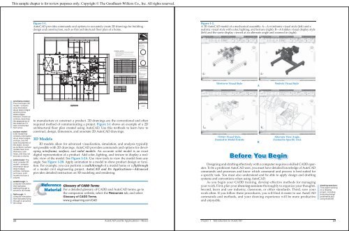
3D models allow for advanced visualization, simulation, and analysis typically<br />
not possible with 2D drawings. Au<strong>to</strong>CAD provides commands and options for developing<br />
wireframe, surface, and solid models. An accurate solid model is an exact<br />
digital representation of a product. Add color, lighting, and texture <strong>to</strong> display a realistic<br />
view of the model. See Figure 1-2A. Use view <strong>to</strong>ols <strong>to</strong> view the model from any<br />
angle. See Figure 1-2B. Apply animation <strong>to</strong> a model <strong>to</strong> show product design or function.<br />
For example, you can perform a walkthrough of a model home or a flythrough<br />
of a model civil engineering project. Au<strong>to</strong>CAD and Its Applications—Advanced<br />
provides detailed instruction on 3D modeling and rendering.<br />
Reference Glossary of CADD Terms<br />
Material For a detailed glossary of CADD and Au<strong>to</strong>CAD terms, go <strong>to</strong><br />
the companion website, select the Resources tab, and select<br />
Glossary of CADD Terms.<br />
www.g-wlearning.com/CAD<br />
22 Au<strong>to</strong>CAD and Its Applications—Basics<br />
A<br />
SD<br />
2'-10 1 2 "<br />
BRM<br />
8<br />
CABLE<br />
9<br />
CLOSET<br />
6 6<br />
A<br />
CABLE<br />
11<br />
SD<br />
6' UP WALL<br />
7<br />
6<br />
BEDROOM #3<br />
10/10 X 10/7<br />
WALK-IN CLOSET<br />
SD<br />
B B<br />
5'<br />
FIBERGLASS<br />
TUB /<br />
SHOWER<br />
BEDROOM #2<br />
10/0 X 10/5<br />
10<br />
CLOSET<br />
6'-0"<br />
D<br />
A<br />
3'-9 1 4 "<br />
3'-91 4 "<br />
7'-6 1 2 "<br />
5'-5"<br />
5'-5"<br />
10'-10"<br />
5'-5 3 4 "<br />
5'-4 1 2 "<br />
2'-9 1 4 "<br />
4'-0"<br />
32'-0"<br />
11'-0"<br />
47'-0"<br />
GENERAL NOTES<br />
1. ALL PENETRATIONS IN TOP OR BOTTOM PLATES FOR PLUMBING OR<br />
ELECTRICAL RUNS TO BE SEALED. SEE ELECTRICAL PLANS FOR<br />
ADDITIONAL SPECIFICATIONS.<br />
2. PROVIDE 1/2" WATERPROOF GYPSUM BOARD AROUND ALL TUBS,<br />
SHOWERS, AND SPAS.<br />
3. VENT DRYER AND ALL FANS TO OUTSIDE AIR THRU VENT WITH DAMPER.<br />
DOOR SCHEDULE<br />
SIZE MODEL SYMBOL QUANTITY<br />
1 3'-0" X 6'-8" SEE FRONT ELEVATION 1<br />
2 6'-0" X 6'-8" WOOD FRAME-TEMP SLDG GL 1<br />
3 3'-0" X 6'-8" SC SELF-CLOSING 1<br />
4 1<br />
3'-0" X 6'-8" SC RP METAL INSULATED<br />
5 16'-0" X 10'-0" OVERHEAD GARAGE<br />
6 2'-8" X 6'-8"<br />
1<br />
6<br />
7 2'-6" X 6'-8"<br />
HC<br />
HC 2<br />
8 2'-0" X 6'-8" HC<br />
9 5'-0" X 6'-8"<br />
1<br />
BIFOLD 1<br />
10 5'-0" X 6'-8" SLIDING 1<br />
11 2'-6" X 6'-8" POCKET 1<br />
WINDOW SCHEDULE<br />
SIZE MODEL ROUGH OPENING SYMBOL QUANTITY<br />
A 6'-0" X 4'-0" G646 SLDG 6'-0 1 2 " X 4'-01" 3<br />
B 4'-0" X 4'-0" G446 SLDG<br />
2<br />
4'-0 1 2 " X 4'-61" 1<br />
2<br />
C G644 SLDG 6'-0" X 4'-0" 6'-0 1 2 " X 4'-01" 2<br />
D 4'-0" X 2'-0" G426 SLDG<br />
2<br />
4'-0 1 2 " X 2'-05" 8<br />
1<br />
AREAS<br />
HEATED 1381 SF<br />
GARAGE 677 SF<br />
FRONT PORCH 40 SF<br />
REAR PORCH 192 SF<br />
www.madsendesigns.com<br />
CONSULTANTS<br />
Structural Engineer<br />
4570 Structure Road<br />
Building, IL 60477-6243<br />
PHONE: 800.323.0440<br />
FAX: 888.409.3900<br />
Electrical Engineer<br />
2520 Electric Road<br />
Power, IL 60477-6243<br />
PHONE: 800.323.0440<br />
FAX: 888.409.3900<br />
GOODHEART-<br />
WILLCOX RESIDENCE<br />
18604 West Creek Drive<br />
Tinley Park, IL 60477-6243<br />
OWNER<br />
<strong>Goodheart</strong>-<strong>Willcox</strong> Publisher<br />
18604 West Creek Drive<br />
Tinley Park, IL 60477-6243<br />
PHONE: 800.323.0440<br />
FAX: 888.409.3900<br />
www.g-w.com<br />
ISSUES<br />
MARK DATE DESCRIPTION<br />
MANAGEMENT<br />
PROJECT NUMBER: MDI-10001<br />
FILE NAME: A-101<br />
DRAWN BY: DPM<br />
CHECKED BY: DAM<br />
COPYRIGHT: GOODHEART-WILLCOX<br />
TITLE<br />
FLOOR PLAN<br />
SHEET<br />
A-101<br />
SHEET 3 OF 16<br />
Figure 1-2.<br />
A 3D Au<strong>to</strong>CAD model of a mechanical assembly. A—A wireframe visual style (left) and a<br />
realistic visual style with color, lighting, and texture (right). B—A hidden visual display style<br />
(left) and the same display viewed at an alternate angle and zoomed in (right).<br />
Wireframe Visual Style<br />
Hidden Visual Style,<br />
Zoomed <strong>to</strong> Model Extents<br />
A<br />
B<br />
Realistic Visual Style<br />
Before You Begin<br />
Alternate View Angle,<br />
Zoomed <strong>to</strong> Specific Area<br />
Designing and drafting effectively with a computer requires a skilled CADD opera<strong>to</strong>r.<br />
To be a profi cient Au<strong>to</strong>CAD user, you must have detailed knowledge of Au<strong>to</strong>CAD<br />
commands and processes and know which command and process is best suited for<br />
a specifi c task. You must also understand and be able <strong>to</strong> apply design and drafting<br />
systems and conventions when using Au<strong>to</strong>CAD.<br />
As you begin your CADD training, develop effective methods for managing<br />
your work. First, plan your drawing sessions thoroughly <strong>to</strong> organize your thoughts.<br />
Second, learn and use industry, classroom, or offi ce standards. Third, save your<br />
work often. If you follow these procedures, you will fi nd it easier <strong>to</strong> use Au<strong>to</strong>CAD<br />
commands and methods, and your drawing experience will be more productive<br />
and enjoyable.<br />
drawing sessions:<br />
Time spent working<br />
on a drawing<br />
project, including<br />
analyzing design<br />
parameters and<br />
using Au<strong>to</strong>CAD.<br />
<strong>Chapter</strong> 1 <strong>Introduction</strong> <strong>to</strong> Au<strong>to</strong>CAD 23