TECHNICAL APPENDIX TABLE OF FLOW RESISTANCE IN 100 m OF STRAIGHT CAST IRON PIPELINE (HAZEN-WILLIAMS FORMULA C=100) FLOW RATE NOMINAL DIAMETER in mm and INCHES m 3 /h l/min 15 20 25 32 40 50 65 80 100 125 150 175 200 250 300 350 400 1/2" 3/4" 1" 1 1/4" 1 1/2" 2 2 1/2" 3" 4" 5" 6" 7" 8" 10" 12" 14" 16" 0,6 10 v 0,94 0,53 0,34 0,21 0,13 hr 16 3,94 1,33 0,40 0,13 The hr values must be multiplied by: 0,9 15 v 1,42 0,80 0,51 0,31 0,20 0.71 for galvanized or painted steel pipes hr 33,9 8,35 2,82 0,85 0,29 0.54 for stainless steel or copper pipes 1,2 20 v 1,89 1,06 0,68 0,41 0,27 0,17 0.47 for PVC or PE pipes hr 57,7 14,21 4,79 1,44 0,49 0,16 1,5 25 v 2,36 1,33 0,85 0,52 0,33 0,21 hr 87,2 21,5 7,24 2,18 0,73 0,25 1,8 30 v 2,83 1,59 1,02 0,62 0,40 0,25 hr 122 30,1 10,1 3,05 1,03 0,35 2,1 35 v 3,30 1,86 1,19 0,73 0,46 0,30 hr 162 40,0 13,5 4,06 1,37 0,46 2,4 40 v 2,12 1,36 0,83 0,53 0,34 0,20 hr 51,2 17,3 5,19 1,75 0,59 0,16 3 50 v 2,65 1,70 1,04 0,66 0,42 0,25 hr 77,4 26,1 7,85 2,65 0,89 0,25 3,6 60 v 3,18 2,04 1,24 0,80 0,51 0,30 hr 108 36,6 11,0 3,71 1,25 0,35 4,2 70 v 3,72 2,38 1,45 0,93 0,59 0,35 hr 144 48,7 14,6 4,93 1,66 0,46 4,8 80 v 4,25 2,72 1,66 1,06 0,68 0,40 hr 185 62,3 18,7 6,32 2,13 0,59 5,4 6 90 100 v v 3,06 3,40 1,87 2,07 1,19 1,33 0,76 0,85 0,45 0,50 0,30 0,33 hr hr 77,5 94,1 23,3 28,3 7,85 9,54 2,65 3,22 0,74 0,90 0,27 0,33 7,5 9 125 150 v v 4,25 3,11 2,59 1,99 1,66 1,27 1,06 0,75 0,63 0,50 0,41 0,32 hr hr 142 59,9 42,8 20,2 14,4 6,82 4,86 1,90 1,36 0,69 0,49 0,23 10,5 175 v 3,63 2,32 1,49 0,88 0,58 0,37 hr 79,7 26,9 9,07 2,53 0,92 0,31 12 200 v 4,15 2,65 1,70 1,01 0,66 0,42 hr 102 34,4 11,6 3,23 1,18 0,40 15 18 250 300 v v 5,18 3,98 3,32 2,55 2,12 1,51 1,26 1,00 0,83 0,64 0,53 0,41 0,34 hr hr 154 72,8 52,0 24,6 17,5 6,85 4,89 2,49 1,78 0,84 0,60 0,28 0,20 24 30 36 42 400 500 600 700 v v v v 5,31 6,63 5,10 5,94 3,40 4,25 3,02 3,52 2,01 2,51 1,99 2,32 1,33 1,66 1,27 1,49 0,85 1,06 0,82 0,95 0,54 0,68 0,57 0,66 0,38 0,47 0,42 0,49 hr hr hr hr 124 187 88,6 118 41,8 63,2 24,7 32,8 11,66 17,6 8,98 11,9 4,24 6,41 3,03 4,03 1,43 2,16 1,02 1,36 0,48 0,73 0,42 0,56 0,20 0,30 0,20 0,26 48 54 800 900 v v 6,79 7,64 4,02 4,52 2,65 2,99 1,70 1,91 1,09 1,22 0,75 0,85 0,55 0,62 hr hr 151 188 42,0 52,3 15,3 19,0 5,16 6,41 1,74 2,16 0,72 0,89 0,34 0,42 60 1000 v 5,03 3,32 2,12 1,36 0,94 0,69 0,53 hr 63,5 23,1 7,79 2,63 1,08 0,51 0,27 75 1250 v 6,28 4,15 2,65 1,70 1,18 0,87 0,66 hr 96,0 34,9 11,8 3,97 1,63 0,77 0,40 90 105 1500 1750 v v 7,54 8,79 4,98 5,81 3,18 3,72 2,04 2,38 1,42 1,65 1,04 1,21 0,80 0,93 hr hr 134 179 48,9 65,1 16,5 21,9 5,57 7,40 2,29 3,05 1,08 1,44 0,56 0,75 120 2000 v 6,63 4,25 2,72 1,89 1,39 1,06 0,68 hr 83,3 28,1 9,48 3,90 1,84 0,96 0,32 150 2500 v 8,29 5,31 3,40 2,36 1,73 1,33 0,85 hr 126 42,5 14,3 5,89 2,78 1,45 0,49 180 3000 v 6,37 4,08 2,83 2,08 1,59 1,02 0,71 hr 59,5 20,1 8,26 3,90 2,03 0,69 0,28 210 3500 v 7,43 4,76 3,30 2,43 1,86 1,19 0,83 hr 79,1 26,7 11,0 5,18 2,71 0,91 0,38 240 4000 v 8,49 5,44 3,77 2,77 2,12 1,36 0,94 hr 101 34,2 14,1 6,64 3,46 1,17 0,48 300 5000 v 6,79 4,72 3,47 2,65 1,70 1,18 hr 51,6 21,2 10,0 5,23 1,77 0,73 360 6000 v 8,15 5,66 4,16 3,18 2,04 1,42 hr 72,3 29,8 14,1 7,33 2,47 1,02 420 7000 v 6,61 4,85 3,72 2,38 1,65 1,21 hr 39,6 18,7 9,75 3,29 1,35 0,64 480 8000 v 7,55 5,55 4,25 2,72 1,89 1,39 hr 50,7 23,9 12,49 4,21 1,73 0,82 540 9000 v 8,49 6,24 4,78 3,06 2,12 1,56 1,19 hr 63,0 29,8 15,5 5,24 2,16 1,02 0,53 600 10000 G-at-pct_a_th v 6,93 5,31 3,40 2,36 1,73 1,33 hr 36,2 18,9 6,36 2,62 1,24 0,65 hr = flow resistance for 100m of straight pipeline (m) V = water speed (m/s) 78
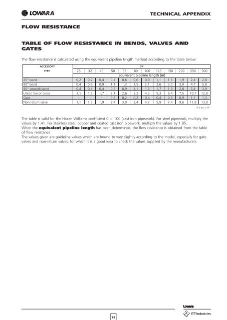
TECHNICAL APPENDIX FLOW RESISTANCE TABLE OF FLOW RESISTANCE IN BENDS, VALVES AND GATES The flow resistance is calculated using the equivalent pipeline length method according to the table below: ACCESSORY TYPE 25 32 40 50 65 80 100 125 150 200 250 300 Equivalent pipeline length (m) 45° bend 0,2 0,2 0,4 0,4 0,6 0,6 0,9 1,1 1,5 1,9 2,4 2,8 90° bend 0,4 0,6 0,9 1,1 1,3 1,5 2,1 2,6 3,0 3,9 4,7 5,8 90° smooth bend 0,4 0,4 0,4 0,6 0,9 1,1 1,3 1,7 1,9 2,8 3,4 3,9 Union tee or cross 1,1 1,3 1,7 2,1 2,6 3,2 4,3 5,3 6,4 7,5 10,7 12,8 Gate - - - 0,2 0,2 0,2 0,4 0,4 0,6 0,9 1,1 1,3 Non return valve 1,1 1,5 1,9 2,4 3,0 3,4 4,7 5,9 7,4 9,6 11,8 13,9 DN G-a-pcv_a_th The table is valid for the Hazen Williams coefficient C = 100 (cast iron pipework). For steel pipework, multiply the values by 1.41. For stainless steel, copper and coated cast iron pipework, multiply the values by 1.85. When the equivalent pipeline length has been determined, the flow resistance is obtained from the table of flow resistance. The values given are guideline values which are bound to vary slightly according to the model, especially for gate valves and non-return valves, for which it is a good idea to check the values supplied by the manufacturers. 79