100-50-5.2 - Sporlan Online
100-50-5.2 - Sporlan Online
100-50-5.2 - Sporlan Online

You also want an ePaper? Increase the reach of your titles
YUMPU automatically turns print PDFs into web optimized ePapers that Google loves.
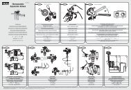
APPENDIX J - Sensor Installation<br />
Refer to Appendix I - Wiring Diagram for sensor locations.<br />
Mount the Pressure Transducer<br />
1. Position the suction return gas pressure access port near<br />
the outlet of the heat exchanger.<br />
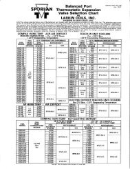
2. Verify that the pressure range matches the expected system<br />
operating pressure (i.e 0-1<strong>50</strong> psig, 0-300 psig, etc).<br />
3. Install transducer on access port at 12 o’clock, minimizing<br />
distance from temperature sensor. Check for leaks.<br />
4. For safety, ensure Schrader core is installed in access<br />
fitting (only if ¼” SAE is used). Use caution when removing<br />
Schrader cap to avoid contacting expanding<br />
refrigerant.<br />
5. Connect pressure transducer cable to transducer.<br />
6. Route and secure transducer cable away from hot surfaces<br />
and high power A/C voltage lines.<br />
7. Attach wires to the Subcool Control.<br />
8. Ensure pressure range and type (i.e gauge or absolute) are<br />
configured properly in the Subcool Controller, See Section<br />
2 - SETUP, page 4.<br />
9. After startup, use a gauge set to verify proper pressure<br />
reading through the Subcool Control. An improperly<br />
installed Schrader core can cause erroneous pressure<br />
readings.<br />
10. Check for leaks after system is in operation.<br />
Mount the Temperature Sensors – Suction and<br />
Liquid<br />
1. Per Appendix I - Wiring Diagram, page 14, measure and<br />
mark locations on copper pipe. Position sensors 10-14<br />
inches from the heat exchanger on a free-draining horizontal<br />
line.<br />
2. Remove all insulation and adhesives at the marked location.<br />
Using Scotch-Brite TM , clean the copper line to remove<br />
oxides and dirt. This will increase sensor accuracy.<br />
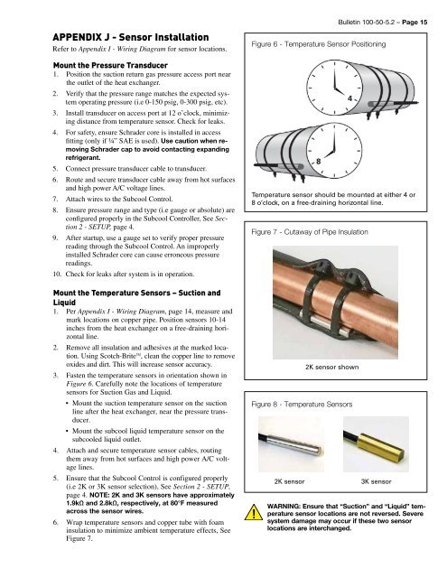
3. Fasten the temperature sensors in orientation shown in<br />
Figure 6. Carefully note the locations of temperature<br />
sensors for Suction Gas and Liquid.<br />
• Mount the suction temperature sensor on the suction<br />
line after the heat exchanger, near the pressure transducer.<br />
• Mount the subcool liquid temperature sensor on the<br />
subcooled liquid outlet.<br />
4. Attach and secure temperature sensor cables, routing<br />
them away from hot surfaces and high power A/C voltage<br />
lines.<br />
5. Ensure that the Subcool Control is configured properly<br />
(i.e 2K or 3K sensor selection), See Section 2 - SETUP,<br />
page 4. NOTE: 2K and 3K sensors have approximately<br />
1.9kΩ and 2.8kΩ, respectively, at 80°F measured<br />
across the sensor wires.<br />
6. Wrap temperature sensors and copper tube with foam<br />
insulation to minimize ambient temperature effects, See<br />
Figure 7.<br />
Bulletin <strong>100</strong>-<strong>50</strong>-<strong>5.2</strong> – Page 15<br />
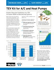
Figure 6 - Temperature Sensor Positioning<br />
Temperature sensor should be mounted at either 4 or<br />
8 o’clock, on a free-draining horizontal line.<br />
Figure 7 - Cutaway of Pipe Insulation<br />
2K sensor shown<br />
Figure 8 - Temperature Sensors<br />
2K sensor<br />
3K sensor<br />
WARNING: Ensure that “Suction” and “Liquid” temperature<br />
sensor locations are not reversed. Severe<br />
system damage may occur if these two sensor<br />
locations are interchanged.