100-50-5.2 - Sporlan Online
100-50-5.2 - Sporlan Online
100-50-5.2 - Sporlan Online

You also want an ePaper? Increase the reach of your titles
YUMPU automatically turns print PDFs into web optimized ePapers that Google loves.
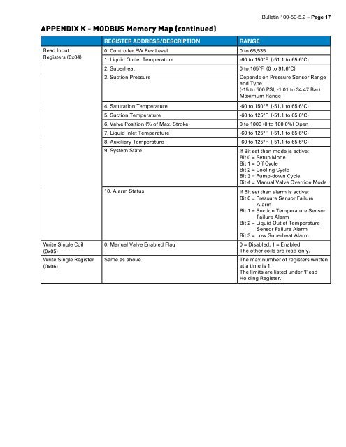
APPENDIX K - MODBUS Memory Map (continued)<br />
Bulletin <strong>100</strong>-<strong>50</strong>-<strong>5.2</strong> – Page 17<br />
Read Input<br />
Registers (0x04)<br />
Write Single Coil<br />
(0x05)<br />
Write Single Register<br />
(0x06)<br />
Register Address/Description<br />
Range<br />
0. Controller FW Rev Level 0 to 65,535<br />
1. Liquid Outlet Temperature -60 to 1<strong>50</strong>°F (-51.1 to 65.6°C)<br />
2. Superheat 0 to 165°F (0 to 91.6°C)<br />
3. Suction Pressure Depends on Pressure Sensor Range<br />
and Type<br />
(-15 to <strong>50</strong>0 PSI, -1.01 to 34.47 Bar)<br />
Maximum Range<br />
4. Saturation Temperature -60 to 1<strong>50</strong>°F (-51.1 to 65.6°C)<br />
5. Suction Temperature -60 to 125°F (-51.1 to 65.6°C)<br />
6. Valve Position (% of Max. Stroke) 0 to <strong>100</strong>0 (0 to <strong>100</strong>.0%) Open<br />
7. Liquid Inlet Temperature -60 to 125°F (-51.1 to 65.6°C)<br />
8. Auxiliary Temperature -60 to 125°F (-51.1 to 65.6°C)<br />
9. System State If Bit set then mode is active:<br />
Bit 0 = Setup Mode<br />
Bit 1 = Off Cycle<br />
Bit 2 = Cooling Cycle<br />
Bit 3 = Pump-down Cycle<br />
Bit 4 = Manual Valve Override Mode<br />
10. Alarm Status If Bit set then alarm is active:<br />
Bit 0 = Pressure Sensor Failure<br />
Alarm<br />
Bit 1 = Suction Temperature Sensor<br />
Failure Alarm<br />
Bit 2 = Liquid Outlet Temperature<br />
Sensor Failure Alarm<br />
Bit 3 = Low Superheat Alarm<br />
0. Manual Valve Enabled Flag 0 = Disabled, 1 = Enabled<br />
The other coils are read-only.<br />
Same as above.<br />
The max number of registers written<br />
at a time is 1.<br />
The limits are listed under ‘Read<br />
Holding Register.’