

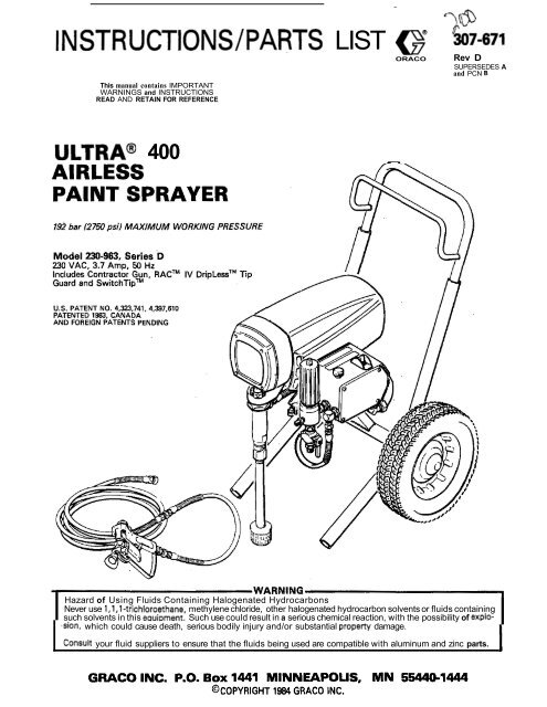
307671D ULTRA 400 AIRLESS PAINT SPRAYER - Graco Inc.
307671D ULTRA 400 AIRLESS PAINT SPRAYER - Graco Inc.
307671D ULTRA 400 AIRLESS PAINT SPRAYER - Graco Inc.

Create successful ePaper yourself
Turn your PDF publications into a flip-book with our unique Google optimized e-Paper software.
INSTRUCTIONS/PARTS LIST e 507-671<br />
This manual contains IMPORTANT<br />
WARNINGS and INSTRUCTIONS<br />
READ AND RETAIN FOR REFERENCE<br />
ORACO<br />
Rev D<br />
SUPERSEDES A<br />
and PCN B<br />
<strong>ULTRA</strong>@ <strong>400</strong><br />
I<br />
Hazard of Using Fluids Containing Halogenated Hydrocarbons<br />
I<br />
Never use l,l,l-tnchloroethane, methylene chloride, other halogenated hydrocarbon solvents or fluids containing<br />
such solvents in this eauimnent. Such use could result in a serious chemical reaction, with the possibility of explo-<br />
.sion, which could cause death, serious bodily injury and/or substantial property damage.<br />
Consult your fluid suppliers to ensure that the fluids being used are compatible with aluminum and zinc parts.
INDEX<br />
WARNINGS .................................................. 2 . 3<br />
INTRODUCTION ................................................ 4<br />
SETUP ............................................................. 5<br />
OPERATION; ................................................. 6. 7<br />
SHUTDOWN 8 CARE ......................................... 7<br />
FLUSHING GUIDELINES ..................................... 8<br />
TROUBLESHOOTING GUIDE<br />
Motor Won't Operate ................................... 9-11<br />
Low output .................................................. 12<br />
No Output ............................................... 12. 13<br />
Excessive Pressure Fluctuations ......................... 13<br />
Motor Is Hot and Runs Intermittently .................. 13<br />
Electrical Short ...................................... :....... 14<br />
Spin Test ..................................................... 15<br />
Bridge Test ................................................... 16<br />
REPAIR SECTION<br />
General Repair Notes ...................................... 17<br />
List of Tools .................................................. 17<br />
Power Supply Cord Replacement ....................... 18<br />
Filter Replacement ......................................... 18<br />
ON/OFF Switch Replacement ........................... 19<br />
Microswitch Replacement ................................ 19<br />
Bridge Rectifier Replacement ............................ 20<br />
Choke Replacement ........................................ 21<br />
Varistor Replacement ...................................... 21<br />
Circuit Board Replacement ............................... 22<br />
Pressure Control Replacement .......................... 23<br />
Stall Pressure Calibration ................................. 24<br />
Connecting Rod. Drive Housing or Crankshaft<br />
Replacement ............................................ 25. 26<br />
Motor Brush Replacement ................................ 27<br />
Motor Capacitor Replacement ........................... 28<br />
Motor Replacement ................................... 29. 30<br />
PARTS LISTS 8 DRAWINGS<br />
Sprayer .................................................. 32. 33<br />
Pressure Control ....................................... 34. 35<br />
How To Order Replacement Parts ...................... 33<br />
............................... Back Cover<br />
TECHNICAL DATA<br />
NOTE: See manual 307.793. supplied. for the<br />
displacement pump repair instructions and<br />
parts list .<br />
307-671 1
~~<br />
~<br />
HIGH PRESSURE SPRAY CAN CAUSE EXTREMELY SERIOUS INJURY.<br />
FOR PROFESSIONAL USE ONLY. OBSERVE ALL WARNINGS.<br />
Read and understand all instruction manuals, tags, and warnings before operating equipment.<br />
FLUID INJECTION HAZARD<br />
General Safety<br />
This equipment generates very high fluid pressure. Spray from<br />
the gun, leaks or ruptured components can inject fluid<br />
through your skin and into your body and cause extremely<br />
serious bodily injury, including the need for amputation. Also,<br />
fluid injected or splashed into the eyes or onto the skin can<br />
cause serious damage.<br />
NEVER point the spray gun at anyone or any part of the body.<br />
NEVER put hand or fingers over the spray tip. NEVER try to<br />
“blow back” paint; this is NOT an air spray system.<br />
ALWAYS have the tip guard in place on the spray gun when<br />
spraying.<br />
~. ~~<br />
ALWAYS follow the Pressure Relief Procedure. below.<br />
before cleaning or removing the spray tip or servicing any<br />
system equipment.<br />
NEVER try to.stop or deflect leaks with your hand or body.<br />
Be sure equipment safety devices are operating properly<br />
before each use.<br />
Medical Alert-Airless Spray Wounds<br />
If any fluid appears to penetrate your skin, get EMERGENCY<br />
MEDICAL CARE AT ONCE. DO NOT TREAT AS A<br />
SIMPLE CUT. Tell the doctor exactly what fluid was injected.<br />
Note to Physician: injection in the skin is a traumatic injury.<br />
It Is important to treat the injury surgically as soon<br />
as possible. Do not delay treatment to research toxiciry.<br />
Toxicity is a concern with some exotic coatings injected<br />
directly into the blood stream. Consultation with a plastic<br />
surgeon or reconstructive hand surgeon may be advisable.<br />
Spray Gun Safety Devices<br />
Be sure all gun safety devices are operating properly before<br />
each use. Do not remove or modify any part of the gun; this<br />
can cause a malfunction and result in serious bodily injury.<br />
Safety Latch<br />
Whenever you stop spraying, even for a moment, always set<br />
the gun safety latch in the closed or “safe” position, making<br />
the gun inoperative. Failure to set the safety latch can result in<br />
accidental triggering of the gun.<br />
Diffuser<br />
The gun diffuser breaks up spray and reduces the risk of fluid<br />
injection when the tip is not installed. Check diffuser operation<br />
regularly. Follow the Pressure Relief Procedure, below,<br />
then remove the spray tip. Aim the gun into a metal pail,<br />
holding the gun firmly to the pail. Using the lowest possible<br />
pressure, trigger the gun. If the fluid emitted is not diffused into<br />
an irregular stream, replace the diffuser immediately.<br />
Tip Guard<br />
ALWAYS have the tip guard in place on the spray gun while<br />
spraying. The tip guard alerts you to the fluid injection hazard<br />
and helps reduce, but does not prevent, the risk of accidentally<br />
placing your fingers or any part of your body close to the<br />
spray tip.<br />
Spray Tip Safety<br />
Use extreme caution when cleaning or changing spray tips. If<br />
the spray tip clogs while spraying, engage the gun safety latch<br />
immediately. ALWAYS follow the Pressure Relief Procedure<br />
and then remove the spray tip to clean it.<br />
NEVER wipe off build-up around the spray tip until pressure is<br />
fully relieved and the gun safety latch is engaged.<br />
Pressure Relief Procedure<br />
To reduce the risk of serious bodily injury, including fluid injection, injury from splashing fluid or solvent in the eyes or on the<br />
skin, moving parts or electric shock, always follow this procedure whenever you shut off the sprayer, when checking or servicing<br />
any part of the spray system, when installing, cleaning or changing spray tips, and whenever you stop spraying. (11 Engage<br />
the gun safety latch. (21 Turn the ON/OFF switch to OFF. (31 Unplug the power supply cord. (4) Disengage the gun safety latch.<br />
(51 Hold a metal pan of the gun firmly to the side of a grounded metal pail, and trigger the gun to relieve pressure. (61 Engage the<br />
gun safety latch. 17) Open the drain valve, having a container ready to catch the drainage. 181 Leave the drain valve open until<br />
you are ready to spray again.<br />
If you suspect that the spray tip or hose is completely clogged, or that pressure has not been fully relieved after following the<br />
steps above, VERY SLOWLY loosen the tip guard retaining nut or hose end coupling and relieve pressure gradually, then loosen<br />
completely. Now clear the tip or hose.<br />
I<br />
ENGAGE SAFETY<br />
IATCH<br />
TURN SWITCH TO OFF<br />
UNPLUG CORD<br />
DISENGAGE SAFETX<br />
ANDTRIGGERQUN:<br />
ENGAGE SAFETY AGAIN<br />
OPEN DRAIN VALVE<br />
I<br />
2 307-671
EQUIPMENT MISUSE HAZARD<br />
General Safety<br />
Any misuse of the spray equipment or accessories, such as<br />
overpressurizing, modifying parts, using incompatible<br />
chemicals and fluids, or using worn or damaged parts, can<br />
cause them to rupture and result in fluid injection or other<br />
serious bodily injury, fire, explosion or property damage.<br />
NEVER alter or modify any part of this equipment; doing so<br />
could cause it to malfunction.<br />
CHECK all spray equipment regularly and repair or replace<br />
worn or damaged parts immediately.<br />
Read and follow the fluid and solvent manufacturer's literature<br />
regarding the use of protective clothing and equipment. ,<br />
System Pressure<br />
This sprayer can develop 192 bar (2750 psi) MAXIMUM<br />
WORKING PRESSURE. Be sure that all spray equipment and<br />
accessories are rated to withstand the maximum working<br />
pressure of this sprayer. DO NOT exceed the maximum working<br />
pressure of any component or accessory used in the<br />
system.<br />
Fluid Compatibility<br />
BE SURE that a11 fluids and solvents used are chemically compatible<br />
with the wetted parts shown in the Technical Data on<br />
the back cover. Always read the fluid and solvent manufacturer's<br />
literature before using them in this sprayer.<br />
HOSE SAFETY<br />
High pressure fluid in the hoses can be very dangerous.' If the<br />
hose develops a leak, split or rupture due to any kind of wear,<br />
damage or misuse, the high pressure spray emitted from it can<br />
cause a fluid injection injury or other serious bodily injury or<br />
property damage.<br />
ALL FLUID HOSES MUST HAVE SPRING GUARDS ON<br />
BOTH ENDS1 The spring guards help protect the hose from<br />
kinks or bends at or close to the coupling which can result in<br />
hose rupture.<br />
TIGHTEN all fluid connections.securely before each use. High<br />
pressure fluid can dislodge a loose coupling or allow high<br />
pressure spray to be emitted from the coupling.<br />
NEVER use a damaged hose. Before each use, check the entire<br />
hose for cuts, leaks, abrasion, bulging cover, or damage or<br />
movement of the hose couplings. If any of these conditions<br />
exist, replace the hose immediately. DO NOT try to recouple<br />
high pressure hose or mend it with tape or any other device. A<br />
repaired hose cannot contain the high pressure fluid.<br />
HANDLE AND ROUTE HOSES CAREFULLY. Do not pull on<br />
hoses to move equipment. Do not use fluids or solvents which<br />
are not comoatible with the inner tube and cover of the hose.<br />
DO NOT expose <strong>Graco</strong> hose to temperatures above 820C<br />
1180°F) or below -4OOC (-4OOF).<br />
Hose Grounding Continuity<br />
Proper hose grounding continuity is essential to maintaining a<br />
grounded spray system. Check the electrical resistance of your<br />
air and fluid hoses at least once a week. If your hose does not<br />
have a tag on it which specifies the maximum electrical<br />
resistance, contact the hose supplier ormanufacturer for the<br />
maximum resistance limits. Use a resistance meter in the appropriate<br />
range for your hose to check the resistance. If the<br />
resistance exceeds the recommended limits, replace it immediately.<br />
An ungrounded or poorly grounded hose can make<br />
your system hazardous. Also read FIRE OR EXPLOSION<br />
HAZARD.<br />
FIRE OR EXPLOSION HAZARD<br />
Static electricity is created by the flow of fluid through the<br />
pump and hose. If every pan of the spray equipment is not<br />
properly grounded, sparking may occur, and the system may<br />
become hazardous. Sparking may also occur when plugging<br />
in or unplugging a power supply cord. Sparks can ignite fumes<br />
from solvents and the fluid being sprayed, dust particles and<br />
other flammable substances. whether you are spraying indoors<br />
or outdoors, and can cause a fire or explosion and<br />
serious bodily injury and property damage. Always plug the<br />
sprayer into an outlet at least 6 m I20 feet) away from the<br />
sprayer and the spray area. Do not plug in or unplug any<br />
power supply cords in the spray area when there is any chance<br />
of igniting fumes still in the air.<br />
If you experience any static sparking or even a slight shock<br />
while using this equipment, STOP SPRAYING IMMEDI-<br />
ATELY. Check the entire system for proper grounding. Do not<br />
use the system again until the problem has been identified and<br />
corrected.<br />
Grounding<br />
To reduce the risk of static sparking, ground the sprayer and<br />
all other spray equipment used or located in the spray area.<br />
CHECK your local electrical code for detailed grounding instructions<br />
for your area and type of equipment, BE SURE to<br />
ground all of this spray equipment:<br />
1.<br />
2.<br />
3.<br />
4.<br />
5.<br />
6.<br />
7.<br />
IMPORTANT<br />
Sprayer: plug the power supply cord, or extension cord,<br />
each equipped with an undamaged three-prong plug, into<br />
a properly grounded outlet. Do not use an adapter. All extension<br />
cords must have three wires and be rated for 15<br />
amps.<br />
Fluid hoses: use only grounded hoses with a maximum of<br />
500 feet 1150 m) combined hose length to ensure grounding<br />
continuity. Refer to Hose Grounding Continuity.<br />
Spray gun: obtain grounding through connection to a<br />
properly grounded fluid hose and sprayer.<br />
Fluid supply container: according to local code.<br />
Object being Sprayed: according to local code.<br />
All solvent pails used when flushing, according to local<br />
code. Use only metalpails, which are conductive. Do not<br />
place the pail on a non-conductive surface, such aspaper<br />
or cardboard, which interrupts the grounding continuity.<br />
To maintain grounding continuity when flushing orrelievingpressure,<br />
always hold a metal part of the gun firmly to<br />
the side of a grounded metal pail, then trigger the gun.<br />
Flushing Safety<br />
Reduce the risk of fluid injection injury, static sparking, or<br />
splashing by following the specific flushing procedure given<br />
on page 0 of this manual. Follow the Pressure Relief Procedure<br />
on page 2, and remove the spray tip before flushing.<br />
Hold a metal part of the gun firmly to the side of a metal pail<br />
and use the lowest possible fluid pressure during flushing.<br />
MOVING PARTS HAZARD<br />
Moving parts can pinch or amputate your fingers or other<br />
body parts. KEEP CLEAR of moving parts when starting or<br />
operating the sprayer. Unplug the sprayer, and follow the<br />
Pressure Relief Procedure on page 2 to prevent it from starting<br />
accidentally.<br />
United States Government safety standards have been adopted under the Occupational Safety and Health Act. These standards-particularly<br />
the General Standards, Part 1910, and the Construction Standards, Pan 1926-should be consulted.<br />
307-671 3
Your new Ultra" <strong>400</strong> Sprayer functions and operates<br />
differently than other airless paint sprayers. This section<br />
will help you become familiar with the sprayer before<br />
operating it.<br />
Pressure Control<br />
The pressure control includes an ONlOFF switch for the<br />
sprayer, the pressure adjusting control knob, and a<br />
pressure sensing device. Its function is to control the<br />
motor speed so that the sprayer maintains constant<br />
fluid pressure at the pump outlet.<br />
Motor<br />
The DC motor has sealed bearings and replaceable<br />
motor brushes. Its function is to drive the displacement<br />
pump at the rate needed to supply sufficient .paint<br />
volume at the selected pressure.<br />
Working together, the pressure control and motor<br />
cause the pump to cycle whenever there is fluid or<br />
pressure demand. When the pump is cycling, the motor<br />
sounds like an automobile starter cranking. When the<br />
pump is not cycling, the motor may hum intermittently<br />
until the fluid pressure stabilizes, then the motor will<br />
shut itself off. However, there will still be power to the<br />
sprayer and it will stay pressurized and ready to use<br />
unless you manually shut it off and relieve pressure.<br />
Because the motor is DC, it is less sensitive to low<br />
voltage or voltage fluctuations than an AC motor, and<br />
an extension cord of up to 45 m (150 feet) can be used.<br />
Displacement Pump<br />
The positive displacement, volume-balanced pump provides<br />
equal fluid delivery'on both the up and down<br />
pump strokes. The pump has a wet-cup which, when<br />
filled with <strong>Graco</strong> Throat Seal Liquid, helps prevent<br />
damage to the throat packings and piston rod.<br />
Fluid Filter<br />
The fluid filter provides the final paint straining to help<br />
avoid clogs in the hose and spray tip. The filter includes<br />
a reusable element and a drain valve for relieving fluid<br />
pressure when shutting off the sprayer.<br />
Hoses<br />
Two grounded, nylon spray hoses with spring guards<br />
are included with the sprayer. The 15.2 m (50foot) hose<br />
has a 114 in. ID. The 0.9 m (3 foot), 3/16 in. ID whip<br />
hose allows flexible gun movement. The nylon hose<br />
material acts as a pulsation dampener to absorb<br />
pressure fluctuations.<br />
Spray Gun & Reverse-A-CleanTM IV DripLessTM Tip<br />
Guard<br />
The spray gun includes a trigger safety latch which<br />
prevents accidental triggering when it is engaged (see<br />
the WARNING on page 2) and a trigger guard which<br />
prevents accidental triggering if the gun is dropped. The<br />
Reverse-A-Clean IV SwitchTipTM uses high pressure<br />
fluid to remove clogs from the spray tip without removing<br />
it from the gun. It includes a safety tip guard which<br />
helps reduce the risk of fluid injection injury.<br />
Drive Assembly<br />
The sealed drive assembly transfers power from the DC<br />
motor to the displacement pump.<br />
4 307-671
~~<br />
~ ~~<br />
SETUP<br />
1. Connect Hose and Gun (Refer to Fig 1.)<br />
NOTE:<br />
When tightening fittings at the pressure control,<br />
hold one wrench firmly on the hex of<br />
the pressure control fitting to keep it from<br />
rotating. Use another wrench to tighten the<br />
mating fitting.<br />
a. Remove the plastic cap plug from the filter<br />
outlet nipple and tightly screw the 15.2 m (50 ft)<br />
fluid hose onto the nipple.<br />
b. Tightly connect the whip hose between the<br />
fluid hose and the gun inlet connection.<br />
c. Don't use thread sealant on swivel couplings.<br />
The sealant can prevent the swivel from<br />
rotating freely.<br />
d. Don't install the spray tip yet1<br />
IcA<br />
To avoid damaging the pressure control, which<br />
may result in poor equipment performance and<br />
component damage, follow these precautlons:<br />
1. Always use nylon spray hose at least 15.2<br />
m ( 50 ft) long.<br />
2. Never use a wire braid hose as it is too rigid<br />
to act as a pulsation dampener.<br />
3. Never install any shutoff device between<br />
the filter and the main hose. See Flg 1.<br />
4. Always use the main filter outlet for onegun<br />
operation. Never plug this outlet.<br />
2. Fill Packing Nutiwet-Cup (See Fig 2.)<br />
Fill the packing nut/wet-cup 1/3 full with <strong>Graco</strong><br />
Throat Seal Liquid (TSL), supplied.<br />
3. Check Electrical Service<br />
a. Be sure the electrical service is properly rated<br />
for your sprayer and that the outlet you use Is<br />
properly grounded.<br />
b. Attach an appropriate plug to the power supply<br />
cord, according to your local electrical codes.<br />
c. Use an extension cord which has 3 wires of a<br />
minimum 12 gauge size, and a maximum of<br />
45 m (150 ft) long. Longer lengths may affect<br />
sprayer performance.<br />
4. Plug in the Sprayer<br />
a. Be sure the ONlOFF switch is OFF. 'Refer to<br />
Fig 3. Then plug the cord into a grounded electrical<br />
outlet at least 6 m (20 ft) away from the<br />
spray area.<br />
WARNING<br />
Proper electrical grounding is essential to reduce<br />
the risk of fire or explosion which can result in<br />
serious bodily.injury and property damage. Refer<br />
to the warning section FIRE OR EXPLOSION<br />
HAZARD on page 3 for more detailed grounding<br />
instructlons.<br />
5. Flush the pump to remove the lightweight oil<br />
which was left in to protect pump parts after factory<br />
testing.<br />
a. Before using water-base paint, flush with<br />
mineral spirits followed by soapy water, and<br />
then a clean water flush.<br />
b. Before using oil-base painr, flush with mineral<br />
spirits only.<br />
c. See "Flushing Guidalines" on page 8 for<br />
flushing procedure.<br />
6. Prepare the paint according to the manufacturer's<br />
recommendations.<br />
a. Remove any skin that may have formed.<br />
b. Stir the paint to dissolve hard pigments.<br />
c. Strain the paint through 5 fine nylon mesh bag<br />
(available at most paint dealers) to remove particks<br />
that could clog the filter or spray tip. This<br />
is probably the mosr importanr step toward<br />
trouble-free spray painting,<br />
307-671 6
OPERATION<br />
WARNING<br />
Pressure Relief Procedure<br />
To reduce the risk of serious bodily injury, including<br />
fluid injection, injury from splashing fluid<br />
or solvent in the eyes or on the skin, moving parts<br />
or electric shock, always follow this procedure<br />
whenever you shut off the sprayer, when checking<br />
or servicing any part of the spray system,<br />
when installing, cleaning or changing spray tips,<br />
and whenever you stop spraying.<br />
1. Engage the gun safety latch.<br />
2. Turn the ON/OFF switch to OFF.<br />
3. Unplug the power supply cord.<br />
4. Disengage the gun safety latch.<br />
5. Hold a metal part of the gun firmly to the<br />
side of a grounded metal pail, and trigger<br />
the gun to relieve pressure.<br />
6. Engage the gun safety latch.<br />
7. Open the filter drain valve, having a container<br />
ready to catch the drainage.<br />
8. Leave the drain valve open until you are<br />
ready to operate the sprayer again.<br />
Prime the Sprayer with Paint.<br />
a. Close the filter drain valve.<br />
b. Don't install the spray tip yet1<br />
c. Put the suction tube into the paint container.<br />
d. Turn the pressure adjusting knob all the way<br />
counterclockwise to the lowest pressure setting.<br />
e. Disengage the gun safety latch.<br />
f. Hold a metal part of the gun firmly against and<br />
aimed into a metal waste container.. See Fig 4.<br />
Squeeze the trigger and hold it open, turn the<br />
ON/OFF switch to ON, and slowly increase the<br />
pressure setting until the sprayer starts. Keep<br />
the gun triggered until all air is forced out of the<br />
system and the paint flows freely from the gun.<br />
Release the trigger and engage the safety.<br />
Fig 4<br />
3. Adjusting the Spray Pattern<br />
a. <strong>Inc</strong>rease the pressure adjusting knob setting<br />
just until spray from the gun is completely<br />
atomized. To avoid excessive overspray and<br />
fogging, and to decrease tip wear and extend<br />
the life of the sprayer, always use the lowest<br />
possible pressure needed to get the desired<br />
results.<br />
b. If more coverage is needed, use a larger tip<br />
rather than increasing the pressure.<br />
c. Test the spray pattern. To adjust the direction<br />
of the spray pattern, engage the gun safety and<br />
loosen the retaining nut. Position the tip guard<br />
horizontally for a horizontal pattern or vertically<br />
for a vertical pattern. Then tighten the retaining<br />
nut.<br />
NOTE:<br />
If the pump is hard to prime, place a container<br />
under the drain valve and open the<br />
drain valve. When fluid comes from the<br />
valve, close it. Then disengage the gun<br />
safety and proceed as in Step If, above.<br />
4. Check all fluid connections for leaks. If any are<br />
found, follow the Pressure Relief Procedure<br />
Warning, above, before tightening connections.<br />
2. Install the Spray Tip and Tip Guard<br />
a. Be sure the gun safety latch is engaged.<br />
b. Install the spray tip. If using the RAC IV, refer<br />
to manual 307-848, supplied with the gun, for<br />
installation instructions.<br />
6 307-671
4. Cleaning a Clogged Tip<br />
WARNING<br />
To avoid a fluid injection injury, DO NOT hold<br />
your hand, body, or a rag in front of the spray tip<br />
when cleaning or checking a clogged tip. Always<br />
point the gun toward .the ground or into a waste<br />
container when checking to see if the tup IS clear.<br />
DO NOT try to "blow back" paint; this is NOT an<br />
air spray sprayer.<br />
a. Clean the front of the tip frequently during the<br />
day's operation. First, follow the Pressure<br />
Relief Procedure Warning on page 6. Then<br />
use a solvent-soaked brush to keep fluid from<br />
building up and clogging the tip.<br />
ENGAGETHE<br />
TRIGGER SAFETY<br />
LATCH BY TURNING<br />
LATCH PERPENDICUI AR<br />
TO QUN BODY<br />
b. If the spray tip does clog, release the gun trigger,<br />
engage the gun safety, and rotate the<br />
RAC IV handle 180°. See Fig 5.<br />
Fig 5<br />
c. Disengage the gun safety and trigger the gun<br />
into a waste container. Engage the gun safety<br />
again.<br />
d., Return the handle to the original position,<br />
disengage the gun safety, and resume spraying.<br />
e. if the tip is stili dogged, engage the gun safety,<br />
shutoff and unplug the sprayer, and open the<br />
drain valve to relieve pressure. Clean the spray<br />
tip as shown in manual 307-848, supplied with<br />
the RAC IV DripLess tip guard.<br />
SHUTDOWN AND CARE<br />
1. Check the packing nutlwet-cup daily. First<br />
follow the Pressure Relief Procedure Warning<br />
on page 6. Be sure the wet-cup is 113 full of TSL at<br />
all times to help prevent fluid buildup on the piston<br />
rod and premature wear of packings. The packing<br />
nut should be tight enough to stop leakage, but no<br />
tighter. Overtightening may cause binding and excessive<br />
packing wear. Use a screwdriver and light<br />
hammer to adjust the nut. See Fig 6.<br />
2. Clean the fluid filter often and whenever the<br />
sprayer is stored. First follow the Pressure Relief<br />
Procedure Warning on page 6. Refer to manual<br />
307-273, supplied, for the cleaning procedure.<br />
3. Lubricate the bearing housing after every 100<br />
hours of operation. Fill the cavity of the bearing<br />
housing with SAE 10 nondetergent oil.<br />
4. Flush the sprayer at the end of each work day<br />
and fill it with mineral spirits to help prevent pump<br />
corrosion and freezing. See "Flushing Guidelines"<br />
on page 0.<br />
Fig 6<br />
6. Coil the hose and hang it on the hose rack when<br />
storing it, even for overnight, to help protect the<br />
hose from kinking, abrasion, coupling damage, etc.<br />
rW<br />
Refer to the warning section HOSE SAFETY on<br />
page 3 for information on the hazard of using<br />
damaged hoses.<br />
chance of fluid freezing in the pump or pressure<br />
control in cold weather, never leave water or any<br />
type of paint in the sprayer when it is not in use.<br />
Freezing can seriously damage the sprayer and<br />
result in loss of pressure or stalling.<br />
5. For vary short shutoff periods, leave the suction<br />
tube in the paint, follow the Pressure Relief Procedure<br />
Warning on page 6, and clean the spray<br />
tip.<br />
307-671 7
FLUSHING GUIDELINES<br />
When to Flush<br />
1. New Sprayer. Your new UltraQ <strong>400</strong> Sprayer was<br />
factory tested in lightweight motor'oil which was<br />
left in to protect pump parts.<br />
Before using water-base paint, flush with mineral<br />
spirits, followed by soapy water, and then a clean<br />
water flush.<br />
Before using oil-base pain!, flush with mineral<br />
spirits only.<br />
2. Changing Colors. Flush with*a compatible solvent<br />
such as mineral spirits or water.<br />
3. Changing from water-base to oil-base paint.<br />
Flush with soapy water, then minera1,spirits.<br />
4. Changing from oil-base to water-base paint.<br />
Flush with mineral spirits, followed by soapy water,<br />
then a clean water flush.<br />
5. Storage.<br />
Water-base paint: flush with water, then mineral<br />
spirits and leave the pump, hose and gun filled with<br />
mineral spirits. Shutoff and unplug the sprayer,<br />
open the drain valve to relieve pressure and leave<br />
open.<br />
Oil-base paint: flush with mineral spirits. Shutoff<br />
and unplug the sprayer, open the drain valve to<br />
relieve pressure and leave open.<br />
6. Startup after storage.<br />
Before using water-base paint, flush out mineral<br />
spirits with soapy water and then a clean water<br />
flush.<br />
When using oil-base paint, flush out the mineral<br />
spirits with the fluid to be sprayed and the sprayer is<br />
ready to use.<br />
How to Flush<br />
1. Follow the Pressure Relief Procedure Warning<br />
on page 6. '<br />
2. Remove the filter bowl and screen; see manual<br />
307-273 supplied. Clean the screen separately and<br />
install the bowl without the screen.<br />
FILTER<br />
BOWL<br />
SCREEN<br />
FILTER<br />
SUPPORT<br />
MAINTAIN FIRM<br />
METAL TO METAL<br />
CONTACT WHEN<br />
Fig 7<br />
DRAIN VALVE<br />
4 SHOWN OPEN<br />
3. Close the filter drain valve.<br />
4. Pour 2 liters (112 gal.) of compatible solvent into a<br />
bare metal pail. Put the suction tube in the pail.<br />
Fig 8<br />
Always remove the spray tip from the gun before<br />
IWAR<br />
flushing to reduce the risk of a fluid injection in- 9. Unplug the power supply cord. Open the drain<br />
5. Disengage the gun safety latch.<br />
6. Point the spray gun into a grounded metal waste<br />
container and with a metal part of the gun firmly<br />
touching the metal container, squeeze the gun trigger.<br />
This procedure helps avoid static sparking<br />
which can cause fire or explosion and splashing.<br />
With the gun triggered, turn the ONIOFF switch to<br />
ON and slowly turn the pressure adjusting knob<br />
clockwise just until the sprayer starts. Keep the<br />
gun triggered until clean solvent comes from the<br />
nozzle. Release the trigger and engage the gun<br />
safety latch.<br />
8 307-671<br />
7. Check all fluid connections for leaks. If any leak,<br />
follow the Pressure Relief Procedure Warning<br />
on page 6. Now tighten the connections, start the<br />
sprayer, and recheck the connections for leaks.<br />
8. Remove the suction tube from the pail. Disengage<br />
the gun safety and trigger the gun to force solvent<br />
from the hose. Do not let the pump run dry for<br />
more than 30 seconds to avoid damaging the<br />
pressure control. Then turn ON/OFF switch to<br />
OFF and engage the gun safety latch.<br />
valve and leave open until you are ready to use the<br />
sprayer again. Unscrew the filter bowl and reinstall<br />
the clean screen. Reinstall the bowl, hand tight<br />
only.<br />
10. If you have flushed with mineral spirits and are going<br />
to use a water-base paint, flush with soapy<br />
water followed by a clean water flush. Then repeat<br />
Step 1.
~~<br />
TROUBLESHOOTING GUIDE<br />
-<br />
-<br />
-<br />
-<br />
i 1<br />
WARNING<br />
Pressure Relief Procedure<br />
To reduce the risk of serious .bodilv injury. in- 6. Engage the gun safety latch.<br />
cluding fluid injection, splashing fluid in ihe eyes 7. Ooen the drain valve. havina a container readv<br />
I<br />
or on the skin, or injury from moving parts or elec- to catch the drainage.<br />
tric shock, always follow this procedure whenever<br />
8. Leave the drain valve open until you are ready<br />
you shut off the sprayer, when checkingor servicto<br />
spray again.<br />
ing any part of the spray system, when Installing,<br />
cleaning or changing spray tips, and whenever If you suspect that the spray tip or hose is comyou<br />
stop spraying.<br />
pletely clogged, or thatpressure has not been fully<br />
relieved after following the steps above, VERY<br />
1. Engage the gun safety latch.<br />
SLOWLY loosen the tip guard retaining nut or<br />
2. Turn the ON/OFF switch to OFF.<br />
hose end couolina and relieve oressure araduallv.<br />
3. Unplug the power supply cord. then loosen comphely. Nowciearthe tip or hosb:<br />
4. Disengage the gun safety latch.<br />
5. Hold a metal part of the gun firmly to the side of<br />
a grounded metal pail, and3rigger the gun to<br />
relieve pressure.<br />
TYPE OF PROBLEM<br />
MOTOR WONT OPERATE<br />
Basic Fluid Pressure Problems<br />
Basic Mechanical Problems<br />
Basic Electrical Problems<br />
WHAT TO CHECK<br />
If check is OK, go to next check<br />
1. Check the pressure control knob sening.<br />
The motor will not run if it is at the<br />
minimum sening (fully<br />
counterclockwise).<br />
2. Check for a clogged spray tip. Refer to<br />
your separate gun or tip instruction<br />
manual.<br />
1. Check for frozen or hardened paint in<br />
the pump (19) andlor pressure control<br />
bourdon tube. Using a screwdriver,<br />
carefully try to rotate fan at back of<br />
motor. See page 15.<br />
2. Check displacement pump connecting<br />
rod pin (m). It must be completely<br />
pushed into connecting rod (91 and<br />
spring retainer (21) should be firmly in<br />
groove of connecting rod. See page 26.<br />
3. Check for motor damage. Remove drive<br />
housing assembly (6). See page 25. Try<br />
to rotate fan bv hand.<br />
1. Check electrical supply with volt meter.<br />
Meter should read 190-250 Volts.<br />
2. Check extension cord for visible<br />
damage. Use a volt meter or test lamp<br />
m extension cord outlet to check.<br />
3. Check sprayer power supply cord (311)<br />
for visible damage such as broken insulation<br />
or wires.<br />
4. Check motor brush leads, terminals and<br />
brush length. Brush length should be<br />
14 mm minimum. See DaQe 28.<br />
'Thaw the sprayer if water or water-based paint has frozen in<br />
it, due to exposure to low temperatures, by placing it in a<br />
warm area. Do not try to start the sprayer until it has thawed<br />
completely. If the bourdon tube was not damaged by the<br />
freezing, the pump should operate. If paint hardened (dried1 in<br />
the sprayer. the pump packings and/or bare pressure control<br />
mum be replaced. See page 23 or manual 307-793.<br />
I~~~~<br />
WHAT.TO DO<br />
If check is NOT OK refer to this column<br />
1. Slowly increase the pressure setting to<br />
see if the motor starts.<br />
2. Relieve pressure, refer to your separate<br />
gun or tip instruction manual for tip<br />
cleaning.<br />
1. Thaw'. Plug in sprayer and turn on.<br />
Slowly increase pressure setting to see if<br />
motor starts. If it doesn't, replace the<br />
displacement pump packings (see<br />
manual 307-793) andlor replace the bare<br />
pressure control box (3011'. See page<br />
23.<br />
2. Push pin into place and secure with the<br />
spring retainer.<br />
3. Replace motor I1 1 if fan won't turn.<br />
1. Reset building circuit breaker; replace<br />
building fuse. Try another electrical<br />
outlet.<br />
2. Replace extension cord.<br />
3. Replace power supply cord.<br />
See page 18.<br />
4. lighten terminal screws; replace<br />
brushes. See page 27.<br />
'When replacing the bare pressure control box (item 301).<br />
remove the ONlOFF switch, bridge, circuit board and electrical<br />
hardware and reinstall these parts in the bare box.<br />
Troubleshooting continued on next page.<br />
307-671 9
~~~~~~<br />
TYPE OF PROBLEM<br />
MOTOR WON7 OPERATE<br />
Diagnosing circuit board indicator<br />
lamps. The normal<br />
condition is red lamp on,<br />
clear lamp on when board is<br />
telling pump to run.<br />
Follow Pressure Relief Procedure<br />
Warning. Remove<br />
gun from hose. Remove<br />
pressure control cover and<br />
check for faulty condition of<br />
circuit board lamps.<br />
Condition A both lamps on;<br />
pump won't operate and<br />
motor is not running<br />
Condition B<br />
Both lamps off<br />
WHAT TO CHECK<br />
If check Is OK, go to next check<br />
I. Check leads from bridge 1308) to motor<br />
to be sure they are securely fastened<br />
and properly mated.<br />
1. Check G1 and G2 connections between<br />
circuit board ( 3401 and bridge 1308) for<br />
damage or loose terminals.<br />
3. Check for loose motor brush lead connections<br />
and terminals. See page 27.<br />
4. Check brush length which should be 14<br />
mm minimum. See page 27.<br />
NOTE also that the brushes do not wear<br />
at the same rate on both sides of the<br />
motor.<br />
5. Check for broken or misaligned motor<br />
brush springs. Rolled portion of spring<br />
must rest squarely on top of brush. See<br />
page 27.<br />
6. Check motor brus'hes for binding in<br />
brush holders. See page 27.<br />
7. Check motor armature commutator for<br />
burn spots, gouges and axtreme<br />
rouohness. Remove motor cover and<br />
brush inspection plates to check. See<br />
page 27.<br />
6. Check motor armature for shorts using<br />
armature tester (growler) or perform spin<br />
test. See page 15.<br />
9. Check bridge 1 308) by substituting with<br />
a good bridge or performing bridge test.<br />
See page 16.<br />
CAUTION: DO not perform this check<br />
until armature is determined to be good.<br />
A bad armature will immediately burn<br />
out a good bridge.<br />
1. Check electrical supply. Connect<br />
voltmeter to electrical outlet. Meter<br />
should read 190.250 Volts.<br />
2. Check power supply to circuit board<br />
with sprayer turned ON. Measure<br />
voltage at TPl and TP2. Meter should<br />
read 190-250 Volts. See page 7.2.<br />
WHAT TO DO<br />
If check is NOT OK refer to this column<br />
1. Replace any loose terminals and crimp<br />
to leads. Be sure male terminal blades<br />
are straight and firmly connected to<br />
mating part.<br />
2. Clean circuit board male terminals.<br />
Replace loose or damaged terminals.<br />
Securely reconnect leads.<br />
3. Tighten terminal screws. Replace<br />
brushes if leads are damaged.<br />
See page 27.<br />
4. Replace brushes. See page 27.<br />
5. Replace spring if broken. Realign spring<br />
with brush. See page 27.<br />
6. Clean brush holders. Remove carbon<br />
with small cleaning brush. Align brush<br />
lead with slot in brush holder to assure<br />
free vertical brush movement.<br />
7. Remove motor and have motor shop<br />
resurface commutator if possible. See<br />
page 27.<br />
8. Replace motor. See page 29.<br />
9. Replace bridge. See page 20.<br />
1. Reset circuit breaker or replace outlet<br />
fuse. If circuit breaker or fuse continues<br />
to open, see "Electrical Short", page 14.<br />
2. Unplug sprayer. Check continuity of<br />
both poles of ONlOFF switch (302) from<br />
TPl to TPZ, and TP2 to TP3. Replace<br />
switch if faulty.<br />
Check continuity of RFI filter (3101 from<br />
TP4 to TP6 and TP3 to TP5. Replace<br />
filter if faulty.<br />
Check power supply cord (3111 for continuity<br />
from TP5 to TP7 and TP6 to TP8.<br />
Replace cord if faulty.<br />
10 307-671<br />
3. Check a11 terminals and wires fog<br />
damage or loose fit.<br />
4. Check motor thermal cutout switch.<br />
Unplug sprayer. Allow motor to cool.<br />
Disconnect motor thermal switch leads<br />
at TP9 to TPlO. Use ohmmeter to check<br />
continuity. Switch should be closed<br />
when motor is cool.<br />
3. Replace damaged terminals and reconnect<br />
securely.<br />
4. Replace electric motor if switch does not<br />
close when motor is cool. See page 29.
YPE OF PROBLEM<br />
Condition B<br />
(continued)<br />
Condition C<br />
Red lamp on, clear lamp off<br />
Unplug sprayer1<br />
WHAT TO CHECK<br />
f check is OK, go to next check<br />
i. Check microswitch 1306). With no fluid<br />
pressure in the pressure control disconnect<br />
wires TP18 and TP19. Check continuity<br />
across switch terminals with an<br />
ohmmeter. Switch contact should be<br />
closed. Depress actuator bunon. An<br />
audible "click" indicates the contacts<br />
have opened. Ohmmeter should read infinity.<br />
i. Check circuit board (3401 by substituting<br />
with a good board. See page 22.<br />
. Check circuit board (3401 by removing<br />
from box wirhout disconnecting wires;<br />
sea page 22 for removal procedure.<br />
WHAT TO DO<br />
If check is NOT OK refer to this colurn<br />
5. Replace microswitch. See page 19.<br />
3, Replace circuit board. See page 22.<br />
I. Replace circuit board. Sea page 22.<br />
WARNING: Removing the circuit board<br />
while still wired over-rides the optical<br />
detector which could cause the sprayer<br />
. to over-pressurize, if the microswitch<br />
does not function properly. Tum the<br />
sprayer on ONLY long enough to check<br />
lamp condition, then shut off immediately.<br />
WARNING: To reduce the risk of electric<br />
shock, handle board by edges only1<br />
Do not allow any metal objects to come<br />
in contacl with the boardl<br />
Plug in and turn on sprayer. Clear lamp<br />
should be on now - removing the circuit<br />
board over-rides the optical detector.<br />
Turn off and unplug sprayer.<br />
!. Check bourdon tube flag and detector<br />
position. Reinstall circuit board ( see page<br />
22. Turn pressure setting to maximum;<br />
flag should extend less than half way into<br />
optical detector slot from the bonom.<br />
2. Calibrate pressure control to sea if that<br />
corrects problem. See page 24.<br />
If not, replace bare pressure control box<br />
13011'. See page 23.<br />
DETECTOR<br />
CIRCUIT-<br />
BOARD<br />
VIEW OF OPTICAL DETECTOR AND FLAG<br />
'When replacing the bare pressire control box 13011. remow the ON/OFFswitch, bridge,<br />
circuit board and elecbical hardware and reinstall in the new bare box.<br />
Tmubleshooting continued on next page.<br />
307-671 11
~~<br />
TYPE OF PROBLEM<br />
WHAT TO CHECK<br />
If check is OK. go to next check<br />
WHAT TO DO<br />
If check is NOT OK refer to this column<br />
LOW OUTPUT<br />
NO OUTPUT<br />
Motor runs and pump stroke:<br />
307-671<br />
1. Check for worn spray tip.<br />
2. Check to see that pump does not continue<br />
to stroke when gun trigger is<br />
released. Plug in and turn on sprayer.<br />
Prime with paint. Trigger gun momentarily,<br />
then release and engage safety<br />
latch. Relieve pressure, turn off and<br />
unplug sprayer.<br />
3. Check electrical supply with volt meter.<br />
Meter should read 190-250 Volts.<br />
4. Check extension cord size and length;<br />
must be at least 12 gauge wire and no<br />
longer than 15.2 m (150 ft).<br />
5. Check G1 and G2 leads from bridge<br />
WX) to circuit board 1340) for damage<br />
or loose wires or connectors. Refer to<br />
page 22.<br />
6. Check stall pressure. Refer to Calibration<br />
Procedure on page 24.<br />
7. Check bridge (308) + and - leads and<br />
terminals to motor. Inspect wiring insulation<br />
and terminals for signs of<br />
overheating. See page 20.<br />
8. Check for loose motor brush leads and<br />
terminals. See page 27.<br />
9. Check for worn motor brushes which<br />
should be 14 mm (9/16) minimum. See<br />
pBge 27.<br />
10.Check for broken and misaligned motor<br />
brush springs. Rolled portion of spring<br />
must rest squarely on top of brush.<br />
11.Check motor brushes for binding in<br />
brush holders. See page 27.<br />
12.Check circuit board 1 340) by substituting<br />
with a good circuit board. See page 22.<br />
13.Check motor armature for shorn by using<br />
an armature tester (growler) or perform<br />
spin test. See page 15.<br />
14.Check bridge ( 308) by substituting with<br />
a good bridge or by performing the<br />
bridge test. See page 16 or 20.<br />
CAUTION: Do not perform this check<br />
until armature is determined to be good.<br />
A bad armature will immediately burn<br />
out a good bridge.<br />
1. Check paint supply.<br />
2. Check for clogged intake strainer.<br />
3. Check for loose suction tube or fittings.<br />
1. Follow Pressure Relief Procedure<br />
Warning then replace tip. See your<br />
separate gun or tip manual.<br />
2. Service pump. See manual 307-793.<br />
3. Reset building circuit breaker; replace<br />
building fuse. Repair electrical outlet or<br />
try another outlet.<br />
4. Replace with a correct, grounded extension<br />
cord.<br />
5. Clean circuit board male terminals.<br />
Replace loose or defective lead terminals.<br />
Securely reconnect lead terminals<br />
to board.<br />
6. Calibrate pressure control. See page 24.<br />
7. Be sure male terminal blades are<br />
centered and firmly connected to female<br />
terminals. Replace any loose terminal or<br />
damaged wiring. Securely reconnect<br />
wires to bridge.<br />
8. Tighten terminal screws. Replace<br />
brushes if leads are damaged. See page<br />
27.<br />
9. Replace brushes. See page 27.<br />
10.Replace spring if broken. Realign spring<br />
with brush. See page 27.<br />
11 .Clean brush holders, remove carbon<br />
dust with small cleaning brush. Align<br />
brush lead with slot in brush holder to<br />
assure free vertical brush movement.<br />
12.Replace circuit board. See page 22.<br />
13.Replace motor. See page 29.<br />
14.Repiace bridge. See page 20.<br />
1. Refill and reprime pump.<br />
2. Remove and clean, then reinstall.<br />
3. Tighten; use thread sealant or sealing<br />
tape on threads if necessary.
TYPE OF PROBLEM<br />
NO OUTPUT<br />
(Continued)<br />
Motor runs but pump does<br />
not stroke<br />
WHAT TO CHECK<br />
If check is OK, go to next check<br />
, Check to see if intake valve ball and<br />
piston ball are seating properly. See<br />
manual 307-793.<br />
. Check for leaking around throat packing<br />
nut which may indicate worn or damaged<br />
packings.See manual 307-793.<br />
. Check displacement pump connecting<br />
rod pin. See page 26.<br />
, Check connecting rod assembly for<br />
damage. See page 25.<br />
. Be sure crank in drive housing rotates;<br />
plug in sprayer and turn on momentarily<br />
to check. Turn off and unplug sprayer.<br />
See page 25.<br />
WHAT TO DO<br />
If check is NOT OK refer to this column<br />
,. Remove intake valve and clean. Check<br />
balls and seats for nicks; replace if<br />
necessary. See manual 307-793.<br />
#. Replace packings. See manual 307-793.<br />
Also check piston valve seat for hardened<br />
paint or nicks and replace if<br />
necessarv.<br />
. Replace pin if missing. Be sure retainer<br />
spring is fully in groove a11 around<br />
connecting rod. See page 26.<br />
!. Replace connecting rod assembly. See<br />
page 25.<br />
i. Check drive housino assemblv for<br />
damage and replac; if necessary. See<br />
page 25.<br />
EXCESSIVE PRESSURE<br />
FLUCTUATIONS<br />
Spray panern variations.<br />
. Be sure both G1 and G2 leads from<br />
bridge 1308) to circuit board 13401 are<br />
firmly connected. See page 22.<br />
'. Check stall pressure. Refer to Calibration<br />
procedure on page 24.<br />
i. Check bourdon tube flag and detector<br />
position. Turn pressure sening to maximum;<br />
flag should not drag or bind in<br />
optical detector slot of circuit board.<br />
r CIRCU'TBoARD<br />
"<br />
. Reconnect securely. See page 22.<br />
I. Calibrate pressure control. See page 24.<br />
I. Carefully bend flag into alignment with<br />
detector slot to see if that corrects problem.<br />
If not, replace bare pressure control<br />
assembly (3011'. Calibrate pressure control<br />
after reassembly.<br />
OPTICAL<br />
DETECTOR<br />
MOTOR IS HOT e<br />
RUNS INTERMllTENTLY<br />
FLAG<br />
VIEW OF OPTICAL DETECTOR AND FLAG<br />
I. Check circuit board ( 3401 by substituting<br />
with a good board. See page 22.<br />
i. Check LOW OUTPUT section on page<br />
12.<br />
. Check to see if sprayer has been<br />
operating at high pressure with small<br />
tips, which causes low motor RPM and<br />
results in excessive heat build up.<br />
I. Check to see if ambient temperature<br />
where sprayer is located is more than<br />
32% (90°F) or if sprayer is located in<br />
direct sun.<br />
!. Check to see if sprayer has been left in a<br />
stalled condition [sprayer turned on,<br />
pressurized, but not operating) for long<br />
periods of time.<br />
I. Replace circuit board. See page 22.<br />
I. Decrease pressure sening or increase tip<br />
size.<br />
!. Move sprayer<br />
possible.<br />
to shaded, coolel ' area if<br />
1. Turn off sprayer whenever you stop<br />
spraying for awhile and relieve fluid<br />
pressure.<br />
307-671 13
TYPE OF PROBLEM<br />
ELECTRICAL SHORT<br />
WHAT TO CHECK<br />
If check is OK, go to next check<br />
WHAT TO DO<br />
If check Is NOT OK refer to this column<br />
Buildino circuit breaker ooens<br />
as sooi as sprayer switch is<br />
turned on.<br />
CAUTION<br />
Any short in any part of thf<br />
motor power circuit, which i$<br />
connected to the output sidc<br />
of the bridge, will cause thf<br />
bridge to burn out immediate<br />
ly. Correctly diagnose anc<br />
repair all shorts before check,<br />
ing and replacing bridge<br />
Building circuit breaker opens<br />
as soon as sprayer is plugged<br />
into outlet and sprayer is NO1<br />
turned on.<br />
Check all electrical wiring for damaged<br />
insulation, and all terminals for loose fit<br />
or damage. Be sure to check wires between<br />
pressure control and motor which<br />
are encased in conduit 141 I. See page<br />
29.<br />
1. Repair or replace any damaged wiring or<br />
terminals. Securelv reconnect all wires.<br />
, Check for missing inspection plate 2. Correct faulty conditions.<br />
gasket (see page 27). bent terminal forks<br />
or other metal to metal contact points<br />
which could cause a short.<br />
Check motor armature for shorts by us- 3. Replace motor. See page 29.<br />
ing an armature tester (growler) or perform<br />
spin test. See page 15. Inspect<br />
windings for bums.<br />
, Check bridge ( 3081 by substituting with 4. Replace bridge. See page 2 0.<br />
a good bridge or by performing bridge<br />
test. See page 16.<br />
CAUTION: Do not perform this check<br />
until armature is determined to be good.<br />
A bad armature will immediately burn<br />
out a good bridge.<br />
Check 'Basic Electrical Problems' on<br />
page 9.<br />
Check ON/OFF switch 1302) See page<br />
19. Be sure the sprayer is unplugged!<br />
Disconnect wires from switch and check<br />
switch with ohm meter. The ohm meter<br />
should read infinity with the ONlOFF<br />
switch OFF, and zero with the switch<br />
ON.<br />
2. Replace ON/OFF switch. See page 19.<br />
CAUTION: A short in the motor circuit<br />
will burn the bridge out immediately,<br />
which in turn usually causes the ONlOFF<br />
switch to fail in the closed mode.<br />
14 307-671
~~~ ~~<br />
~ ~_____~<br />
SPIN TEST<br />
1<br />
WARNING<br />
Before doing this procedure, follow the Pressure<br />
Relief Procedure Warning on page 17 to reduce<br />
the risk of a fluid injection injury, splashing fluids<br />
in the eyes or on the skin, injury from moving<br />
Darts. or electric shock.<br />
For checking armature, motor winding and brush electrical<br />
continuity.<br />
Setup<br />
Remove the drive housing from the sprayer as described<br />
in Steps 1-9, page 25.<br />
Remove the pressure control cover and screws, !he<br />
motor cover, the fan cover (F), and the inspectton<br />
covers IJ). See Fig 9.<br />
Disconnect the two leads from the motor to the bridge<br />
(308). See Fig 10.<br />
Armature Short Circuit Test<br />
Quickly turn the motor fan by hand. If there are no<br />
shorts, the motor will coast two or three revolutions<br />
before coming to a complete stop.<br />
If the motor does not spin freely and resists rotation, the<br />
armature is shorted and the motor must be replaced.<br />
See page 29.<br />
Armature, Brushes, and Motor Wiring Open<br />
Circuit Test (Continuity)<br />
Connect the two black motor leads together with a test<br />
lead.<br />
Turn the motor fan by hand at about two revolutions<br />
per second.<br />
If there is uneven or no turning resistance, check the<br />
following: a) broken brush springs; b) broken brush<br />
leads; c) loose brush terminal screws; d) worn brushes;<br />
e) broken motor leads; f) loose motor lead termlnals.<br />
Repair parts as needed. See page 27.<br />
If there is still uneven or no turning resistance, replace<br />
the motor. See page 29.<br />
Fig 9<br />
307-671 15
BRIDGE TEST<br />
Remove the bridge from the pressure control box and<br />
perform this test to determine if the bridge is functional.<br />
See Bridge Rectifier Replacement, page 20. Use a<br />
continuity tester, such as multi-meter set on the X1<br />
ohms scale ( n ).<br />
Eight individual checks, or tests, must be performed. If<br />
the bridge fails even one test, it must be replaced.<br />
Fig 11 shows the position of the wires on the bridge. Using<br />
the chart at the right, connect the meter wires as indicated<br />
by the black dots for each test, then check the<br />
continuity.<br />
In Tests 1, 2 and 3, there should be NO continuity.<br />
In Tests 4, 5 and 6, connect the + and - meter wires as<br />
indicated, check continuity, then.switch the meter wire<br />
connections and check continuity again. You should<br />
get NO continuity one way, and YES continuity the<br />
other way.<br />
In Tests 7 and 8. connect the meter wires as indicated<br />
by the black dots. Touch the indicated "G" wire to one<br />
meter wire, and then the other. You should get NO continuity<br />
one way, and YES continuity the other way.<br />
BRIDGE WIRES<br />
Fig 11<br />
16 307-671
GENERAL REPAIR NOTES<br />
WARNING<br />
Pressure Relief Procedure<br />
To'reduce the risk of serious bodily injury, including<br />
fluid injection, splashing fluid in the eyes<br />
or on the skin, or injury from moving parts or electric<br />
shock, always follow this procedure whenever<br />
you shut off the sprayer, when checking or servic:<br />
ing any part of the spray system, when installing,<br />
cleaning or changing spray tips, and whenever<br />
you stop spraying.<br />
1 .Engage the gun safety latch.<br />
2 .Turn the ONIOFF switch to OFF.<br />
3 .Unplug the power supply cord.<br />
4 .Disengage the gun safety latch.<br />
5 .Hold a metal part of the gun firmly to the side of<br />
a grounded metal pail, and trigger the gun to<br />
relieve pressure.<br />
6 .Engage the gun safe& latch.<br />
7 .Open the drain valve, having a container ready<br />
to catch the drainage.<br />
8 .Leave the drain valve open until you are ready<br />
to spray again.<br />
If you suspect that the spray tip or hose is completely<br />
clogged, or that pressure has not been fully<br />
relieved after following the steps above, VERY<br />
SLOWLY loosen the tip guard retaining nut or<br />
hose end coupling and relieve pressure gradually,<br />
then loosen completely. Now clear the tip or hose.<br />
Tool List<br />
The following tools are needed when repairing this<br />
sprayer.<br />
Phillips screwdriver<br />
Small flatblade screwdriver<br />
Needle nose pliers<br />
Plastic mallet<br />
Adjustable wrench<br />
2" adjustable, open-end wrench<br />
Torque wrench<br />
114" hex key wrench<br />
3/16" hex key wrench<br />
518" socket wrench<br />
318" open end wrench<br />
112'' open end wrench<br />
314" open end wrench<br />
718" open end wrench<br />
High quality motor oil<br />
Bearing grease<br />
For calibration procedure only:<br />
318 ignition wrench<br />
0.015' spray tip<br />
High pressure, oil-filled test gauge, Part No. 102-814<br />
5 gallon pail<br />
Clean water<br />
Mineral spirits<br />
NEW 207 bar (3oM) psi) high pressure spray hose,<br />
Part No. 214-915.<br />
Before repairing any part of the sprayer, read the following<br />
general repair notes and the repair procedure. Be<br />
sure you have the necessary tools and parts available.<br />
1. When disconnecting wires in the pressure control<br />
assembly, use needle nose pliers to separate mating<br />
connectors.<br />
When reconnecting the wires, be sure the flat blade<br />
of the insulated male connector is centered in the<br />
wrap-around blade of the female connector when<br />
the connection is made.<br />
CAUTION<br />
tion, be sure to properly mate connectors, and<br />
never pull on a wire to disconnect it. Pulling on a<br />
wire could loosen the connector from the wire.<br />
2. Route wires in the pressure control assembly<br />
carefully through the legs of the U-shaped bourdon<br />
tube, where appropriate, to avoid interfering with<br />
the bourdon tube which moves as the pressure setting<br />
changes and to avoid pinching the wires between<br />
the pressure control box and cover.<br />
CAUTION<br />
Improper wire routing can result in poor sprayer<br />
performance or damage to the pressure control.<br />
3. Keep all screws, nuts, washers, gaskets, and electrical<br />
fittings removed during repair procedures.<br />
These parts are not normally provided with replacement<br />
assemblies.<br />
4. Test your repair before regular operation of the<br />
sprayer to be sure the problem is corrected.<br />
If the sprayer does not operate properly, review the<br />
repair procedure again to verify that everything was<br />
done correctly. If necessary, refer to the<br />
Troubleshooting Guide, pages 9-16, to help identify<br />
other possible problems and solutions.<br />
To reduce the risk of serious bodily injury, including<br />
electric shock, DO NOT touch any moving<br />
parts or electrical parts with your fingers or a tool<br />
while inspecting.the repair.<br />
Shut off the sprayer and unplug it as soon as you<br />
complete the inspection.<br />
Reinstall all covers, gaskets, screws and washers<br />
FW<br />
before operating the sprayer.<br />
CAUTION<br />
Do not run the sprayer dry for more than 30<br />
seconds to avoid damaging the pump packings.<br />
5. Reinstall the motor cover before regular operation<br />
of the sprayer and replace it if it is damaged. The<br />
cover directs cooling air around the motor to help<br />
prevent overheating. It can also help prevent burns,<br />
fire or explosion; see the WARNING, below.<br />
WARNING<br />
During operation, the motor becomes very hot<br />
and could burn your skin if touched. Flammable<br />
materials spilled on the hot, bare motor could<br />
cause a fire or explosion. Always have the motor<br />
cover in place during regular operation to reduce<br />
the risk of burns, fire or explosion.<br />
307-671 17
POWER SUPPLY CORD REPLACEMENT (See Fig 12 Et 131<br />
WARNING<br />
follow the Pressure<br />
Relief Procedure Warning on page 17 to reduce<br />
the risk of a fluid injection injury, splashing in the<br />
eyes or on the skin, injury from moving parts, or<br />
electric shock.<br />
1. Use the 19 mm open end wrench to remove the nut<br />
(337) from the filter stud (310).<br />
2. Use the 13 mm socket wrench to remove the two<br />
screws (651 holding the pressure control to the<br />
frame.<br />
3. Remove the pressure control mounting bracket (50)<br />
using a Phillips screwdriver.<br />
4. Disconnect the power supply cord wires from the<br />
control box terminal strip (336) using a screwdriver.<br />
5. Install the new power supply cord (3111 in the<br />
reverse order of disassembly.<br />
Install a new plug on the other end of the cord. Be Fig 12<br />
sure,to follow all local codes regarding the type of<br />
olua to use.<br />
.I<br />
FILTER REPLACEMENT (See Fig 12)<br />
WARNING<br />
Before doing this procedure, follow the Pressure<br />
Relief Procedure Warning on page 17 to reduce<br />
the risk of a fluid injection injury, splashing in the<br />
eyes or on the skin, injury from moving parts, or<br />
1. Remove the pressure control cover and screws.<br />
2. Use a needle nose pliers to remove the four wires<br />
from the filter (3101.<br />
3. Use the M8 wrench to remove the lower nut and<br />
lockwashers (337, 338) on the outside of the<br />
pressure control box.<br />
4. Remove the old filter and install a new one in the<br />
reverse order of disassembly.<br />
Fig 13<br />
18 307-671
ON/OFF SWITCH REPLACEMENT (See Figs 14 Et 15)<br />
WARNING<br />
Before doing this procedure, follow the Pressure<br />
Relief Procedure Warning on page 17 to reduce<br />
the risk of a fluid injection injury, splashing in the<br />
eyes or on the skin, injury from moving parts, or<br />
electric shock.<br />
1. Remove the pressure control cover and screws.<br />
2. Remove the wires attached to the switch (302) at<br />
TPl and TP2, using a screwdriver. See page 22, Fig<br />
21.<br />
3. Use a 16 mm socket wrench to loosen and remove<br />
the nut and rubber boot (303) from the top of the<br />
pressure control box. Remove the switch guard<br />
(304).<br />
4. Remove the ONIOFF switch.<br />
5. Remove the wires attached to the switch TP4 and<br />
TP3 using a screwdriver. See page 22, Fig 21.<br />
6. Attach the wires to TP4 and TP3 of the new switch.<br />
7. Install the new switch so the internal tab of the antirotation<br />
ring (W) engages with the vertical groove<br />
in the threads of the switch, and the external tab<br />
engages with the blind hole (D) of the pressure control<br />
box.<br />
8. Install the switch guard (304). aligning the internal<br />
tab with the groove in the threads.<br />
9. Powder the inside of the rubber boot (303) with<br />
talcum, then shake excess out of boot.<br />
10. Install the nut and rubber boot and tighten.<br />
11. Reconnect the wires to TP1 and TP2.<br />
12. Reinstall the pressure control cover and screws.<br />
Fig 14<br />
MICROSWITCH REPLACEMENT (See Fig 15)<br />
Before doing this procedure, follow the Pressure<br />
Relief Procedure Warning on page 17 to reduce<br />
the risk of a fluid injection injury, splashing in the<br />
eyes or on the skin, injury from moving parts, or<br />
1. Remove the pressure control cover and screws.<br />
2. Disconnect both wires from the microswitch (3061.<br />
3. Use the socket wrench to remove the nuts from the<br />
microswitch.<br />
4. Check to see if the flag (X) is loose. If it is, be sure<br />
the fluid pressure is 0 bar (0 psi), then loosen the<br />
two 6 mm hex nuts behind the microswitch. Adjust<br />
the distance from the top of the flat to top inside of<br />
the pressure control box to 40.79k 0.254 mm<br />
(1.606* 0.010 in.). Tighten the screwsand recheck<br />
the dimension. Refer to Fig 1.<br />
5. Perform the STALL PRESSURE CALIBRATION<br />
on page 24 before regular operation of the sprayer.<br />
6. Reinstall the cover and screws.<br />
Fig 15<br />
307-671 19
~ ~~~ ~~ ~~<br />
~~<br />
BRIDGE RECTIFIER REPLACEMENT (See Fig 161<br />
WARNING<br />
1<br />
Before doing this procedure, follow the Pressure<br />
Relief Procedure Warning on page 17 to reduce<br />
the risk of a fluid injection injury, splashing in the<br />
eyes or on the skin, injury from moving parts or<br />
electric shock.<br />
. CAUTION<br />
The lockwashers (333) must be in front of the<br />
bridge to avoid overheating which will result in<br />
bridge failure. Refer to the Detail in Fig 16.<br />
6. Make sure the bridge is flush with the side of the box<br />
and tighten the screws securely.<br />
1. Remove the pressure control cover and screws.<br />
7. Connect all wires. Carefully route the wires.<br />
2. Disconnect all wires from the bridge ( 3081 at the appropriate<br />
terminals.<br />
I- CAUTION<br />
3. Outside the pressure control box on the right side are Be sure the flat blade of the insulated male contwo<br />
screws (331). Loosen, but don't remove the nector is centered in the wrap-around blade of the<br />
screw near the back mounting plate (50). Then female connector when the connections are<br />
loosen and remove the front screw. Slide the bridge made. Improper connections may cause the<br />
out.<br />
sprayer to malfunction.<br />
4. Slide the new bridge (308) into the box being sure<br />
the lockwasher (333) on the rear screw (331) is /N<br />
FRONT of the bridge. Refer to the Detail in Fig 16.<br />
5. Install the front screw, lockwasher and nut (332).<br />
Ro'ute all wires carefully to avoid interference with<br />
the movement of the bourdon tube, circuit board,<br />
or control box cover which could cause a malfunc-<br />
8. Reinstall the pressure control cover and screws.<br />
BRIDCE INSTALLATION DETAIL<br />
Fig 16<br />
20 307-671
CHOKE REPLACEMENT (See Fig 17)<br />
1. Remove the pressure control cover and screws.<br />
2. Remove the grounding screw (312) and remove the<br />
lead. Loosen the appropriate screw on the terminal<br />
strip (336) and discornect the yellow/green choke<br />
lead.<br />
3. Use the M8 wrench to remove the upper nut and<br />
lockwasher (337, US) on the outside of the<br />
pressure control box.<br />
4. Remove the old choke (309) and install a new one in<br />
the reverse order of disassembly.<br />
Fig 17<br />
VARISTOR REPLACEMENT (See Figs 18 8 19)<br />
1.<br />
' 2.<br />
3.<br />
4.<br />
5.<br />
WARNING<br />
Relief Procedure Warning on page 17 to reduce<br />
the risk of a fluid injection injury, splashing in the<br />
eyes or on the skin, injury from moving parts, or<br />
Remove the control box screws and cover.<br />
Remove the two screws (A$). the wiring<br />
harnesses (318, 319) and the old varistor from the<br />
ONlOFF switch (302).<br />
Trim the leads on the new varistor (339) to 28.5 mm<br />
(1-118 in.). Turn each lead outward to form a loop<br />
that is large enough for the screws (A, 8) to pass<br />
through.<br />
Place a wiring harness on each screw, then place a<br />
loop of the varistor leads on each screw and thread<br />
the screws into the switch.<br />
Wrap the varistor under the switch.<br />
n<br />
FRONTVIEW<br />
n<br />
SIDEVIEW<br />
307-671 21
Step 2 is essential to reduce the risk of damaging<br />
IcA<br />
the circuit board while removing or installing it.<br />
CIRCUIT BOARD REPLACEMENT (See Figs 20 8 21)<br />
WARNING<br />
Before doing this procedure, follow the Pressure<br />
Relief Procedure Warning on page 17 to reduce<br />
the risk of a fluid injection injury, splashing in the<br />
eyes or on the skin, injury from moving parts, or<br />
electric shock. Be sure to unolua rhe soraverl<br />
1. Remove the pressure control cover and screws.<br />
2. Turn the pressure control knob all the way counterclockwise<br />
to the minimum setting to release spring<br />
tension on the board. Also check to be sure only<br />
three or four threads of the pressure control knob<br />
shaft are exposed below the pressure adjustment<br />
nut (SI. Back down the nut, if necessary. See Fig<br />
20.<br />
rClRCUlT BOARD<br />
r PRESSURE CONTROL KNOB<br />
3. Disconnect ALL wires from the board, including the<br />
two heavy black wires. Pay close attention to where<br />
connections are made. See Fig 21. .<br />
4. To remove the board from the box, pull out the<br />
- black plastic-tipped pin (330). Push the bottom of<br />
the circuit board toward the wall of the box and<br />
carefully slide the board out.<br />
5. Install the board in the box at the Same angle as it<br />
was removed.<br />
6. Reconnect all wires. Refer to the wiring diagram in<br />
Fig 21.<br />
Fig P<br />
CAUTION<br />
Be sure the flat blade of the insulated male connector<br />
is centered exactly in the wrap-around<br />
blade of the female connector when connections<br />
are made.<br />
Route all wires carefully to avoid interference with<br />
the circuit board, bourdon tube and pressure control<br />
cover.<br />
These precautions are essential to reduce the risk<br />
of malfunction.<br />
7. Perform the STALL PRESSURE CALIBRATION<br />
on page 24 if you installed a new board.<br />
Fig 21<br />
22 307-671<br />
TP8<br />
PLUQ<br />
TP7
PRESSURE CONTROL REPLACEMENT<br />
the risk of a fluid injection injury, splashing in the<br />
1. Disconnect the main fluid hose (72) and the secondary<br />
fluid hose, if used, from the sprayer.<br />
2. Disconnect the fluid hose (23) from between the<br />
displacement pump outlet nipple (22) and pressure<br />
control inlet elbow (314).<br />
3. Loosen the filter bracket nut (63) and washer (62)<br />
using a 19 mm open end wrench.<br />
4. Hold the pressure control adapter (315) firmly with<br />
a 19 mm open end wrench. Use an adjustable<br />
wrench to loosen the swivel union (52). then<br />
remove the fluid filter (53).<br />
5. Remove the pressure control cover and screws, and<br />
disconnect the four motor leads at the appropriate<br />
terminals.<br />
6. Refer to CIRCUIT BOARD REPLACEMENT on<br />
page 22, remove the circuit board and retain.<br />
7. Remove the conduit (41 1. Fig 22<br />
8. Use a 13 mm open end wrench to loosen and<br />
remove the pressure control mounting screws 165)<br />
and washers (64) located below the pressure control<br />
box. Remove the box.<br />
9. Install the new pressure control assembly in the<br />
reverse order of disassembly.<br />
CAUTION<br />
stalling the new pressure control assembly. Turning<br />
it can damage the sensitive bourdon tube.<br />
Hold the adapter firmly with a 19 mm open end<br />
10. Perform the STALL PRESSURE CALIBRATION<br />
starting on page 24, before regular operation of the<br />
sprayer.<br />
307-671 23
~ ~~<br />
STALL PRESSURE CALIBRATION<br />
I<br />
I<br />
USE<br />
WA RNlNG<br />
EXTREME CAUTION WHEN PERFORMING THIS CALIBRATION PROCEDURE to reduce the risk of a<br />
fluid injection injury or other serious bodily injury which can result from splashing, component rupture, electric<br />
shock, fire, explosion, or moving parts.<br />
This procedure sets the sprayer to 192 bar (2750 psi)<br />
MAXIMUM WORKING PRESSURE. This procedure<br />
must be performed whenever a new or used circuit<br />
board, or pressure control assembly is removed and<br />
reinstalled or replaced, to be sure the sprayer is properly<br />
calibrated.<br />
Improper calibration can cause the sprayer to overpressurize<br />
and result in component rupture, fire or<br />
explosion. It may also prevent the sprayer from obtaining<br />
the maximum working pressure which would<br />
result in poor sprayer performance.<br />
NEVER attempt to increase the fluid outlet pressure<br />
by performing this calibration in any other way.<br />
NEVER EXCEED 192 bar (2750 psi) MAXIMUM<br />
WORKING PRESSURE. Normal operation of the<br />
sprayer at higher pressures could result in component<br />
rupture, fire or explosion.<br />
AVOID touching.the wires in the pressure control<br />
assembly with your fingers or tools when the control<br />
box cover is removed to reduce the risk of electric<br />
shock.<br />
Calibration Setup (See Fig 23 and 24)<br />
1. Follow the Pressure Relief Procedure Warning<br />
on page 17. Remove the spray hose and gun. Install<br />
a 0.015' spray tip in the gun. Connect the gun to a<br />
new test hose and connect the hose to the sprayer<br />
outlet.<br />
2. Remove the pressure control screws and cover.<br />
3. Remove the plug from the top of the fluid filter, and<br />
install the test gauge (W).<br />
4. Place the pump suction tube in a 5 gallon pail of<br />
clean water.<br />
5. Be sure the gun safety latch is engaged.<br />
6. Use a 9 mm (3/8') ignition wrench to turn the<br />
pressure adjustment nut (SI counterclockwise<br />
about two full turns. See Fig 24.<br />
7. With the pressure control knob (B) at the minimum<br />
setting, turn the sprayer switch ON.<br />
THE <strong>SPRAYER</strong> SHOULD NOT STARTI<br />
If it does start, shut the. sprayer switch OFF,<br />
disengage the gun safety latch, trigger the gun into<br />
a grounded waste container until pressure is relieved.<br />
Engage the gun safety latch. Turn the pressure<br />
adjustment nut (S) a little further counterclockwise.<br />
Turn the sprayer on to be sure it does nor start.<br />
8. Slowly turn the pressure control knob (81 clockwise<br />
to the maximum setting and hold it there. Use a<br />
9 mm (3/8') ignition wrench to slowly turn the<br />
pressure adjustment nut (S) clockwise until the test<br />
gauge reads EXACTLY 192 bar (2750 psi).<br />
h WARNING Follow the Pressure Relief Procedure Warning<br />
on page 17. 1<br />
I<br />
CAUTION<br />
To prevent pump corrosion, flush the water out of<br />
the pump, hose and gun with mineral spirits. Be<br />
sure to close the drain valve, first. Use the lowest<br />
pressure necessary to flush. Follow the Pressure<br />
Relief Procedure Warning on page 17. Leave<br />
the mineral spirits in the pump to protect it until<br />
you are ready to spray again.<br />
9. Remove the'test gauge assembly and reinstall the<br />
plug. Flush out water with mineral spirits.<br />
Fig 23<br />
Fig 24<br />
24 307-671
CONNECTING ROD, DRIVE HOUSING, or CRANKSHAFT<br />
r-<br />
REPLACEMENT (See Fig 25)<br />
WARNING<br />
CAUTION<br />
Before doing this procedure, follow the Pressure<br />
DO NOT allow the gear cluster (26) to fall when<br />
Relief Procedure Warning on page 17 to reduce removing the drive housing (6). It is easiiy damagthe<br />
risk of a fluid injection injury, splashing in the ed if dropped.<br />
eyes or on the skin, injury from moving parts or<br />
DO NOT lose the thrust balls (24) located at each<br />
end of the gear cluster (26) or allow them to fall<br />
between gears. The ball, which is heavily covered<br />
NOTE:<br />
with grease, usually stays in the shaft recesses,<br />
Stop the sprayer at the bottom of its stroke<br />
to get the crank (81) in its lowest position. If<br />
the crank must be lowered manually,<br />
carefully rotate the blades of the fan with a<br />
screwdriver.<br />
1. Remove the front cover and screws (11.13).<br />
2. Unscrew the suction tube (14) from the pump,<br />
holding a wrench on the pump intake valve to keep<br />
the pump from loosening.<br />
3. Disconnect the pump outlet hose (23) from the<br />
pump outlet nipple (22).<br />
4. Use a screwdriver to push aside the retaining spring<br />
(21) at the top of the pump. Push the pin (20) out<br />
the rear.<br />
5. Loosen the jam nut (86) with an adjustable wrench.<br />
Unscrew and remove the displacement pump (19).<br />
6. Remove the connecting rod (9). inspect for wear or<br />
damage, and replace if needed.<br />
7. Use a 5 mm (3/16) hex key wrench to remove the<br />
three screws and lockwashers (8.7) from the recess<br />
of the drive housing (6).<br />
8. Remove the four short screws (110) and two long<br />
screws (1121 and spacers (1111 from the motor<br />
shield (1). Remove the shield.<br />
9. Use a 4 mm.(5/32") hex key wrench to remove the<br />
two screws and lockwashers (78, 79) from the top<br />
rear of the front end bell (L).<br />
10. Lightly tap the lower rear of the drive housing with<br />
a plastic mallet to loosen it from the motor front end<br />
bell. Then pull the housing off.<br />
811<br />
but could be dislodged. If caught between gears<br />
and not removed, the balls will seriously damage<br />
the drive housing. If the balls are not in place, the<br />
bearings will wear prematurely.<br />
11. Inspect the drive housing for wear or damage and<br />
replace if needed.<br />
12. Pull the Crankshaft (81) out. Inspect for wear or<br />
damage and replace, if needed. Be sure the bearings<br />
i81a and 81b) are in place on either side of the<br />
crankshaft assembly.<br />
13. Evenly lubricate the inside of the bronze bearing in<br />
the drive housing with high quality motor oil.<br />
Liberally pack the roller bearings and gears with<br />
bearing grease.<br />
14. Install the crankshaft, meshing the gears.<br />
15. Clean the mating surfaces of the drive housing and<br />
front end bell.<br />
16. Carefully align the drive housing and front end bell<br />
with the locating pins, then push the drive housing<br />
onto the front end bell or tap it into place with a<br />
plastic mallet.<br />
17. Reinstall the motor shield (1) using the two long<br />
screws (112) and spacers (111) and the four short<br />
screws (110).<br />
18. Install the screws and lockwashers (8, 7) and<br />
tighten evenly.<br />
DO NOT use the drive housing screws to try to<br />
align or seat the housing, which would cause im-<br />
I DroDer C alionment A Uand Dremature T I bearina O wear. N 1<br />
.. w<br />
I<br />
86<br />
24<br />
Fig 25<br />
307-671 25
19. Install the connecting rod (9).<br />
20. Screw the displacement pump about 3/4 of the<br />
way into the bearing housing (6). Hold the pin (20)<br />
up to the pin hole in the connecting rod assembly<br />
(9) and continue screwing in the pump until the pin<br />
slides easily into the hole. Back off the pump until<br />
the top threads of the pump cylinder are flush with<br />
the face of the bearing housing and the outlet nipple<br />
(22) is facing back. Push the retaining spring<br />
(21) into the groove all the way around the connecting<br />
rod. Tighten the jam nut (86) to 94 N.m (70<br />
ft-lb)-very tight to prevent it from loosening which<br />
will damage the bearing housing. See Figures 25<br />
and 26.<br />
Iw<br />
Be sure the retaining spring (21) is firmly in the<br />
groove of the connecting rod, all the way around,<br />
I<br />
io prevent the pin (20) from working loose due to<br />
vibration. See Fig 26.<br />
If the pin works loose, it or other parts could break<br />
off due to the force of the pumping action. These<br />
parts could be projected through the air and result<br />
in serious bodily injury or property damage, including<br />
damage to the pump, connecting rod or<br />
bearing housing.<br />
21. Reinstall the front cover and screws (11, 13).<br />
Reconnect the suction tube (14) and pump outlet<br />
hose (23).<br />
I<br />
Fig 26<br />
26 307-671
~<br />
MOTOR BRUSH REPLACEMENT (See Figs 27 8 28)<br />
NOTE: New motor brushes are included with each 11. Reinstall the brush inspection covers, gaskets, and<br />
Packing Repair Kit. Replace them when<br />
replacing the packings, and/or when they<br />
screws. Reinstall the motor shield and screws.<br />
have been worn to a minimum of 9/16 on<br />
the longest side.<br />
Before doing this procedure, follow the Pressure<br />
Relief Procedure Warning on page 17 to reduce<br />
the risk of fluid injection injury, splashing in the<br />
eyes or on the skin, injury from moving parts or<br />
electric shock. Be sure to unplug the sprayer1<br />
1. Remove the four short screws (110) and the two<br />
long screws (112) and spacers (111) from the motor<br />
shield (1). Remove the shield. See Fig 27.<br />
2. Remove the screws (HI, inspection covers (JI and<br />
gaskets (K) on each side of the motor. See Fig 27.<br />
3. Loosen the brush lead terminal screw and remove<br />
the lead.<br />
4. .Push down on the spring clip slightly then pull the<br />
clip away from and out of the brush holder. Refer to<br />
Fig 28. Keep the spring clip.<br />
5. Remove and discard the brush.<br />
6. Inspect the commutator for excessive pitting, burning<br />
or gouging.<br />
NOTE:<br />
A black color on the commutator is normal.<br />
Fig n<br />
SPRING CLIP<br />
107-398<br />
J.K<br />
7.<br />
8.<br />
9.<br />
Have the commutator resurfaced by a<br />
qualified motor repair shop if the brushes<br />
seem to be wearing too fast.<br />
Place a new brush in the holder so the beveled<br />
edges are as shown in the first part of Fig 28, and<br />
the brush lead is routed as shown in the second part<br />
of Fig 28.<br />
Slowly push.the tabbed end of the spring clip into<br />
the brush holder until the clip tab engages in the<br />
holder and the rolled portion of the tension spring<br />
rests squarely on the brush.<br />
Route the brush lead to the terminal and tighten the<br />
terminal screws. Be sure the brush lead does not<br />
touch any part of the armature or motor housing.<br />
COMMUTATOR<br />
SIDEVIEW OFMOTOR BRUSH INSTALLATION<br />
CAPACITOR<br />
10. Test the brushes: TERMINALSCREW<br />
a. With the ON/OFF switch OFF, turn the<br />
pressure control knob all the way counterclockwise<br />
to minimum pressure. Plug in the sprayer.<br />
b. Turn the ON/OFF switch ON and slowly increase<br />
the pressure until the motor comes up to<br />
full speed.<br />
c. Inspect the brush and commutator contact area<br />
for excessive arcing. Arcs should not "trail" or<br />
circle around the commutator surface.<br />
WARNING<br />
Do not touch the brushes, leads, springs or brush<br />
holders while the sprayer is plugged in to avoid<br />
electric shock and possible serious bodily injury.<br />
BRUSH LEAD<br />
SPRING CLIP<br />
BRUSH HOLDER<br />
MOTOR END BELL<br />
I<br />
-BRUSH<br />
CAUTION<br />
Do not run the sprayer dry for more than 30<br />
seconds while checking the brushes to avoid<br />
damaging the displacement pump. Fig 28<br />
DETAIL OF MOTOR BRUSH<br />
SHOWN WITH MOTOR LEAD<br />
FACING BACK OF MOTOR<br />
307-671 27
MOTOR CAPACITOR REPLACEMENT (See Figs 29 & 30)<br />
WARNING<br />
Relief Procedure Warning on page 17 to reduce<br />
the risk of a fluid injection injury, splashing in the<br />
eyes or on the skin, injury from moving parts or<br />
1. Remove the control box cover (48). Disconnect the<br />
motor leads.<br />
2. Remove the fan cover IF) and screws (G) from the<br />
rear of the motor. See Fig 29.<br />
3. Use a screwdriver to gently lift the fan tab out of the<br />
motor shaft groove and remove the fan (El.<br />
4. Remove the inspection cover (J), screws (H), and<br />
gasket (K) from each side of the motor (2). See Fig<br />
29.<br />
5. Push down slightly on the spring clip and pull the<br />
clip out of the brush holder. See Fig 30.<br />
6. Gently push the brushes out of the brush holder<br />
and inspect. Replace if necessary. See page 27.<br />
7. Make a matchmark between the front end bell (L)<br />
and the motor housing and the rear end bell (M)<br />
and the motor housing to use as alignment marks<br />
during reassembly. Also make a mark on the front<br />
of the motor housing. Refer to Fig 29.<br />
Fig 29<br />
8. Use a 11 mm (7/16) socket wrench to remove the<br />
nuts from the rear end bell (MI.<br />
9. Gently tap alternate ears of the rear end bell with a<br />
plastic mallet to loosen it, then pull it straight off.<br />
Do not pull the motor armature out. Retain any<br />
washers that fall out when the bell is removed.<br />
10. To replace the capacitor, remove the brush lead terminal<br />
screws (Y) and the screw (Z) going into the<br />
insulation plate of the rear end bell. Install a new<br />
capacitor (X), making sure the ceramic case of the<br />
capacitor is not cracked. Maintain a 3 mm (1/8")<br />
clearance'between the capacitor and any grounded<br />
metal parts. Always replace both capacitors at the<br />
same time.<br />
11. Position the rear end bell (MI over the tie bolts and<br />
push it onto the motor housing. Align the metchmarks<br />
carefully and install the lockwashers and<br />
nuts.<br />
12. Position the fan (E) over the motor shaft and push it<br />
into place, making sure the fan tabs engage in the<br />
motor shaft groove.<br />
13. Install the fan cover and screws.<br />
14. Reconnect the motor leads in the pressure control<br />
box and reinstall the conduit (41).Push conduit seal<br />
(105) into conduit elbow, around the motor lead.<br />
Reinstall the pressure control cover (48) and screws<br />
(51).<br />
Fig 30<br />
'<br />
BRUSH<br />
HOLDER<br />
4<br />
1 I<br />
DETAIL OF MOTOR BRUSH<br />
SHOWN WITH MOTOR LEAD<br />
FACING BACK OF MOTOR<br />
Ll<br />
28 307-671
MOTOR REPLACEMENT (See Fig 31 8 32)<br />
1<br />
WARNING<br />
6. Loosen the connector nut (39) at the motor and pull<br />
Before doing this procedure, follow the Pressure<br />
the conduit (41 away from the motor, then pull the<br />
Relief Procedure Warning on page 17to reduce<br />
leads through the conduit, one at a time. See Fig<br />
the risk of a fluid injection injury, splashmg in the<br />
31.<br />
eyes or on the skin, injury from moving parts, or 7. Unscrew the elbow 139) from the motor.<br />
electric shock. Be sure to unplug the sprayer!<br />
8. Pull the wires through the elbow, one at a time.<br />
9. Remove the front cover and screws (11.13).<br />
1. Disconnect the pump outlet hose (23) from the<br />
displacement pump outlet nipple (22).<br />
10. Use a 5 mm (3/16) hex key wrench to remove the<br />
two screws (8) and washers (7) from the recess of<br />
2. Remove the screws (51) and pressure control cover the drive housing.<br />
(48) and disconnect the four motor leads.<br />
3. Use an adjustable wrench to loosen the conduit<br />
connector nut (313) at the pressure control<br />
assembly (401.<br />
4. Swing the conduit (41) away from the pressure<br />
control elbow (313).<br />
5. Pull the motor leads through the elbow, one at a<br />
time.<br />
11.<br />
12.<br />
Remove the four short screws (110) and two long<br />
screws (112) and spacers (111) from the motor<br />
shield (1). Remove the shield. .<br />
Use a 4 mm (5/32”) hex key wrench to remove the<br />
two screws (78) and washers (79) from the rear of<br />
the motor front end bell (L).<br />
Fig 31
13. Use a plastic mallet to gently tap the displacement<br />
pump (19) from the rear to loosen the drive housing<br />
(6) from the front end bell. Then pull the drive housing<br />
away from the front end bell.<br />
CAUTION ~<br />
DO NOT allow the gear cluster (26) to fall when<br />
removing the drive housing (6). It is easily damaged<br />
if dropped. The cluster may stay engaged in<br />
either the front end bell or the drive housing.<br />
DO NOT lose the thrust balls (24) located at each<br />
end of the gear cluster (261 or allow them to fall<br />
between gears. The ball, which is heavily covered<br />
with grease, usually stays in the gear recesses, but<br />
could be dislodged. If caught between gears and<br />
not removed, the balls will seriously damage the<br />
drive housing. If the balls are not in place, the<br />
bearings will wear prematurely.<br />
14. Use a 6 mm (114") hex key wrench to remove the<br />
two screws (35) and lockwashers (34) from the<br />
underside of the motor mounting frame. Be sure to<br />
support the motor to keep the sprayer from tlppmg.<br />
15. Lift the motor assembly off the frame.<br />
16. Place the new motor assembly on the frame and<br />
align-with the frame mounting holes. Install the<br />
screws (351 and lockwashers (34) tightly.<br />
17. Liberally grease the gear cluster (26) and pinion<br />
gear (0) and pack all bearings in the motor front<br />
end bell. Check to be sure the thrust balls (24) are in<br />
place.<br />
18. Be sure the bronze-colored bearing (81a1 and the<br />
silver-colored bearing (81b) are properly placed on<br />
the crank shaft (81).<br />
19. Align the gears and push the drive housing (6)<br />
straight onto the front end bell and locating pins.<br />
20. Starting at Step 13 and working backwards, continue<br />
to reassemble the sprayer.<br />
NOTE: Use a turning motion on the conduit when<br />
feeding wires through it.<br />
20. Reinstall the motor shield and pressure control<br />
cover.<br />
Fig 32
PART DRAWINGS<br />
AND<br />
PARTS LISTS<br />
307-671 31
PARTS DRAWING<br />
Model 230-963 Ultra" <strong>400</strong>. Series D<br />
<strong>Inc</strong>ludes items 1-112<br />
11
~~<br />
~~~~~~<br />
<strong>Inc</strong>ludes items 1-112<br />
REF PART<br />
NO. NO.<br />
1<br />
2<br />
3<br />
4<br />
5<br />
6<br />
7<br />
8<br />
9<br />
11<br />
13<br />
14<br />
19<br />
x)<br />
21<br />
22<br />
23<br />
24<br />
26<br />
27<br />
33<br />
34<br />
35<br />
39<br />
40<br />
41<br />
42<br />
43<br />
44<br />
45<br />
48<br />
50<br />
51<br />
52<br />
53<br />
181-612<br />
218-415<br />
107-267<br />
107-264<br />
107-219<br />
220-270<br />
105-510<br />
107445<br />
218-359<br />
218-363<br />
107-209<br />
180-192<br />
220-647<br />
176-818<br />
176-817<br />
162-453<br />
218-083<br />
100-069<br />
218-364<br />
'178-934<br />
218-361<br />
104-008<br />
107-212<br />
102-932<br />
218-353<br />
065-099<br />
106062<br />
176884<br />
101-242<br />
104-811<br />
218-326<br />
179-936<br />
1 OE-075<br />
155-665<br />
214-no<br />
DESCRIPTION<br />
QTY<br />
SHIELD, motor<br />
1<br />
MOTOR, electric: 112 HP<br />
<strong>Inc</strong>ludesitems 3.4. 5, one of item 24<br />
and one of item 27<br />
1<br />
TERMINAL. insulated<br />
1<br />
TERMINAL; insulated i<br />
. BUSHING<br />
1<br />
HOUSING, drive<br />
1<br />
LOCKWASHER; 114"<br />
3<br />
SCREW, cap, socket-head;<br />
1/4-23 x 1 1/2"<br />
3<br />
CONNECTING ROD ASSEMBLY 1<br />
COVER, drive housing<br />
1<br />
SCREW, machine, fil. head; 8-32 x<br />
1 " 4<br />
TUBE, siphon<br />
1<br />
PUMP, displacement<br />
Refer to 307-793 for parts 1<br />
PIN, straight, headless<br />
1<br />
SPRING, retaining<br />
1<br />
NIPPLE; 114 npsm x 1/4 npt 1<br />
HOSE; grounded, nylon; 114" ID;<br />
29" (736 mml long; spring guard<br />
both ends<br />
1<br />
BALL; 1/4"; SST<br />
2<br />
GEAR CLUSTER<br />
1<br />
LABEL, warning<br />
2<br />
CART FRAME<br />
1<br />
LOCKWASHER; 5/16<br />
2<br />
SCREW, cap, socket-head; 5\16-18 x<br />
< ,^.. -<br />
IIL<br />
z<br />
CONNECTOR, conduit<br />
1<br />
PRESSURECONTROLASSY:<br />
see separate parts list on page 34 1<br />
CONDUIT, electrical<br />
WHEEL<br />
WASHER, back-up<br />
RING, retaining<br />
CAP -. . , huh .."<br />
COVER, pressure control<br />
BRACKET, mounting<br />
SCREW, thread-forming; 10-24 x<br />
7.5'1109.5mm1<br />
1 I?"<br />
UiION, adapter; 318 npt (m) x 318<br />
npsm If1 swivel<br />
FILTER, fluid<br />
Refer to 307-273 for parts<br />
..<br />
REF PART<br />
NO. NO.<br />
54<br />
59<br />
60<br />
61<br />
62<br />
63<br />
64<br />
65<br />
71<br />
72<br />
73<br />
74<br />
78<br />
79<br />
81<br />
81a<br />
81 b<br />
86<br />
105<br />
108<br />
110<br />
111<br />
112<br />
210-657<br />
+178-034<br />
100-509<br />
179-945<br />
100-322<br />
150-513<br />
100-214<br />
100-001<br />
181-073<br />
210-541<br />
214-701<br />
220-955<br />
107-423<br />
100-028<br />
218-242<br />
180-131<br />
107-434<br />
176-762<br />
107-447<br />
178483<br />
108-865<br />
108-663<br />
108-709<br />
DESCRIPTION<br />
BALL VALVE;1/4 npt Imbe)<br />
Refer to 306.861 for parts<br />
TAG, warning<br />
PLUG, pipe<br />
ADAPTER, elbow; 7/16 unflml<br />
x 114 npt(m) x 114 npt 1fl<br />
WASHER; 7/16<br />
NUT, jam. hex; 7/16"<br />
LOCKWASHER; 5/16'<br />
SCREW, cap, hex; 5/16-18 x 518"<br />
STRAINER<br />
HOSE, grounded, nyion; 114" ID;<br />
50 ft 115 m) long; spring guard both<br />
ends<br />
HOSE, grounded. nylon; 3/16' ID;<br />
3 ft (0.9 ml long; spring guard both<br />
ends<br />
GUN, airless, contractor;<br />
See 307-614 for parts<br />
SCREW, cap, button head;<br />
114.23 x 5/8"<br />
LOCKWASHER; 1/4"<br />
CRANKSHAFT ASSEMBLY<br />
<strong>Inc</strong>ludes items 81a. 81b<br />
. BEARING<br />
. BEARING<br />
NUT. hex<br />
306 e 307 numbers in descriptions refer to separate instruction<br />
manuals.<br />
'Warning labels and tags supplied at no charge.<br />
HOW TO ORDER REPLACEMENT PARTS<br />
1<br />
1<br />
1<br />
2<br />
2<br />
1<br />
1<br />
1<br />
1<br />
1<br />
1<br />
4<br />
2<br />
2<br />
1. To be sure you receive the correct replacement parts, kit or<br />
accessories, always give all of the information requested in<br />
the chart below.<br />
2. Check the parts list to identih, the correct part number; do not<br />
use the ref. no. when,ordering.<br />
3. Order all parts from your nearest <strong>Graco</strong> distributor.<br />
6 digit<br />
PART<br />
NUMBER<br />
PART DESCRIPTION<br />
307-671 33
Ref No. 40<br />
PRESSURE CONTROL ASSEMBLY<br />
<strong>Inc</strong>ludes items 301 to 340<br />
313<br />
PARTS LIST<br />
REF PART<br />
NO. NO.<br />
DESCRIPTION<br />
ON<br />
REF PART<br />
NO. NO.<br />
DESCRIPTION<br />
QTY<br />
301 218-351<br />
302 107-437<br />
303 105659<br />
304 107-255<br />
306 107-435<br />
3B 218-<strong>400</strong><br />
309 218-366<br />
310 107427<br />
311 065-140<br />
312 100-035<br />
BARE PRESSURE CONTROL BOX<br />
<strong>Inc</strong>ludes items 302 to 306<br />
.ON/OFF SWITCH<br />
.BOOT, ONIOFF switch<br />
.GUARD, locking<br />
.MICROSWITCH<br />
BRIDGE, rectifier, SCR<br />
. ... , .,.<br />
CHOKE<br />
FII TEE)<br />
CORDSET, power supply; no plug<br />
SCREW, mach; slotted pan head;<br />
No.8 . . x .. 5/16"<br />
. ..<br />
CONNECTOR, conduit<br />
ELBOW. street; 1/4 npth x fl<br />
ADAPTER, 3/8 npttrn) x 1/4 nptlm)<br />
NIPPLE. 114 nDt<br />
HARNESS, wire<br />
HARNESS, wire<br />
HARNESS, wire<br />
HARNESS, wire<br />
HARNESS, wire<br />
HARNESS, wire<br />
1<br />
1<br />
1<br />
1<br />
1<br />
1<br />
1<br />
'1<br />
1<br />
1<br />
1<br />
1<br />
1<br />
1<br />
1<br />
1<br />
1<br />
1<br />
1<br />
1<br />
324 107-438 SCREW. machine. fil head: . No. 5-40<br />
x 518" long<br />
325 100-975 NUT, hex, machine, No. 5<br />
326 101.792 LOCKWASHER, external,<br />
shakeproof; No. 5<br />
327 157-021 LOCKWASHER, No. 8, internal<br />
328 108295 BUSHING, strain relief<br />
329 107-258 TIP, pin, black plastic<br />
330 180-041<br />
Dlhl<br />
I I,"<br />
331 101-273 SCREW, machine, flat head;<br />
No. 10-24 x 518" long<br />
332 100-179 NUT, hex, mscr, No. 10-24 thd<br />
333 100-718 LOCKWASHER, internal, shakeproof;<br />
No. 10<br />
LABEL. WARNING<br />
334<br />
335<br />
336<br />
337<br />
338<br />
339<br />
340<br />
107-436<br />
105329<br />
100-109<br />
1080%<br />
218-355<br />
LABEL, WARNING<br />
TERMINAL STRIP<br />
NUT, hex, M8 x 1.25<br />
LOCKWASHER, external,<br />
shakeproof; 5/16<br />
VARISTOR<br />
CIRCUIT BOARD<br />
2<br />
2<br />
2<br />
1<br />
1<br />
1<br />
1<br />
2<br />
2<br />
2<br />
1<br />
1<br />
1<br />
2<br />
2<br />
1<br />
1<br />
**Extra Warning labels and tags supplied at no charge.<br />
See 'How To Order Replacement Pam" on page 3.<br />
34 307-671
WIRING DIAGRAM<br />
THESE WIRES ARE CONNECTED<br />
TO TWO TERMINALS ON THE OTHER<br />
SIDE OF THE ONlOFF SWITCH<br />
SERVICE INFORMATION<br />
Listed below by the assembly changed are OLD and<br />
NEW parts.<br />
ASSEMBLY PART REF PART<br />
CHANGED STATUS NO. NO. NAME<br />
Sprayer,<br />
Series<br />
OLD<br />
NEW<br />
OLD<br />
NEW<br />
OLD<br />
NEW<br />
OLD<br />
NEW<br />
OLD<br />
NEW<br />
OLD<br />
NEW<br />
14 218-618 Motor Cover<br />
1 181-612 Motor Shield<br />
16 217-593 Gun<br />
74 220-955 Gun<br />
39 218-215 Displ. Pump<br />
19 220-647 DisDl. PUmD<br />
47 214-638 Hose<br />
23 218-083 Hose<br />
58 178-392 Pin<br />
44 101-242 Ring<br />
135 102-952 Strainer<br />
71 181-073 Strainer<br />
NOTE: This manual now includes complete service<br />
procedures. The parts list has new reference numbers.<br />
Other major changes to the sprayer are the upright cart<br />
(33) and changes to the suction tube (14).<br />
DISCONTINUED MODEL NOTE: Model 230-964 is<br />
obsolete and has been deleted from the manual.<br />
307-671 35
<strong>ULTRA</strong>@ <strong>400</strong> TECHNICAL DATA<br />
Power Requirements : 230 VAC, 50 Hz, 1 Phase, 3.7 AMP minimum<br />
Operating Range : 0-192 bar (0-2750 psi)<br />
CyclesILiter (gallon) : 124 (470)<br />
Power Cord : 2.5 mm 0 (13 ga.), 3 wire, 6 m (20 ft) long<br />
Inlet Paint Strainer : 16 mesh, 1190 micron,<br />
Stainless Steel Screen, reusable<br />
Outlet Paint Filter : 60 mesh, 250 micron,<br />
Stainless Steel screen, reusable<br />
Pump Inlet Size : 314 npt w/30° I.D. chamfer<br />
Fluid Outlet Size : 114 npsm from fluid filter<br />
Weight : 36 Kg ( 80 Ib) approximately<br />
Wetted Parts : Aluminum, Delrin@ , Nitralloy, Nylon, Ultra-High<br />
Molecular Weight Polyethylene, Polyurethane, Rubber<br />
impregnated leather, Stainless Steel, PTFE ,<br />
Tungsten Carbide, Zinc-plated steel<br />
Dimensions : Width: 546.1 mm (21.5 in.)<br />
Height: Handle extended: 939.8 mm (37 in.)<br />
Handle down: 723.9 mm (28.5 in.)<br />
Length: Handle extended: 660.4 rnrn (26 in.)<br />
Handle down: 609.6 mm (24 in.)<br />
Delrin' and PTFE are registered trademarks of the Du Pont Company.<br />
Factory Ernnc~.Atlente. Dallas, Datrolt. Loa Angala. Wat Csldwall lN.J.1<br />
Subsidby and ARlbte Canpanles:Canada; England; Switzerland France; Germany; Hong Kong; Japan<br />
GRACO INC. P. 0. Box 1441 MINNEAPOLIS, MN 55440-1444<br />
PRINTED IN U.S.A. 307811 1-84 ReViSed 7-87


