

307671D ULTRA 400 AIRLESS PAINT SPRAYER - Graco Inc.
307671D ULTRA 400 AIRLESS PAINT SPRAYER - Graco Inc.
307671D ULTRA 400 AIRLESS PAINT SPRAYER - Graco Inc.

Create successful ePaper yourself
Turn your PDF publications into a flip-book with our unique Google optimized e-Paper software.
~<br />
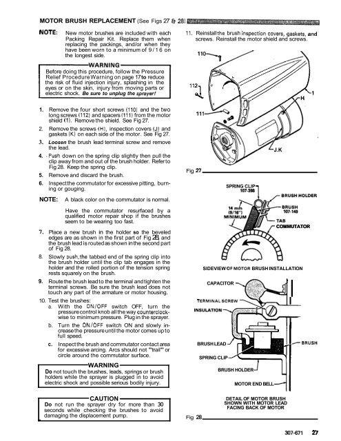
MOTOR BRUSH REPLACEMENT (See Figs 27 8 28)<br />
NOTE: New motor brushes are included with each 11. Reinstall the brush inspection covers, gaskets, and<br />
Packing Repair Kit. Replace them when<br />
replacing the packings, and/or when they<br />
screws. Reinstall the motor shield and screws.<br />
have been worn to a minimum of 9/16 on<br />
the longest side.<br />
Before doing this procedure, follow the Pressure<br />
Relief Procedure Warning on page 17 to reduce<br />
the risk of fluid injection injury, splashing in the<br />
eyes or on the skin, injury from moving parts or<br />
electric shock. Be sure to unplug the sprayer1<br />
1. Remove the four short screws (110) and the two<br />
long screws (112) and spacers (111) from the motor<br />
shield (1). Remove the shield. See Fig 27.<br />
2. Remove the screws (HI, inspection covers (JI and<br />
gaskets (K) on each side of the motor. See Fig 27.<br />
3. Loosen the brush lead terminal screw and remove<br />
the lead.<br />
4. .Push down on the spring clip slightly then pull the<br />
clip away from and out of the brush holder. Refer to<br />
Fig 28. Keep the spring clip.<br />
5. Remove and discard the brush.<br />
6. Inspect the commutator for excessive pitting, burning<br />
or gouging.<br />
NOTE:<br />
A black color on the commutator is normal.<br />
Fig n<br />
SPRING CLIP<br />
107-398<br />
J.K<br />
7.<br />
8.<br />
9.<br />
Have the commutator resurfaced by a<br />
qualified motor repair shop if the brushes<br />
seem to be wearing too fast.<br />
Place a new brush in the holder so the beveled<br />
edges are as shown in the first part of Fig 28, and<br />
the brush lead is routed as shown in the second part<br />
of Fig 28.<br />
Slowly push.the tabbed end of the spring clip into<br />
the brush holder until the clip tab engages in the<br />
holder and the rolled portion of the tension spring<br />
rests squarely on the brush.<br />
Route the brush lead to the terminal and tighten the<br />
terminal screws. Be sure the brush lead does not<br />
touch any part of the armature or motor housing.<br />
COMMUTATOR<br />
SIDEVIEW OFMOTOR BRUSH INSTALLATION<br />
CAPACITOR<br />
10. Test the brushes: TERMINALSCREW<br />
a. With the ON/OFF switch OFF, turn the<br />
pressure control knob all the way counterclockwise<br />
to minimum pressure. Plug in the sprayer.<br />
b. Turn the ON/OFF switch ON and slowly increase<br />
the pressure until the motor comes up to<br />
full speed.<br />
c. Inspect the brush and commutator contact area<br />
for excessive arcing. Arcs should not "trail" or<br />
circle around the commutator surface.<br />
WARNING<br />
Do not touch the brushes, leads, springs or brush<br />
holders while the sprayer is plugged in to avoid<br />
electric shock and possible serious bodily injury.<br />
BRUSH LEAD<br />
SPRING CLIP<br />
BRUSH HOLDER<br />
MOTOR END BELL<br />
I<br />
-BRUSH<br />
CAUTION<br />
Do not run the sprayer dry for more than 30<br />
seconds while checking the brushes to avoid<br />
damaging the displacement pump. Fig 28<br />
DETAIL OF MOTOR BRUSH<br />
SHOWN WITH MOTOR LEAD<br />
FACING BACK OF MOTOR<br />
307-671 27


