

307671D ULTRA 400 AIRLESS PAINT SPRAYER - Graco Inc.
307671D ULTRA 400 AIRLESS PAINT SPRAYER - Graco Inc.
307671D ULTRA 400 AIRLESS PAINT SPRAYER - Graco Inc.

You also want an ePaper? Increase the reach of your titles
YUMPU automatically turns print PDFs into web optimized ePapers that Google loves.
TYPE OF PROBLEM<br />
NO OUTPUT<br />
(Continued)<br />
Motor runs but pump does<br />
not stroke<br />
WHAT TO CHECK<br />
If check is OK, go to next check<br />
, Check to see if intake valve ball and<br />
piston ball are seating properly. See<br />
manual 307-793.<br />
. Check for leaking around throat packing<br />
nut which may indicate worn or damaged<br />
packings.See manual 307-793.<br />
. Check displacement pump connecting<br />
rod pin. See page 26.<br />
, Check connecting rod assembly for<br />
damage. See page 25.<br />
. Be sure crank in drive housing rotates;<br />
plug in sprayer and turn on momentarily<br />
to check. Turn off and unplug sprayer.<br />
See page 25.<br />
WHAT TO DO<br />
If check is NOT OK refer to this column<br />
,. Remove intake valve and clean. Check<br />
balls and seats for nicks; replace if<br />
necessary. See manual 307-793.<br />
#. Replace packings. See manual 307-793.<br />
Also check piston valve seat for hardened<br />
paint or nicks and replace if<br />
necessarv.<br />
. Replace pin if missing. Be sure retainer<br />
spring is fully in groove a11 around<br />
connecting rod. See page 26.<br />
!. Replace connecting rod assembly. See<br />
page 25.<br />
i. Check drive housino assemblv for<br />
damage and replac; if necessary. See<br />
page 25.<br />
EXCESSIVE PRESSURE<br />
FLUCTUATIONS<br />
Spray panern variations.<br />
. Be sure both G1 and G2 leads from<br />
bridge 1308) to circuit board 13401 are<br />
firmly connected. See page 22.<br />
'. Check stall pressure. Refer to Calibration<br />
procedure on page 24.<br />
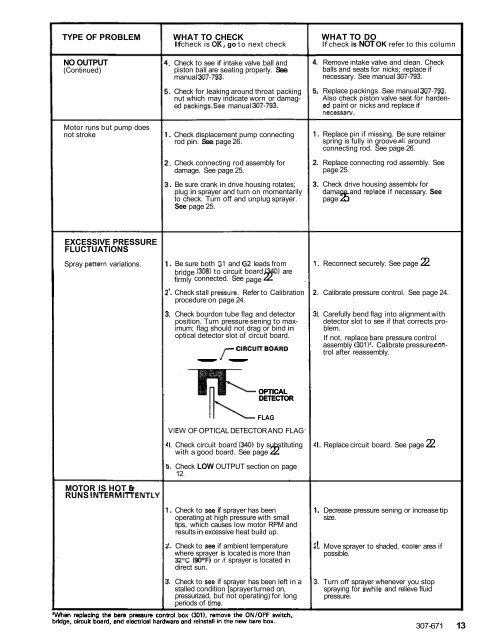
i. Check bourdon tube flag and detector<br />
position. Turn pressure sening to maximum;<br />
flag should not drag or bind in<br />
optical detector slot of circuit board.<br />
r CIRCU'TBoARD<br />
"<br />
. Reconnect securely. See page 22.<br />
I. Calibrate pressure control. See page 24.<br />
I. Carefully bend flag into alignment with<br />
detector slot to see if that corrects problem.<br />
If not, replace bare pressure control<br />
assembly (3011'. Calibrate pressure control<br />
after reassembly.<br />
OPTICAL<br />
DETECTOR<br />
MOTOR IS HOT e<br />
RUNS INTERMllTENTLY<br />
FLAG<br />
VIEW OF OPTICAL DETECTOR AND FLAG<br />
I. Check circuit board ( 3401 by substituting<br />
with a good board. See page 22.<br />
i. Check LOW OUTPUT section on page<br />
12.<br />
. Check to see if sprayer has been<br />
operating at high pressure with small<br />
tips, which causes low motor RPM and<br />
results in excessive heat build up.<br />
I. Check to see if ambient temperature<br />
where sprayer is located is more than<br />
32% (90°F) or if sprayer is located in<br />
direct sun.<br />
!. Check to see if sprayer has been left in a<br />
stalled condition [sprayer turned on,<br />
pressurized, but not operating) for long<br />
periods of time.<br />
I. Replace circuit board. See page 22.<br />
I. Decrease pressure sening or increase tip<br />
size.<br />
!. Move sprayer<br />
possible.<br />
to shaded, coolel ' area if<br />
1. Turn off sprayer whenever you stop<br />
spraying for awhile and relieve fluid<br />
pressure.<br />
307-671 13


