

307671D ULTRA 400 AIRLESS PAINT SPRAYER - Graco Inc.
307671D ULTRA 400 AIRLESS PAINT SPRAYER - Graco Inc.
307671D ULTRA 400 AIRLESS PAINT SPRAYER - Graco Inc.

Create successful ePaper yourself
Turn your PDF publications into a flip-book with our unique Google optimized e-Paper software.
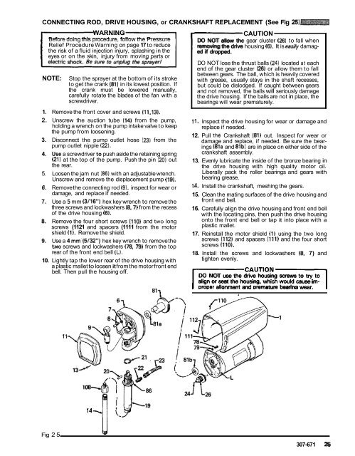
CONNECTING ROD, DRIVE HOUSING, or CRANKSHAFT<br />
r-<br />
REPLACEMENT (See Fig 25)<br />
WARNING<br />
CAUTION<br />
Before doing this procedure, follow the Pressure<br />
DO NOT allow the gear cluster (26) to fall when<br />
Relief Procedure Warning on page 17 to reduce removing the drive housing (6). It is easiiy damagthe<br />
risk of a fluid injection injury, splashing in the ed if dropped.<br />
eyes or on the skin, injury from moving parts or<br />
DO NOT lose the thrust balls (24) located at each<br />
end of the gear cluster (26) or allow them to fall<br />
between gears. The ball, which is heavily covered<br />
NOTE:<br />
with grease, usually stays in the shaft recesses,<br />
Stop the sprayer at the bottom of its stroke<br />
to get the crank (81) in its lowest position. If<br />
the crank must be lowered manually,<br />
carefully rotate the blades of the fan with a<br />
screwdriver.<br />
1. Remove the front cover and screws (11.13).<br />
2. Unscrew the suction tube (14) from the pump,<br />
holding a wrench on the pump intake valve to keep<br />
the pump from loosening.<br />
3. Disconnect the pump outlet hose (23) from the<br />
pump outlet nipple (22).<br />
4. Use a screwdriver to push aside the retaining spring<br />
(21) at the top of the pump. Push the pin (20) out<br />
the rear.<br />
5. Loosen the jam nut (86) with an adjustable wrench.<br />
Unscrew and remove the displacement pump (19).<br />
6. Remove the connecting rod (9). inspect for wear or<br />
damage, and replace if needed.<br />
7. Use a 5 mm (3/16) hex key wrench to remove the<br />
three screws and lockwashers (8.7) from the recess<br />
of the drive housing (6).<br />
8. Remove the four short screws (110) and two long<br />
screws (1121 and spacers (1111 from the motor<br />
shield (1). Remove the shield.<br />
9. Use a 4 mm.(5/32") hex key wrench to remove the<br />
two screws and lockwashers (78, 79) from the top<br />
rear of the front end bell (L).<br />
10. Lightly tap the lower rear of the drive housing with<br />
a plastic mallet to loosen it from the motor front end<br />
bell. Then pull the housing off.<br />
811<br />
but could be dislodged. If caught between gears<br />
and not removed, the balls will seriously damage<br />
the drive housing. If the balls are not in place, the<br />
bearings will wear prematurely.<br />
11. Inspect the drive housing for wear or damage and<br />
replace if needed.<br />
12. Pull the Crankshaft (81) out. Inspect for wear or<br />
damage and replace, if needed. Be sure the bearings<br />
i81a and 81b) are in place on either side of the<br />
crankshaft assembly.<br />
13. Evenly lubricate the inside of the bronze bearing in<br />
the drive housing with high quality motor oil.<br />
Liberally pack the roller bearings and gears with<br />
bearing grease.<br />
14. Install the crankshaft, meshing the gears.<br />
15. Clean the mating surfaces of the drive housing and<br />
front end bell.<br />
16. Carefully align the drive housing and front end bell<br />
with the locating pins, then push the drive housing<br />
onto the front end bell or tap it into place with a<br />
plastic mallet.<br />
17. Reinstall the motor shield (1) using the two long<br />
screws (112) and spacers (111) and the four short<br />
screws (110).<br />
18. Install the screws and lockwashers (8, 7) and<br />
tighten evenly.<br />
DO NOT use the drive housing screws to try to<br />
align or seat the housing, which would cause im-<br />
I DroDer C alionment A Uand Dremature T I bearina O wear. N 1<br />
.. w<br />
I<br />
86<br />
24<br />
Fig 25<br />
307-671 25


