XPM 200HR™ v1 - Hengstler GmbH
XPM 200HR™ v1 - Hengstler GmbH
XPM 200HR™ v1 - Hengstler GmbH

You also want an ePaper? Increase the reach of your titles
YUMPU automatically turns print PDFs into web optimized ePapers that Google loves.
<strong>XPM</strong> 200HR Thermal Printer Family HENGSTLER ®<br />
6. Installation<br />
6.1. Function<br />
Please note that the <strong>XPM</strong> 200HR printer is a module designed to be integrated into a<br />
system and to be operated only as a part of that system, for example, in a kiosk. All technical<br />
specifications and instructions contained in this manual and related documentation must be<br />
considered and complied with in order to achieve successful operation in the completed<br />
system.<br />
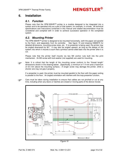
6.2. Mounting Printer<br />
The <strong>XPM</strong> 200HR printer is designed to be mounted horizontally, (with the paper exit parallel<br />
to the floor), and separately from its controller. See figure 10 and drawing D690075 for<br />
detailed dimensions, mounting screw sizes, etc. If no presenter is being used, the printer may<br />
be angled downward by 90°. It may also be angled upward, as long as the design of the<br />
system into which it mounts is such that a printout cannot slide back into the printer after it is<br />
cut.<br />
<br />
<br />
Please note that the printer itself mounts via two M4 anchor nuts built into the print<br />
mechanism. An M3 screw with lock washer (not supplied) are used for mounting.<br />
Note: It is critical that the length of the mounting screw conform to the “thread length”<br />
dimensions shown in the drawing below. (Specifically, a minimum of 7.4 mm and a maximum<br />
of 8.5 mm above the mounting surface.) A longer screw may damage the printer, while a<br />
shorter one may not grip it properly.<br />
If a presenter is used, the printer must be mounted parallel to the floor with the paper exiting<br />
to parallel to the floor. An angled orientation will interfere with the loop presenter function.<br />
Care must be taken during installation to ensure that cables are not pinched or cut at any<br />
time, including when any doors or hatches are closed or moving parts of the device moved.<br />
Figure 10<br />
Part No. D 690 074 Mod. No. 4 300113 LEV page 19 of 32