Fan-in WLCSP matures, what's next? IMT on the role ... - I-Micronews
Fan-in WLCSP matures, what's next? IMT on the role ... - I-Micronews
Fan-in WLCSP matures, what's next? IMT on the role ... - I-Micronews

You also want an ePaper? Increase the reach of your titles
YUMPU automatically turns print PDFs into web optimized ePapers that Google loves.
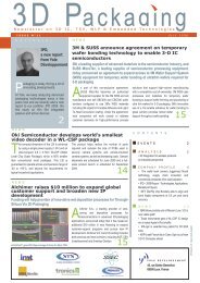
F E B R U A R Y 2 0 1 0 i s s u e n ° 1 4<br />
N e w s l e t t e r o n 3 D I C , T S V , W L P & E m b e d d e d T e c h n o l o g i e s<br />
Reliability<br />
The reliability simulati<strong>on</strong>s were d<strong>on</strong>e compar<str<strong>on</strong>g>in</str<strong>on</strong>g>g<br />
<strong>the</strong> copper post <strong>on</strong> chip and µPILR <str<strong>on</strong>g>in</str<strong>on</strong>g>terc<strong>on</strong>nects<br />
under two test c<strong>on</strong>diti<strong>on</strong>s, -55 to 125 0C (<strong>the</strong>rmal<br />
shock) and 0 to 100 °C (<strong>the</strong>rmal cycl<str<strong>on</strong>g>in</str<strong>on</strong>g>g). The<br />
µPILR <str<strong>on</strong>g>in</str<strong>on</strong>g>terc<strong>on</strong>nect is expected to pass <strong>the</strong><br />
reliability tests and is approximately 20% better<br />
<str<strong>on</strong>g>in</str<strong>on</strong>g> fatigue life, which is primarily due to <strong>the</strong> extra<br />
amount of solder. Reliability test<str<strong>on</strong>g>in</str<strong>on</strong>g>g was also d<strong>on</strong>e<br />
and no failures were observed after 1000 cycles<br />
under -55 to 125 °C <strong>the</strong>rmal shock test c<strong>on</strong>diti<strong>on</strong>s.<br />
C<strong>on</strong>clusi<strong>on</strong>s<br />
The substrates underwent c<strong>on</strong>venti<strong>on</strong>al hot oil<br />
tests (20-260 °C, 50 cycles) successfully. Bump<br />
shear tests were d<strong>on</strong>e before and after age<str<strong>on</strong>g>in</str<strong>on</strong>g>g (150<br />
°C, 1000 hours) and <strong>the</strong> shear force was <str<strong>on</strong>g>in</str<strong>on</strong>g> 40-60<br />
gm range, well above <strong>the</strong> required 35 gm force.<br />
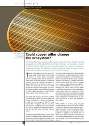
Test vehicle design and assembly<br />
The test vehicle was designed to represent a high<br />
comput<str<strong>on</strong>g>in</str<strong>on</strong>g>g applicati<strong>on</strong>. The chip measured 20 mm<br />
x 18 mm x 0.75 mm with 10,132 <str<strong>on</strong>g>in</str<strong>on</strong>g>terc<strong>on</strong>nects at<br />
0.15 mm (signal) and 0.2 mm (power/ground) pitch.<br />
The substrate measured 40 mm x 40 mm x 1.2<br />
mm and had 10 metal layers <str<strong>on</strong>g>in</str<strong>on</strong>g> a 3-4-3 build-up <strong>on</strong><br />
core stack. The <str<strong>on</strong>g>in</str<strong>on</strong>g>terc<strong>on</strong>nect details al<strong>on</strong>g with <strong>the</strong><br />
package cross-secti<strong>on</strong> are given <str<strong>on</strong>g>in</str<strong>on</strong>g> Figure 2.<br />
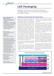
The package assembly was d<strong>on</strong>e us<str<strong>on</strong>g>in</str<strong>on</strong>g>g<br />
c<strong>on</strong>venti<strong>on</strong>al flip-chip equipment and processes.<br />
After process optimizati<strong>on</strong>, both flip-chip reflow<br />
and underfill processes were close to 100% yield.<br />
Figure 3 shows <strong>the</strong> package assembly results.<br />
After <strong>the</strong> underfill process, <strong>the</strong> heat spreader was<br />
attached with Indium as <strong>the</strong> <strong>the</strong>rmal <str<strong>on</strong>g>in</str<strong>on</strong>g>terface<br />
material (TIM), accord<str<strong>on</strong>g>in</str<strong>on</strong>g>g to <strong>the</strong> design as shown<br />
<str<strong>on</strong>g>in</str<strong>on</strong>g> Figure 2.<br />
Figure 2: Test vehicle design for reliability and electromigrati<strong>on</strong> test<str<strong>on</strong>g>in</str<strong>on</strong>g>g<br />
Electromigrati<strong>on</strong> performance<br />
For high performance comput<str<strong>on</strong>g>in</str<strong>on</strong>g>g, two ma<str<strong>on</strong>g>in</str<strong>on</strong>g><br />
requirements are electromigrati<strong>on</strong> performance<br />
and reliability. The electromigrati<strong>on</strong> test<str<strong>on</strong>g>in</str<strong>on</strong>g>g<br />
was d<strong>on</strong>e under two different c<strong>on</strong>diti<strong>on</strong>s. The<br />
samples passed 1300 hours without failure under<br />
accelerated test c<strong>on</strong>diti<strong>on</strong>s of 30.0kA/cm2 (1.0A)<br />
& 160°C and passed 1000 hours without failure<br />
under highly accelerated test c<strong>on</strong>diti<strong>on</strong>s of 45.0kA/<br />
cm2 (1.5A) & 160°C. The resistance was m<strong>on</strong>itored<br />
c<strong>on</strong>t<str<strong>on</strong>g>in</str<strong>on</strong>g>uously and <strong>the</strong> rise <str<strong>on</strong>g>in</str<strong>on</strong>g> resistance was less<br />
than 3%. There are no voids <strong>on</strong> <strong>the</strong> substrate side<br />
and void formati<strong>on</strong> can be seen <strong>on</strong> <strong>the</strong> chip side.<br />
Compared to published results for high-lead<br />
bump, lead-free bump and copper post <strong>on</strong> chip,<br />
<strong>the</strong>se results are <strong>the</strong> best when <strong>the</strong> accelerati<strong>on</strong><br />
factors are taken <str<strong>on</strong>g>in</str<strong>on</strong>g>to account. It is estimated<br />
that <strong>the</strong> accelerati<strong>on</strong> factor is approximately 2.5x<br />
from 15.0kA/cm2 to 45.0kA/cm2, and about 2x<br />
from 125 °C to 160 °C for a total of 5x for 45.0kA/<br />
cm2 & 160°C compared to 15.0kA/cm2 & 115°C<br />
test c<strong>on</strong>diti<strong>on</strong>s. This implies that 1000 hours of<br />
successful test<str<strong>on</strong>g>in</str<strong>on</strong>g>g under 45.0kA/cm2 & 160°C<br />
corresp<strong>on</strong>ds to about 5000 hours under 15.0kA/<br />
cm2 & 115°C, which is better than <strong>the</strong> results<br />
published <str<strong>on</strong>g>in</str<strong>on</strong>g> for copper posts <strong>on</strong> chip.<br />
The packag<str<strong>on</strong>g>in</str<strong>on</strong>g>g performance has to keep improv<str<strong>on</strong>g>in</str<strong>on</strong>g>g<br />
to meet <strong>the</strong> ITRS roadmaps and to m<str<strong>on</strong>g>in</str<strong>on</strong>g>imize<br />
negatively impact<str<strong>on</strong>g>in</str<strong>on</strong>g>g <strong>the</strong> performance of <strong>the</strong> chip<br />
and <strong>the</strong> system. The flip-chip <str<strong>on</strong>g>in</str<strong>on</strong>g>terc<strong>on</strong>nects are<br />
<strong>the</strong> key enablers for better package performance<br />
through improvements <str<strong>on</strong>g>in</str<strong>on</strong>g> f<str<strong>on</strong>g>in</str<strong>on</strong>g>e-pitch, current<br />
carry<str<strong>on</strong>g>in</str<strong>on</strong>g>g capacity and reliability. High-lead<br />
bumps are be<str<strong>on</strong>g>in</str<strong>on</strong>g>g phased out and lead-free<br />
bumps have limitati<strong>on</strong>s regard<str<strong>on</strong>g>in</str<strong>on</strong>g>g f<str<strong>on</strong>g>in</str<strong>on</strong>g>e-pitch and<br />
electromigrati<strong>on</strong> performance. Copper post <strong>on</strong><br />
chip and µPILR <strong>on</strong> substrate are two <str<strong>on</strong>g>in</str<strong>on</strong>g>terc<strong>on</strong>nect<br />
technologies that meet <strong>the</strong> future packag<str<strong>on</strong>g>in</str<strong>on</strong>g>g<br />
requirements, with µPILR expected to perform<br />
better <str<strong>on</strong>g>in</str<strong>on</strong>g> reliability. The reliability benefit gets<br />
more pr<strong>on</strong>ounced with <strong>the</strong> transiti<strong>on</strong> from low-k to<br />
extreme low-k dielectrics <strong>on</strong> <strong>the</strong> chip side. More<br />
research work is <strong>on</strong>go<str<strong>on</strong>g>in</str<strong>on</strong>g>g with µPILR <str<strong>on</strong>g>in</str<strong>on</strong>g>terc<strong>on</strong>nects<br />
and more research <str<strong>on</strong>g>in</str<strong>on</strong>g> general is needed by <strong>the</strong><br />
<str<strong>on</strong>g>in</str<strong>on</strong>g>dustry to ensure that <strong>the</strong> packag<str<strong>on</strong>g>in</str<strong>on</strong>g>g for high<br />
performance comput<str<strong>on</strong>g>in</str<strong>on</strong>g>g facilitates excellent<br />
electrical and <strong>the</strong>rmal performance while meet<str<strong>on</strong>g>in</str<strong>on</strong>g>g<br />
reliability and cost requirements.<br />
Ilyas Mohammed<br />
Tessera Inc.<br />
3025 Orchard Parkway, San Jose CA 95134<br />
www.tessera.com<br />
Ilyas Mohammed<br />
Figure 3: Package assembly results us<str<strong>on</strong>g>in</str<strong>on</strong>g>g c<strong>on</strong>venti<strong>on</strong>al flip-chip reflow and underfill processes yielded near 100%<br />
with well-aligned jo<str<strong>on</strong>g>in</str<strong>on</strong>g>ts and void-free underfill<br />
Ilyas Mohammed is director, package development<br />
Micro-electr<strong>on</strong>ics, at Tessera Technologies <str<strong>on</strong>g>in</str<strong>on</strong>g> San<br />
Jose, Calif. Prior to this positi<strong>on</strong>, Mohammed<br />
served as senior manager, Design and Simulati<strong>on</strong>,<br />
and lead eng<str<strong>on</strong>g>in</str<strong>on</strong>g>eer<str<strong>on</strong>g>in</str<strong>on</strong>g>g, Micro-electr<strong>on</strong>ics Products,<br />
at Tessera. He is a post doctoral fellow at The<br />
University of Texas at Aust<str<strong>on</strong>g>in</str<strong>on</strong>g>, and holds degrees<br />
from Iowa State University <str<strong>on</strong>g>in</str<strong>on</strong>g> Ames, Iowa, and <strong>the</strong><br />
Indian Institute of Technology <str<strong>on</strong>g>in</str<strong>on</strong>g> Madras, India.<br />
11