Reduction of Noise Emission of Suboptimal Operating ... - IAG
Reduction of Noise Emission of Suboptimal Operating ... - IAG
Reduction of Noise Emission of Suboptimal Operating ... - IAG

Create successful ePaper yourself
Turn your PDF publications into a flip-book with our unique Google optimized e-Paper software.
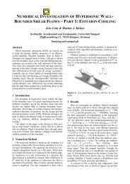
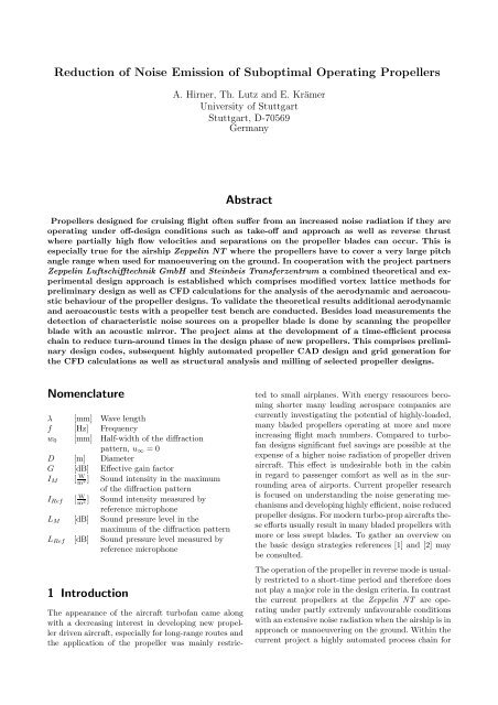
<strong>Reduction</strong> <strong>of</strong> <strong>Noise</strong> <strong>Emission</strong> <strong>of</strong> <strong>Suboptimal</strong> <strong>Operating</strong> Propellers<br />
A. Hirner, Th. Lutz and E. Krämer<br />
University <strong>of</strong> Stuttgart<br />
Stuttgart, D-70569<br />
Germany<br />
Abstract<br />
Propellers designed for cruising flight <strong>of</strong>ten suffer from an increased noise radiation if they are<br />
operating under <strong>of</strong>f-design conditions such as take-<strong>of</strong>f and approach as well as reverse thrust<br />
where partially high flow velocities and separations on the propeller blades can occur. This is<br />
especially true for the airship Zeppelin NT where the propellers have to cover a very large pitch<br />
angle range when used for manoeuvering on the ground. In cooperation with the project partners<br />
Zeppelin Luftschifftechnik GmbH and Steinbeis Transferzentrum a combined theoretical and experimental<br />
design approach is established which comprises modified vortex lattice methods for<br />
preliminary design as well as CFD calculations for the analysis <strong>of</strong> the aerodynamic and aeroacoustic<br />
behaviour <strong>of</strong> the propeller designs. To validate the theoretical results additional aerodynamic<br />
and aeroacoustic tests with a propeller test bench are conducted. Besides load measurements the<br />
detection <strong>of</strong> characteristic noise sources on a propeller blade is done by scanning the propeller<br />
blade with an acoustic mirror. The project aims at the development <strong>of</strong> a time-efficient process<br />
chain to reduce turn-around times in the design phase <strong>of</strong> new propellers. This comprises preliminary<br />
design codes, subsequent highly automated propeller CAD design and grid generation for<br />
the CFD calculations as well as structural analysis and milling <strong>of</strong> selected propeller designs.<br />
Nomenclature<br />
λ [mm] Wave length<br />
f [Hz] Frequency<br />
w 0<br />
[mm] Half-width <strong>of</strong> the diffraction<br />
pattern, u ∞ = 0<br />
D [m] Diameter<br />
G [dB] Effective gain factor<br />
I M [ W m<br />
] Sound intensity in the maximum<br />
2<br />
<strong>of</strong> the diffraction pattern<br />
I Ref [ W m<br />
] Sound intensity measured by<br />
2<br />
reference microphone<br />
L M [dB] Sound pressure level in the<br />
maximum <strong>of</strong> the diffraction pattern<br />
L Ref [dB] Sound pressure level measured by<br />
reference microphone<br />
1 Introduction<br />
The appearance <strong>of</strong> the aircraft turb<strong>of</strong>an came along<br />
with a decreasing interest in developing new propeller<br />
driven aircraft, especially for long-range routes and<br />
the application <strong>of</strong> the propeller was mainly restricted<br />
to small airplanes. With energy ressources becoming<br />
shorter many leading aerospace companies are<br />
currently investigating the potential <strong>of</strong> highly-loaded,<br />
many bladed propellers operating at more and more<br />
increasing flight mach numbers. Compared to turb<strong>of</strong>an<br />
designs significant fuel savings are possible at the<br />
expense <strong>of</strong> a higher noise radiation <strong>of</strong> propeller driven<br />
aircraft. This effect is undesirable both in the cabin<br />
in regard to passenger comfort as well as in the surrounding<br />
area <strong>of</strong> airports. Current propeller research<br />
is focused on understanding the noise generating mechanisms<br />
and developing highly efficient, noise reduced<br />
propeller designs. For modern turbo-prop aircrafts these<br />
efforts usually result in many bladed propellers with<br />
more or less swept blades. To gather an overview on<br />
the basic design strategies references [1] and [2] may<br />
be consulted.<br />
The operation <strong>of</strong> the propeller in reverse mode is usually<br />
restricted to a short-time period and therefore does<br />
not play a major role in the design criteria. In contrast<br />
the current propellers at the Zeppelin NT are operating<br />
under partly extremly unfavourable conditions<br />
with an extensive noise radiation when the airship is in<br />
approach or manoeuvering on the ground. Within the<br />
current project a highly automated process chain for
time-efficient design <strong>of</strong> noise reduced propellers is developed<br />
which aims at the design <strong>of</strong> a new stern thruster<br />
for the Zeppelin NT under particular consideration<br />
<strong>of</strong> <strong>of</strong>f-design conditions. To get new insights in the<br />
noise generating mechanisms <strong>of</strong> the current 3-bladed<br />
propeller both numerical and experimental studies are<br />
conducted with the full-sale and a model propeller. In<br />
addition a second propeller with a flexible mounting <strong>of</strong><br />
the blades at the hub is examined. This configuration<br />
is said to have noise reducing effects as the blades can<br />
oscillate to a certain amount if the blade encounters<br />
unsteady inflow caused by atmospheric turbulence or<br />
inclined inflow. This effect will be studied by operating<br />
the propeller in inclined flight condition both with flexible<br />
and fixed mounting <strong>of</strong> the blades.<br />
2 Process chain for highly<br />
automated propeller design<br />
As for commercial aircraft there is a large need in increasing<br />
efficiency as well as reducing noise emission<br />
<strong>of</strong> propeller driven general aviation aircraft. This effort<br />
arises due to a lower noise acceptance <strong>of</strong> the population<br />
resulting in stricter noise regulations <strong>of</strong> local<br />
airfields. The current state <strong>of</strong> the art propeller design<br />
<strong>of</strong> small propeller manufacturers is usually limited to<br />
preliminary design methods and broadly based on experience.<br />
This approach cannot fully account for the<br />
complex three dimensional flow field about a propeller.<br />
Therefore within the current project detailed numerical<br />
studies combined with experimental work are<br />
conducted to develop new design criteria for noise reduced,<br />
efficient propellers with special attention to <strong>of</strong>fdesign<br />
conditions. To ensure short turn-around times<br />
<strong>of</strong> a propeller design there is a need for a highly automated<br />
process chain comprising both numerical as<br />
well as experimental studies. In the future parts <strong>of</strong> this<br />
process chain can be supplied to local propeller manufacturers<br />
as service work. The components <strong>of</strong> this<br />
procedure according to Figure 1 will be presented in<br />
the following.<br />
Preliminary Design<br />
XROTOR<br />
CAD, Structural Analysis<br />
CATIA<br />
Experiment<br />
Thrust, Torque, Visualisation,<br />
Acoustics<br />
New <strong>Noise</strong><br />
Reduced Design<br />
Evaluation <strong>of</strong> Design<br />
Numerical Flow Simulations<br />
FLOWer / TAU<br />
2.1 Preliminary design<br />
For preliminary design studies the propeller code<br />
XROTOR from Drela [3] is used. This code allows<br />
the interactive design and analysis <strong>of</strong> free-tip as well<br />
as ducted propellers. The propeller blade is represented<br />
by the classical lifting-line theory whereas the aerodynamic<br />
characteristics <strong>of</strong> the blade sections can<br />
be modelled by specifying arbitrary airfoil aerodynamic<br />
properties. To account for compressibility effects<br />
a Prandtl-Glauert correction is applied. The induced<br />
velocities are calculated by numerically solving for the<br />
exact potential flowfield about the helical vortex field.<br />
This approach is therefore valid for all advance ratios<br />
and blade numbers compared to classical theories<br />
which assume a small advance ratio and many blades.<br />
A first-order correction for the change in the pitch <strong>of</strong><br />
the trailing sheets is applied to account for the propeller’s<br />
self-induction which is important for highlyloaded<br />
propellers. To examine more general propeller<br />
geometries with non-radial lifting lines (raked or swept<br />
blades) an additional discrete vortex wake formulation<br />
is implemented to calculate the induced velocities.<br />
Discrete line vortices on the rigid helicoidal wake<br />
surface trailing from the lifting line into the farfield<br />
downstream are used to calculate the velocitiy on the<br />
propeller lifting line. <strong>Noise</strong> level contour plots can be<br />
calculated on a rectangular grid based on a method<br />
developped by Succi [4],[5].<br />
This code is used for time-efficient investigation <strong>of</strong> the<br />
aerodynamic and aeroacoustic behaviour <strong>of</strong> different<br />
blade geometries both under design and <strong>of</strong>f-design conditions.<br />
This approach delivers important information<br />
concerning necessary lift coefficients <strong>of</strong> the airfoils<br />
as well as Reynolds- and Mach number distribution<br />
along the blade at an early stage in the design process.<br />
The rotation <strong>of</strong> the propeller blades and the resulting<br />
centrifugal and Coriolis effects strongly influence the<br />
boundary layer development on the blade especially<br />
near the hub. Due to these effects unstalled flow can<br />
be achieved at very high angle <strong>of</strong> attack and stall itself<br />
occurs more gently. To account for these effects numerous<br />
approaches were derived in literature which either<br />
consider rotational effects by correcting calculated 2Dairfoil<br />
polars [6], [7] or directly implement a modified<br />
boundary layer model into the airfoil code [8].<br />
Most <strong>of</strong> these 2D-corrections were derived for slow turning<br />
wind turbines. Within the current project rotational<br />
effects on the airfoil characteristics will be considered<br />
by evaluating both CFD and experimental data<br />
gathered with a propeller test bench (see Figure8).<br />
Grid Generation<br />
GRIDGEN<br />
Figure 1: Flowchart <strong>of</strong> process chain<br />
2.2 CAD design and structural analysis<br />
The propeller geometry output from the XROTOR code<br />
is imported by the 3D-CAD-CAM s<strong>of</strong>tware package<br />
CATIA by means <strong>of</strong> a macro. This procedure ensu-
es a time-efficient generation <strong>of</strong> a watertight propeller<br />
surface which can be used as a basis for further<br />
grid generation. As the subsequent grid generation for<br />
the numerical flow simulations is script based as well,<br />
it’s advantageous when each propeller geometry has<br />
the same layout to be uniquely identified by the mesh<br />
generating s<strong>of</strong>tware independent <strong>of</strong> the detailed blade<br />
geometry. The propeller surface is exported in IGESformat<br />
which is the basis for mesh generation as well<br />
as for milling the moulds <strong>of</strong> selected propeller designs<br />
for further experimental studies. In addition CATIA is<br />
used for the structural analysis <strong>of</strong> the propeller blades,<br />
propeller shaft and clamping hub.<br />
2.3 Grid generation<br />
The computational mesh for the numerical flow simulations<br />
is based on the IGES surface data <strong>of</strong> the propeller<br />
blades and generated with the meshing s<strong>of</strong>tware<br />
GRIDGEN from POINTWISE [9]. For time-efficient<br />
grid generation <strong>of</strong> multiple different blade geometries<br />
and blade numbers this procedure was realised within<br />
a script based approach. For first preliminary numerical<br />
studies including interference effects <strong>of</strong> the propeller<br />
blades with a motor cowling an unstructered<br />
approach was realised first. In addition, a completely<br />
structered procedure is persecuted. As no wall function<br />
is applied in the CFD calculations a y + -value <strong>of</strong><br />
about 1 is anticipated for the first cell layer. In the<br />
grid 30 cell layers are extruded from the blade surface<br />
to represent the boundary layer on the blades. In addition<br />
the cell distribution on the propeller blades and<br />
the farfield and its extent are easily adaptable within<br />
the script. This procedure is necessary as the numerical<br />
flow simulations are the basis for the calculation<br />
<strong>of</strong> noise levels both in the vicinity <strong>of</strong> the blade as well<br />
as in the near farfield by evaluating the pressure fluctuations.<br />
As no special CAA method is used it must<br />
be granted that no erroneous sound levels result due<br />
to inappropriate discretization <strong>of</strong> the farfield.<br />
2.4 Numerical flow simulations<br />
The numerical flow simulations are conducted with the<br />
flow solvers TAU [10] and FLOWer, both developed by<br />
the DLR.<br />
TAU is a three-dimensional, parallel, hybrid, multigrid<br />
code. It implements a finite volume scheme for solving<br />
the Reynolds-averaged Navier-Stokes (RANS) equations.<br />
The code uses explicit time stepping, the multistep<br />
Runge-Kutta scheme and optionally an implicit<br />
time stepping with a LU-time scheme. For accelerating<br />
the convergence to steady state a local time-stepping<br />
concept, different residual smoothing algorithms and<br />
a geometrical multigrid method are implemented.<br />
At the beginning the main focus <strong>of</strong> the project is to<br />
examine different propeller configurations in regard to<br />
noise emission and aerodynamic behaviour. In combination<br />
with the preliminary studies with XROTOR<br />
these numerical flow simulations <strong>of</strong>fer detailed output<br />
for the selection or design <strong>of</strong> adapted propeller airfoil<br />
sections operating without separation under <strong>of</strong>fdesign<br />
conditions <strong>of</strong> the propeller. At this stage propeller<br />
operation is restricted to axial inflow. Therefore<br />
time-consuming unsteady calculations and the application<br />
<strong>of</strong> the chimera technique are not necessary as a<br />
quasi-steady approach is adequate. To consider interference<br />
effects the cowling is modelled as an axisymmetric<br />
body. To prevent a rotating boundary layer on<br />
the cowling EULER boundary conditions are applied<br />
to this surface whereas the propeller blades are calculated<br />
fully viscous.<br />
2.5 Experimental investigations<br />
The design loop is closed by experimental studies conducted<br />
with a propeller test bench where selected propeller<br />
designs can be further tested. This facility <strong>of</strong>fers<br />
the possibility to thoroughly investigate the predicted<br />
performance from the previous flow simulations<br />
and serves simultaneously to validate the used codes.<br />
This is especially important as the project is aimed<br />
at the reduction <strong>of</strong> noise under <strong>of</strong>f-design conditions<br />
when partially high flow velocities and flow separation<br />
on the propeller blades have to be expected.<br />
Propeller test bench<br />
The propeller test bench was constructed and built by<br />
Steinbeis-Transferzentrum [11]. The propeller is driven<br />
by a compact air-cooled servo motor. Propeller thrust<br />
is measured with a load cell mounted in-between the<br />
rear side <strong>of</strong> the motor and a rib in the motor cowling.<br />
The motor is mounted rotatable about its length axis<br />
so that propeller torque can be measured with a second<br />
lateral mounted load cell (Figure 2). With an additional<br />
turnable rig two prandtl sensors can be positioned<br />
near the propeller plane, one sensor being positioned<br />
ahead and the second one behind the propeller plane.<br />
Evaluation <strong>of</strong> the static and dynamic pressure at these<br />
two locations enables the determination <strong>of</strong> ciculation<br />
at a specific radial position on the blade and therefore<br />
<strong>of</strong>fers additional information on possible separation in<br />
addition to paint coatings. Within the current project<br />
the propeller diameters to be examined are about 1m<br />
und the rotational speed about 3250U/min. This rotational<br />
speed at the test bench results from the chosen<br />
scale factor between the current reference propeller <strong>of</strong><br />
the Zeppelin NT and the model propeller to guarantee<br />
the same blade tip mach number <strong>of</strong> 0.5 between original<br />
and model propeller which is essential to conserve<br />
aeroacoustic similarity. Reynolds number effects between<br />
both propeller scales can be determined by inve-
stigating the original propeller at a second test bench<br />
with identical propulsion units from the Zeppelin NT.<br />
velocities <strong>of</strong> about 7 m/s at the outside location <strong>of</strong> the<br />
test bench.<br />
Acoustic measurements<br />
Figure 2: Propeller test bench for model propellers<br />
Test facility Gust Wind Tunnel<br />
The experimental studies are conducted at the Gust<br />
Wind Tunnel <strong>of</strong> the institute. This wind tunnel was<br />
concipated to simulate gusts on wind turbines by suddenly<br />
opening and closing sails at the inlet <strong>of</strong> the tunnel.<br />
The tunnel itself has a diameter <strong>of</strong> 6.3m and the<br />
length <strong>of</strong> the test section is about 8m with a maximum<br />
flow velocity <strong>of</strong> 18m/s which corresponds to the effective<br />
inflow velocity at the stern propeller <strong>of</strong> the Zeppelin<br />
NT. For acoustic measurements the test bench is<br />
operated outside the test section to avoid disturbances<br />
from the tunnel walls. For the Zeppelin NT noise levels<br />
are highest when the airship is manoeuvering on the<br />
ground and the propeller operates under nearly static<br />
thrust conditions. The inflow area <strong>of</strong> the wind tunnel<br />
was extended with a mobile frame construction with<br />
nets <strong>of</strong> varying porosity fastened between the spars<br />
(see Figure 8). Because <strong>of</strong> the missing contraction <strong>of</strong><br />
the wind tunnel itself this construction guarantees a<br />
more laminar and steady flow in the test section and<br />
the sensitivity <strong>of</strong> the tunnel concerning atmospheric<br />
turbulence is reduced. On the other hand, the canalization<br />
<strong>of</strong> the flow due to this device still <strong>of</strong>fers flow<br />
Acoustic noise level contour maps dependent on flow<br />
veloctity and blade angle <strong>of</strong> the propeller will be captured<br />
by ground microphones. This approach delivers<br />
the total sound pressure level at a specific location but<br />
<strong>of</strong>fers no indication <strong>of</strong> the noise source distribution on<br />
the blades. To clarify sound generating mechanisms<br />
and to localize the dominating noise sources along a<br />
propeller blade especially under <strong>of</strong>f-design conditions<br />
an acoustic mirror with elliptical shape was designed<br />
which serves as a highly directional microphone system.<br />
The characteristic <strong>of</strong> an elliptic mirror is to focus<br />
sound waves emanating from a volume element<br />
<strong>of</strong> a source distribution at the far focus upon the near<br />
focus point where a microphone is located. Due to<br />
constructive superposition <strong>of</strong> sound waves at the microphone<br />
a gain is achievable dependent on the shape<br />
<strong>of</strong> the mirror. Provided that there is no significant flow<br />
between sound source and mirror both spatial resolution<br />
and gain factor <strong>of</strong> the mirror system are mainly<br />
limited by diffraction <strong>of</strong> the sound waves at the edge<br />
<strong>of</strong> the mirror.<br />
As mentioned before the acoustic measurements will<br />
be conducted outside the test section <strong>of</strong> the wind tunnel.<br />
In this case the test bench is mounted on an additional<br />
framework to keep the propeller axis centered<br />
in the tunnel axis. The acoustic mirror is positioned<br />
ahead or behind the propeller and can be moved parallel<br />
to the propeller rotating plane with a linear drive<br />
unit. The focus point is adjusted scarcely above the<br />
blade surface <strong>of</strong> a horizontally levelled blade. By moving<br />
the mirror parallel to the propeller plane from one<br />
blade tip to the other, the noise distribution <strong>of</strong> sources<br />
emanating from the vicinity <strong>of</strong> the blade surface can be<br />
captured. By positioning the mirror ahead or behind<br />
the propeller noise sources emanating rather from the<br />
upper or lower side can be detected (Figure 3). As the<br />
distance <strong>of</strong> the focus point to the blade surface slightly<br />
varies dependent on blade angle and airfoil thickness<br />
distribution it has to be studied if a significant difference<br />
between both positions can be detected at all.<br />
In the design <strong>of</strong> the mirror some geometric restrictions<br />
were given by the dimensions <strong>of</strong> the wind tunnel. The<br />
diameter <strong>of</strong> the mirror should be kept small enough<br />
to avoid any blocking effects on the propeller flow but<br />
large enough to capture low frequencies in the range<br />
<strong>of</strong> the blade passing frequency. The focal length <strong>of</strong> the<br />
mirror is influenced by the desire <strong>of</strong> positioning the<br />
mirror both in front and behind the propeller plane in<br />
the inflow section <strong>of</strong> the tunnel (Figure 3).
Figure 3: Alignment <strong>of</strong> acoustic mirror<br />
Theoretical relations were derived both for the gain<br />
and the spatial resolution <strong>of</strong> an acoustic mirror by<br />
Grosche [12]. The effective gain factor G according to<br />
equation (1) describes the enhancement <strong>of</strong> the sound<br />
intensity caused by the focusing effect <strong>of</strong> the elliptic<br />
mirror at the mirror microphone compared to its free<br />
field value measured by a reference microphone at the<br />
same distance from the sound source. The ability <strong>of</strong> the<br />
acoustic mirror to enhance sound intensities at the far<br />
focus and therefore discriminate background noise makes<br />
this system a highly directional sound microphone<br />
system with the ability to resolve sound sources in all<br />
directions normal to the mirror axis.<br />
( )<br />
IM<br />
G = L M − L Ref = 10 log<br />
I Ref<br />
)<br />
(1)<br />
= 10 log<br />
(0.5 D4<br />
λ 2 B 2<br />
Whereas the focusing effect decreases relatively slowly<br />
in the direction <strong>of</strong> the mirror axis the maximum<br />
in vertical and lateral direction is much more sharper.<br />
Using the theory <strong>of</strong> diffraction <strong>of</strong> waves by a circular<br />
aperture provides an approximate relation for the halfwidth<br />
w 0 <strong>of</strong> the diffraction pattern <strong>of</strong> a point source.<br />
According to Figure 4 w 0 is the distance from the maximum<br />
within which the sound intensity decreases by<br />
50%.<br />
(2) w 0 = 0.54λ S D<br />
In consideration <strong>of</strong> all parameters the final diameter<br />
D <strong>of</strong> the acoustic mirror was set to 2.45m and the<br />
focal length S to 4.5m with the distance <strong>of</strong> the near<br />
focus B chosen to 1.06m.<br />
The calibration <strong>of</strong> the acoustic mirror was performed<br />
using a Kenwood KA 3080 R preamplifier and a broadband<br />
loudspeaker vifa 10 BGS 119/8 which provides a<br />
balanced frequency response. Both for the mirror and<br />
reference microphone 1/2” Free-field Microphone Type<br />
4190 from Brüel & Kjæer were used. For lack <strong>of</strong><br />
Figure 4: Principle <strong>of</strong> acoustic mirror [12]<br />
a special acoustic room various problems due to reflections<br />
and diffraction emerged during the beginning<br />
<strong>of</strong> the calibration process. For this reason the principle<br />
<strong>of</strong> the impulse response measurement <strong>of</strong> the s<strong>of</strong>tware<br />
package ARTA [13] was utilized to generate a<br />
swept sine impulse <strong>of</strong> about 5 ms short enough to avoid<br />
ground reflections at the microphones. The corresponding<br />
ARTA measurement setup for single channel<br />
measurement setup is shown in Figure 5. Due to the<br />
single channel setup the response <strong>of</strong> mirror and reference<br />
microphone were not measured simultaneously<br />
but in two subsequent measurements.<br />
Figure 5: Single channel measurement setup for acoustical<br />
measurements with ARTA s<strong>of</strong>tware<br />
[13]<br />
The resulting gain factor <strong>of</strong> the elliptical mirror is<br />
shown in Figure 6 and the spatial resolution in Figure<br />
7. The effective gain factor shows a good agreement<br />
compared to the theoretical relation according to eq.<br />
(1) derived by Grosche [12]. In the relevant frequency<br />
range a gain <strong>of</strong> about 10 to 40dB is attainable.<br />
Above frequencies <strong>of</strong> about 10kHz a decrease in the<br />
measured gain factor <strong>of</strong> the mirror can be detected<br />
which is caused by the non-omnidirectional directivity<br />
<strong>of</strong> the loudspeaker. These effects have to be corrected
y measuring the directivity pattern <strong>of</strong> the loudspeaker.<br />
The measured spatial resolution <strong>of</strong> the mirror widely<br />
agrees with the linear trend <strong>of</strong> equation (2) but<br />
shows slightly better values.<br />
40<br />
Reference Microphone<br />
Acoustic Mirror Microphone<br />
Theoretical Gain<br />
Measured Gain<br />
20<br />
SPL [dB]<br />
0<br />
-20<br />
Figure 8: Measurement setup<br />
-40<br />
-60<br />
10 3 10 4<br />
f [Hz]<br />
Figure 9 shows a closer view <strong>of</strong> the described servo<br />
controlled rig to measure static and dynamic pressures<br />
in front and behind the propeller plane.<br />
Figure 6: Effective gain factor <strong>of</strong> the elliptic mirror as<br />
function <strong>of</strong> sound frequency<br />
100<br />
Theoretical values<br />
Measured values<br />
80<br />
w 0<br />
[mm]<br />
60<br />
40<br />
20<br />
20 40 60 80 100<br />
λ [mm]<br />
Figure 7: Width <strong>of</strong> diffraction pattern<br />
Measurement setup<br />
Figure 8 shows a typical measurement setup for acoustic<br />
measurements in front <strong>of</strong> the wind tunnel. The<br />
acoustic mirror is positioned in front <strong>of</strong> the propeller<br />
with the far focus adjusted in the vicinity <strong>of</strong> a horizontally<br />
levelled blade. The mirror can be moved parallel<br />
to the propeller plane using a linear drive unit. In addition<br />
a ground microphone is placed on a metal plate in<br />
front <strong>of</strong> the propeller. To registrate possible atmospheric<br />
turbulences a sonic anemometer is located besides<br />
the propeller to measure local wind speeds.<br />
Figure 9: Rig for measuring static and dynamic pressures<br />
at the propeller plane
3 Results<br />
In the following two characteristic operating conditions<br />
<strong>of</strong> the reference propeller will be presented to illustrate<br />
general effects <strong>of</strong> aerodynamic phenomenons<br />
and noise radiation <strong>of</strong> the propeller. The measurements<br />
were conducted outside the wind tunnel with<br />
the measurement setup according to Figure 8. The<br />
propeller was operating under static thrust conditions<br />
(u ∞ = 0). Some preliminary results from the aeroacoustic<br />
measurements are given in noise plots where<br />
the sound pressure level is shown dependent <strong>of</strong> the<br />
sound frequency and the dimensionless radial position<br />
on the blade focused by the mirror. Positive values <strong>of</strong><br />
the radial position mean a position where the blade is<br />
moving downward and negative values a position where<br />
the blade is moving upward. In the analysis <strong>of</strong> the<br />
acoustic data the doppler effect caused by the rotation<br />
<strong>of</strong> the blades and the inclined adjustment <strong>of</strong> the mirror<br />
is not yet considered. This effect leads to a shift<br />
<strong>of</strong> the fequency to lower values for the downward moving<br />
blade and a shift to larger values for the upward<br />
moving blade while sound pressure levels remain unchanged.<br />
The increment <strong>of</strong> the acoustic mirror while<br />
scanning the propeller blades was set to 50mm which<br />
corresponds to a dimensionless propeller radius increment<br />
<strong>of</strong> 0.1. The sample rate <strong>of</strong> the mirror microphone<br />
was 44kHz. The acoustic data was postprocessed<br />
with a FFT analysis with a bandwidth <strong>of</strong> 3Hz. The<br />
sound pressure levels <strong>of</strong> the acoustic mirror represent<br />
the measured values at the mirror microphone. If the<br />
sound pressure level in the vicinity <strong>of</strong> the blade surface<br />
is <strong>of</strong> interest, these values have to be corrected according<br />
to the distance law under consideration <strong>of</strong> the<br />
focal length <strong>of</strong> the mirror according to Figure 3 and<br />
4. The ground microphome was covered with a wind<br />
shield which has not been calibrated yet. All in all the<br />
following noise pressure values are intended to illustrate<br />
general effects between two characteristic test cases<br />
and not absolute values at this stage <strong>of</strong> the project.<br />
3.1 <strong>Operating</strong> point with positive<br />
propeller thrust<br />
The first testcase demonstrates an operating point<br />
when the propeller is generating positive thrust. According<br />
to the CFD calculations and paint coatings<br />
there are no separations on the blades. Figure 10 illustrates<br />
the flow field calculated by TAU in the vicinity<br />
<strong>of</strong> the propeller under static conditions. The resulting<br />
vortex about 4 propeller radii downstream and the resuction<br />
<strong>of</strong> air lead to a divergent wake.<br />
Figure 11 shows a three-dimensional plot <strong>of</strong> the noise<br />
spectrum for this condition. The locations <strong>of</strong> dominant<br />
noise sources can be clearly seen as peaks. Figure 12<br />
shows the corresponding projection <strong>of</strong> this plot. Three<br />
main locations <strong>of</strong> higher noise levels are apparent. As<br />
the focusing effect in the direction <strong>of</strong> the mirror axis<br />
decreases slowly the noise radiation <strong>of</strong> the servo motor<br />
can still be clearly seen in the hub region. A second<br />
region with higher noise levels is located between 50<br />
to 80% <strong>of</strong> the propeller blade. This corresponds to the<br />
region where propeller circulation is highest and most<br />
<strong>of</strong> the thrust is generated for normal operating conditions.<br />
A third peak is found at the blade tips.<br />
Figure 10: Flow field about reference propeller generating<br />
positive thrust, u ∞ = 0<br />
SPL [dB]<br />
70<br />
60<br />
50<br />
40<br />
30<br />
20<br />
-1 -0.5 0 0.5 1<br />
r/R [-]<br />
0<br />
5000<br />
10000<br />
15000<br />
20000<br />
f [Hz]<br />
SPL [dB]<br />
65<br />
60<br />
55<br />
50<br />
45<br />
40<br />
35<br />
30<br />
25<br />
Figure 11: Sound pressure level 1/6-octave, positive<br />
thrust<br />
It’s striking that the noise peaks are not exactly symmetric<br />
to the location <strong>of</strong> the hub. The symmetry plane<br />
is slightly shifted to the side <strong>of</strong> the upward moving blade.<br />
Although the acoustic tests were done under static<br />
conditions bearing Figure 3 and 8 in mind propeller<br />
induced flow velocities in the inside <strong>of</strong> the acoustic
Figure 12: Sound pressure level 1/6-octave, positive<br />
thrust<br />
Figure 14: Flow field <strong>of</strong> reference propeller generating<br />
reverse thrust, u ∞ = 0<br />
SPL [dB]<br />
70<br />
60<br />
50<br />
40<br />
30<br />
20<br />
for this operating point and the airfoils do not deliver<br />
high negative lift coefficients. As the propeller was originally<br />
designed for forward flight conditions the lift<br />
coefficient curve is inflated at the inboard sections <strong>of</strong><br />
the propeller blade. Changing the blade angle to lower<br />
pitch angles causes a nearly vertical shift <strong>of</strong> the lift<br />
coefficient curve. Under reverse thrust conditions this<br />
fact is responsible that at the inboard sections <strong>of</strong> the<br />
blade still positive lift coefficients prevail. According to<br />
Figure 14 this effect causes a recirculation area at the<br />
inboard sections <strong>of</strong> the blade in front <strong>of</strong> the propeller.<br />
10<br />
0<br />
0 1 2 3 4 5<br />
f [kHz]<br />
Figure 13: <strong>Noise</strong> spectrum <strong>of</strong> ground microphone, positive<br />
thrust<br />
mirror can be responsible for an apparent shift <strong>of</strong> the<br />
noise sources.<br />
Figure 13 shows the noise spectrum <strong>of</strong> the ground microphone<br />
located in front <strong>of</strong> the propeller. Tonal noise<br />
components are dominating as far as about 5kHz<br />
and the harmonics <strong>of</strong> the blade passing fequency <strong>of</strong><br />
162.5Hz can be clearly seen.<br />
3.2 <strong>Operating</strong> point with reverse propeller<br />
thrust<br />
Manoeuvering on the ground the Zeppelin NT also<br />
uses the variable pitch stern thruster to generate reverse<br />
thrust although the used propeller was not designed<br />
Figure 15: Sound pressure level 1/6-octave, reverse<br />
thrust<br />
Compared to the previous operation case the sound<br />
pressure levels for reverse thrust are much higher (Fi-
gure 15) with the maxima shifted to the tip region.<br />
This effect is caused by separations on the lower side<br />
<strong>of</strong> the propeller blade in this region. Again the maxima<br />
are not symmetric to the hub region. For this operating<br />
point the symmetry axis is shifted to the side <strong>of</strong><br />
the downward moving blade.<br />
The noise spectrum <strong>of</strong> the ground microphone supports<br />
the assumption <strong>of</strong> separations in the tip region<br />
as broadband noise components dominate and tonal<br />
noise components are restricted to the first two harmonics<br />
<strong>of</strong> the blade passing frequency.<br />
SPL [dB]<br />
100<br />
80<br />
60<br />
40<br />
20<br />
f 0<br />
f 1<br />
0 1 2 3 4 5<br />
f [kHz]<br />
Figure 16: <strong>Noise</strong> spectrum <strong>of</strong> ground microphone, reverse<br />
thrust<br />
4 Conclusion and Outlook<br />
The development <strong>of</strong> a process chain for highly automated<br />
propeller design along with first experimental<br />
results conducted with a propeller test bench were presented.<br />
The aeroacoustic experiments show significant<br />
separations in the tip region <strong>of</strong> the propeller blade if<br />
the propeller operates in reverse mode. One reason for<br />
the current asymmetry in regard to the hub in the<br />
acoustic plots are caused by propeller induced flow<br />
velocities in the acoustic mirror. This effect will be<br />
pretty hard to account for as the flow field is strongly<br />
dependent on the operating point <strong>of</strong> the propeller and<br />
the flow field <strong>of</strong> the wind tunnel. From the beginning<br />
the use <strong>of</strong> the acoustic mirror was intended to show<br />
relative differences between different blade angles or<br />
propeller designs rather than absolute noise levels. Nonetheless<br />
this effect will be studied furthermore with<br />
the intention to find appropriate corrections. Another<br />
aspect in regard to the asymmetry between downward<br />
and upward moving blade is caused by the directivity<br />
<strong>of</strong> the trailing edge noise and convective amplification<br />
which has been observed in acoustic array measurements<br />
on a wind turbine as well [14]. These effects have<br />
to be considered in the further analysis <strong>of</strong> the acoustic<br />
data. In additon, further tests have to be done concerning<br />
the repeatability <strong>of</strong> the noise measurements<br />
especially under static thrust condition when the flow<br />
about the blade tips is quite sensitive to external disturbances.<br />
References<br />
[1] F. Bruce Metzger: An Assessment <strong>of</strong> Propeller Aircraft<br />
<strong>Noise</strong> <strong>Reduction</strong> Technology. NASA Contractor<br />
Report 198237, 1995.<br />
[2] H. Patrick, R.W. Finn and C.K. Stich: Two and<br />
Three-bladed Propeller Design for the <strong>Reduction</strong> <strong>of</strong><br />
Radiated <strong>Noise</strong>. AIAA-97-1710-CP, 1997.<br />
[3] M. Drela: XROTOR User Guide. MIT, August<br />
1996.<br />
[4] G.P. Succi: Design <strong>of</strong> Quiet Efficient Propellers. SAE<br />
Paper 790584, 1979.<br />
[5] G. Succi, D. Munro, J. Zimmer: Experimental Verification<br />
<strong>of</strong> Propeller <strong>Noise</strong> Prediction. AIAA-80-0994.<br />
[6] D.V. Uhlig and M.S. Selig: Post Stall Propeller<br />
Behavior at Low Reynolds Numbers. 6th AIAA Aerospace<br />
Sciences Meeting and Exhibit, 7 - 10 January<br />
2008, Reno, Nevada AIAA 2008-407<br />
[7] O. Gur and A. Rosen: Propeller Performance at<br />
Low Advance Ratio. Journal <strong>of</strong> Aircraft, Vol. 42, No. 2,<br />
March-April 2005.<br />
[8] B.O.G. Montgomerie, A.J. Brand, J. Bosschers,<br />
R.P.J.O.M. van Rooij: Three-Dimensional Effects<br />
in Stall. ECN-C–96-079, 1997.<br />
[9] CFD Meshing S<strong>of</strong>tware GRIDGEN. Homepage:<br />
http://www.pointwise.com<br />
[10] Technical Documentation <strong>of</strong> the DLR TAU-Code.<br />
Technical Report, Deutsches Zentrum für Luft- und<br />
Raumfahrt e. V.<br />
[11] Steinbeis Flugzeug- und Leichtbau GmbH. Homepage:<br />
http://www.sfl-gmbh.de<br />
[12] F.-R. Grosche, G. Schneider, H. Stiewitt: Wind<br />
Tunnel Experiments on Airframe <strong>Noise</strong> Sources <strong>of</strong><br />
Transport Aircraft. AIAA-97-1642-CP, 1997.<br />
[13] I. Mateljan: ARTA Program for Impulse Rresponse<br />
Measurement and Real Time Analysis <strong>of</strong> Spectrum<br />
and Frequency Response User Manual. Electroacoustics<br />
Laboratory, Faculty <strong>of</strong> electrical engineering,<br />
R. Boskovica bb., 21000 Split, Croatia.<br />
[14] S. Oerlemans, P. Sijtsma, B. Méndez López: Location<br />
and quantification <strong>of</strong> noise sources on a wind<br />
turbine. Journal <strong>of</strong> Sound and Vibration 299 (2007)<br />
869-883.