Leybold D65BCS, D40BCS, Instruction Manual - Ideal Vacuum ...
Leybold D65BCS, D40BCS, Instruction Manual - Ideal Vacuum ...
Leybold D65BCS, D40BCS, Instruction Manual - Ideal Vacuum ...
Create successful ePaper yourself
Turn your PDF publications into a flip-book with our unique Google optimized e-Paper software.
Caution<br />
After connecting the motor and after every<br />
time you alter the wiring, check the direction<br />
of rotation. To do so, briefly switch on the<br />
motor and check whether a suitable cover<br />
(e. g. a blank flange) is sucked on at the<br />
intake port. If not, interchange two phases<br />
of the connection.<br />
Observe the direction arrow on the coupling<br />
housing.<br />
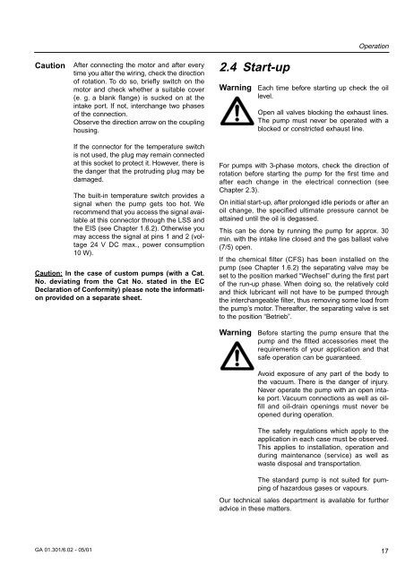
2.4 Start-up<br />
Warning<br />
Operation<br />
Each time before starting up check the oil<br />
level.<br />
Open all valves blocking the exhaust lines.<br />
The pump must never be operated with a<br />
blocked or constricted exhaust line.<br />
If the connector for the temperature switch<br />
is not used, the plug may remain connected<br />
at this socket to protect it. However, there is<br />
the danger that the protruding plug may be<br />
damaged.<br />
The built-in temperature switch provides a<br />
signal when the pump gets too hot. We<br />
recommend that you access the signal available<br />
at this connector through the LSS and<br />
the EIS (see Chapter 1.6.2). Otherwise you<br />
may access the signal at pins 1 and 2 (voltage<br />
24 V DC max., power consumption<br />
10 W).<br />
Caution: In the case of custom pumps (with a Cat.<br />
No. deviating from the Cat No. stated in the EC<br />
Declaration of Conformity) please note the information<br />
provided on a separate sheet.<br />
For pumps with 3-phase motors, check the direction of<br />
rotation before starting the pump for the first time and<br />
after each change in the electrical connection (see<br />
Chapter 2.3).<br />
On initial start-up, after prolonged idle periods or after an<br />
oil change, the specified ultimate pressure cannot be<br />
attained until the oil is degassed.<br />
This can be done by running the pump for approx. 30<br />
min. with the intake line closed and the gas ballast valve<br />
(7/5) open.<br />
If the chemical filter (CFS) has been installed on the<br />
pump (see Chapter 1.6.2) the separating valve may be<br />
set to the position marked “Wechsel” during the first part<br />
of the run-up phase. When doing so, the relatively cold<br />
and thick lubricant will not have to be pumped through<br />
the interchangeable filter, thus removing some load from<br />
the pump’s motor. Thereafter, the separating valve is set<br />
to the position “Betrieb”.<br />
Warning<br />
Before starting the pump ensure that the<br />
pump and the fitted accessories meet the<br />
requirements of your application and that<br />
safe operation can be guaranteed.<br />
Avoid exposure of any part of the body to<br />
the vacuum. There is the danger of injury.<br />
Never operate the pump with an open intake<br />
port. <strong>Vacuum</strong> connections as well as oilfill<br />
and oil-drain openings must never be<br />
opened during operation.<br />
The safety regulations which apply to the<br />
application in each case must be observed.<br />
This applies to installation, operation and<br />
during maintenance (service) as well as<br />
waste disposal and transportation.<br />
The standard pump is not suited for pumping<br />
of hazardous gases or vapours.<br />
Our technical sales department is available for further<br />
advice in these matters.<br />
GA 01.301/6.02 - 05/01<br />
17


