

Leybold D65BCS, D40BCS, Instruction Manual - Ideal Vacuum ...
Leybold D65BCS, D40BCS, Instruction Manual - Ideal Vacuum ...
Leybold D65BCS, D40BCS, Instruction Manual - Ideal Vacuum ...

Create successful ePaper yourself
Turn your PDF publications into a flip-book with our unique Google optimized e-Paper software.
Maintenance<br />
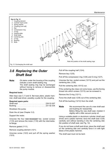
Key to Fig. 12<br />
1 Coupling element<br />
2 Cylinder head screw<br />
3 Spring washer<br />
4 Coupling (one half)<br />
5 Key<br />
6 Compression ring<br />
7 O-ring<br />
8 Holding plate<br />
9 Shaft seals<br />
10 Centering disk<br />
11 O-ring<br />
12 Bushing<br />
13 Bolts<br />
Note the position of the shaft sealing rings<br />
Fig. 12 Exchanging the shaft seal<br />
3.6 Replacing the Outer<br />
Shaft Seal<br />
Note<br />
Oil stains under the housing of the coupling<br />
indicate a worn shaft sealing ring.<br />
The shaft sealing ring may be exchanged<br />
without having to remove or disassemble<br />
the pump module.<br />
Required tools:<br />
Allen keys size 3, 5 and 8, flat-nose pliers, plastic hammer,<br />
shaft seal driver, possibly a puller for the coupling.<br />
Required spare parts:<br />
Shaft seal . . . . . . . . . . . . . . . . . . . . . . . . . 239 53 007<br />
Bushing . . . . . . . . . . . . . . . . . . . . . . . . . . . 231 92 034<br />
Shutdown the pump.<br />
Drain the oil (see Chapter 3.2).<br />
Support the motor.<br />
Unscrew the four non-recessed hex. socket screws<br />
(11/5) and remove the motor (11/6) with the intermediate<br />
flange.<br />
Remove gasket (11/1).<br />
Remove coupling element (12/1).<br />
Unscrew screw (12/2) and pull off the spring washer<br />
(12/3).<br />
Pull off the coupling half (12/4).<br />
Remove key (12/5).<br />
Pull off the compression ring (12/6) and O-ring (12/7).<br />
Unscrew the hex. socket screws (12/13) and pull out the<br />
centering disc (12/8).<br />
Pull the centering disk (10/12) out.<br />
If the centering disc does not come loose, use the forcing<br />
thread into which screws (12/13) can be screwed in.<br />
Remove the O-ring (12/11).<br />
Force the shaft seal (12/9) out of the centering disk.<br />
Pull off the bushing (12/12) from the shaft.<br />
Note<br />
We recommend the use of a new shaft seal<br />
and bushing for reassembly.<br />
Before fitting the new shaft seal, moisten it<br />
slightly with a little vacuum pump oil.<br />
Using a suitable plastic or aluminium cylinder (shaft seal<br />
driver) and a plastic hammer, force the shaft seal (12/9)<br />
carefully and without bending it into the centering disk<br />
(for position of shaft seal, see Fig. 12).<br />
If you do not have a shaft seal driver, place the shaft seal<br />
on the centering disk and carefully force it in with light<br />
blows of the plastic hammer.<br />
The shaft seal must not be bent.<br />
GA 01.301/6.02 - 05/01<br />
25


