

Leybold D65BCS, D40BCS, Instruction Manual - Ideal Vacuum ...
Leybold D65BCS, D40BCS, Instruction Manual - Ideal Vacuum ...
Leybold D65BCS, D40BCS, Instruction Manual - Ideal Vacuum ...

Create successful ePaper yourself
Turn your PDF publications into a flip-book with our unique Google optimized e-Paper software.
Description<br />
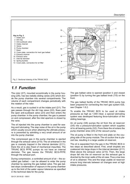
Key to Fig. 2<br />
1 Intake port<br />
2 Dirt trap<br />
3 Anti-suckback valve<br />
4 Intake channel<br />
5 Vanes<br />
6 Pump chamber<br />
7 Rotor<br />
8 Cover plate, connection for inert gas ballast<br />
9 Exhaust channel<br />
10 Exhaust valve<br />
11 Internal demister<br />
12 Spring buckles<br />
13 Cover plate, connection for oil filter<br />
Fig. 2 Sectional drawing of the TRIVAC BCS<br />
1.1 Function<br />
The rotor (2/7), mounted eccentrically in the pump housing<br />
(2/6), has two radially sliding vanes (2/5) which divide<br />
the pump chamber into several compartments. The<br />
volume of each compartment changes periodically with<br />
the rotation of the rotor.<br />
As a result, gas is sucked in at the intake port (2/1). The<br />
gas passes through the dirt trap sieve (2/2), flows past<br />
the open anti-suckback valve (2/3) and then enters the<br />
pump chamber. In the pump chamber, the gas is passed<br />
on and compressed, after the inlet aperture is closed by<br />
the vane.<br />
The oil injected into the pump chamber is used for sealing<br />
and lubricating. The slap noise of the oil in the pump<br />
which usually occurs when attaining the ultimate pressure<br />
is prevented by admitting a very small amount of air<br />
into the pump chamber.<br />
The compressed gas in the pump chamber is ejected<br />
through the exhaust valve (2/10). The oil entrained in the<br />
gas is coarsely trapped in the internal demister (2/11);<br />
there the oil is also freed of mechanical impurities. The<br />
TRIVAC BCS PFPE pumps do not have an internal<br />
demister. The gas leaves the TRIVAC BCS-PFPE<br />
through the exhaust port.<br />
During compression, a controlled amount of air – the socalled<br />
gas ballast – can be allowed to enter the pump<br />
chamber by opening the gas ballast valve. The gas ballast<br />
stops condensation of vapours in the pump chamber<br />
up to the limit of the water vapour tolerance as specified<br />
in the technical data for the pump.<br />
GA 01.301/6.02 - 05/01<br />
The gas ballast valve is opened (position I) and closed<br />
(position 0) by turning the gas ballast knob (7/5) on the<br />
front.<br />
The gas ballast facility of the TRIVAC BCS pump has<br />
been prepared for connecting the inert gas system IGS,<br />
see Chapter 1.6.2.<br />
To enable the TRIVAC BCS to be used at intake<br />
pressures as high as 1,000 mbar, a special lubricating<br />
system was developed featuring force-lubrication of the<br />
sliding bearings.<br />
An oil pump (3/6) pumps the oil from the oil reservoir<br />
(3/5) into a pressure-lubrication system which supplies<br />
oil to all bearing points (3/2). From there the oil enters the<br />
pump chamber area (3/4) of the vacuum pump.<br />
The oil pump is fitted in the front end plate on the coupling<br />
side of the pump module. The oil suction line is placed<br />
low, resulting in a large usable oil reservoir.<br />
The oil is separated from the gas in the TRIVAC BCS in<br />
two steps as described above. First, small droplets are<br />
coalesced into large drops in the internal demister (2/11)<br />
fitted above the exhaust valve (2/10). Then, the large<br />
drops fall into the oil reservoir as the exhaust gas is<br />
diverted by the inner walls of the oil case. Thus a low loss<br />
of oil is obtained. This and the large usable oil reservoir<br />
ensure long intervals between oil changes even at high<br />
intake pressures.<br />
7


