Errata Sheet - Infineon
Errata Sheet - Infineon
Errata Sheet - Infineon

You also want an ePaper? Increase the reach of your titles
YUMPU automatically turns print PDFs into web optimized ePapers that Google loves.
<strong>Errata</strong> <strong>Sheet</strong><br />
XC161CS-32F, (E)ES-BB, BB<br />
Application Hints<br />
SCU_X.H1 Shutdown handshake by software reset (SRST) instruction<br />
In the pre-reset phase of the software reset instruction, the SCU requests a shutdown<br />
from the active modules equipped with shutdown handshake (see section Peripheral<br />
Shutdown Handshake (6.3.3) in chapter Central System Control Functions in the User's<br />
Manual). The pre-reset phase is complete as soon as all modules acknowledge the<br />
shutdown state.<br />
As a consequence, e.g. the A/D converter will only acknowledge the request after the<br />
current conversion is finished (fixed channel single conversion mode), or after<br />
conversion of channel 0 (auto scan single conversion mode). If the 'Wait for Read Mode'<br />
mode is selected (bit ADWR = 1), the ADC does not acknowledge the request if the<br />
conversion result from register ADC_DAT has not been read.<br />
Therefore, before the SRST instruction is executed, it is recommended e.g. in the<br />
continuous (fixed or auto scan) conversion modes to switch to fixed channel single<br />
conversion mode (ADM = 00 B ) and perform one last conversion in order to stop the ADC<br />
in a defined way. In the auto scan conversion modes, this switch is performed after<br />
conversion of channel 0. If a 0-to-1 transition is forced in the start bit ADST by software,<br />
a new conversion is immediately started. If the 'Wait for Read Mode' is selected, register<br />
ADC_DAT must be read after the last conversion is finished.<br />
The external bus controller e.g. may not acknowledge a shutdown request if bus<br />
arbitration is enabled and the HOLD input is asserted low.<br />
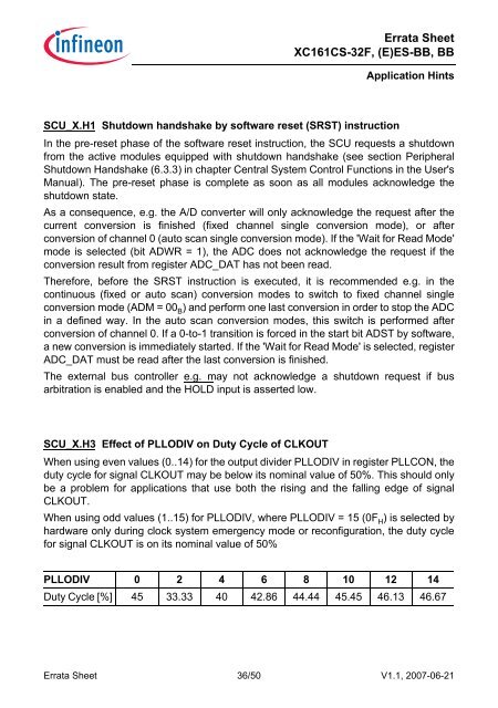
SCU_X.H3 Effect of PLLODIV on Duty Cycle of CLKOUT<br />
When using even values (0..14) for the output divider PLLODIV in register PLLCON, the<br />
duty cycle for signal CLKOUT may be below its nominal value of 50%. This should only<br />
be a problem for applications that use both the rising and the falling edge of signal<br />
CLKOUT.<br />
When using odd values (1..15) for PLLODIV, where PLLODIV = 15 (0F H ) is selected by<br />
hardware only during clock system emergency mode or reconfiguration, the duty cycle<br />
for signal CLKOUT is on its nominal value of 50%<br />
PLLODIV 0 2 4 6 8 10 12 14<br />
Duty Cycle [%] 45 33.33 40 42.86 44.44 45.45 46.13 46.67<br />
<strong>Errata</strong> <strong>Sheet</strong> 36/50 V1.1, 2007-06-21