Patch Antenna Based on Metamaterials for a ... - Radioengineering
Patch Antenna Based on Metamaterials for a ... - Radioengineering
Patch Antenna Based on Metamaterials for a ... - Radioengineering

You also want an ePaper? Increase the reach of your titles
YUMPU automatically turns print PDFs into web optimized ePapers that Google loves.
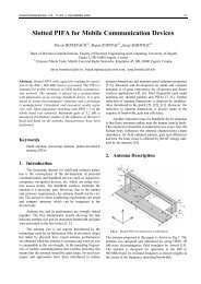
66 E. UGARTE-MUÑOZ, F. J. HERRAIZ-MARTÍNEZ, V. GONZÁLEZ-POSADAS, D. SEGOVIA-VARGAS, PATCH ANTENNA BASED …<br />
<str<strong>on</strong>g>Patch</str<strong>on</strong>g> <str<strong>on</strong>g>Antenna</str<strong>on</strong>g> <str<strong>on</strong>g>Based</str<strong>on</strong>g> <strong>on</strong> <strong>Metamaterials</strong><br />
<strong>for</strong> a RFID Transp<strong>on</strong>der<br />
Eduardo UGARTE-MUÑOZ 1 , Francisco Javier HERRAIZ-MARTÍNEZ 1 ,<br />
Vicente GONZÁLEZ-POSADAS 2 , Daniel SEGOVIA-VARGAS 1<br />
1<br />
Dept. of Signal Theory and Communicati<strong>on</strong>s, Carlos III University of Madrid. Avenida de la Universidad 30, 28911,<br />
Leganés, Madrid, Spain<br />
2 Departamento de Ingeniería audiovisual y comunicaci<strong>on</strong>es, Universidad Politécnica de Madrid. Carretera de Valencia<br />
Km.7, 28031, Madrid, Spain<br />
dani@tsc.uc3m.es<br />
Abstract. In this paper a self-diplexed antenna is proposed<br />
<strong>for</strong> a RFID transp<strong>on</strong>der applicati<strong>on</strong>. The development<br />
cycle is divided into two stages: antenna design and filters<br />
design. The antenna is based <strong>on</strong> a square microstrip patch<br />
filled with metamaterial structures. The inclusi<strong>on</strong> of these<br />
structures allows simultaneous operati<strong>on</strong> over several<br />
frequencies, which can be arbitrarily chosen. The antenna<br />
working frequencies are chosen to be 2.45 GHz (receiver)<br />
and 1.45 GHz (transmitter). In additi<strong>on</strong>, the antenna is fed<br />
through two orthog<strong>on</strong>al coupled microstrip lines, what<br />
provides higher isolati<strong>on</strong> between both ports. Some filters<br />
based <strong>on</strong> metamaterial particles are coupled or c<strong>on</strong>nected<br />
to the antenna feeding microstrip lines to avoid undesired<br />
interferences. This approach avoids using of an external<br />
filter or diplexer, providing larger size reducti<strong>on</strong> and<br />
a compact self-diplexed antenna.<br />
Keywords<br />
<strong>Metamaterials</strong>, self-diplexed antennas, RFID, microstrip<br />
patch antennas.<br />
1. Introducti<strong>on</strong><br />
In recent years automatic identificati<strong>on</strong> procedures<br />
(Auto-ID) have become very popular in many industrial<br />
services, purchasing and distributi<strong>on</strong> logistics, manufacturing<br />
companies... The barcode labels, that were a revoluti<strong>on</strong><br />
in identificati<strong>on</strong> systems some years ago, are being<br />
found to be inadequate in an increasing number of cases.<br />
Barcodes are extremely cheap, but they have a limited<br />
storage capacity (<strong>on</strong>ly a number) and cannot be reprogrammed.<br />
The optimal soluti<strong>on</strong> is the storage of data in a chip,<br />
which can be read out without mechanical c<strong>on</strong>tact (c<strong>on</strong>tactless).<br />
These c<strong>on</strong>tact-less ID systems are called RFID (Radio<br />
Frequency Identificati<strong>on</strong>) [1], [2]. A RFID system is<br />
<strong>for</strong>med by two devices: the transp<strong>on</strong>der and the reader. The<br />
transp<strong>on</strong>der is placed inside the object to be identified,<br />
which transmits the data to the reader when it is interrogated.<br />
Till now, RFID systems in microwave range usually<br />
work at the same frequency in both links, using a procedure<br />
called modulated backscatter. This approach hinders<br />
the design of the reader and requires higher transmissi<strong>on</strong><br />
power from the transp<strong>on</strong>der to allow a proper in<strong>for</strong>mati<strong>on</strong><br />
recepti<strong>on</strong> at the reader side.<br />
Another widespread method is based <strong>on</strong> a frequency<br />
doubler in the transp<strong>on</strong>der (as a diode) to answer the reader<br />
using a frequency which is the double of the interrogati<strong>on</strong><br />
<strong>on</strong>e (1:2 ratio). Although this system is simple, it is not<br />
optimum since the most power restricted link (from the<br />
transp<strong>on</strong>der to the reader) is the <strong>on</strong>e with larger path losses<br />
what limits the system reach.<br />
There<strong>for</strong>e, by taking into account all menti<strong>on</strong>ed reas<strong>on</strong>s,<br />
the optimal soluti<strong>on</strong> is the use of a dual-frequency<br />
system in the RFID transp<strong>on</strong>der. This approach allows the<br />
design of transp<strong>on</strong>ders which are interrogated at a frequency<br />
f 0 and transmit at a lower frequency (f 0 /n, where n<br />
is an arbitrary number not <strong>for</strong>ced to be an integer number).<br />
This fact reduces the losses in the power restricted link and<br />
diminishes the power requirements in the transp<strong>on</strong>der.<br />
There exist different approaches to manufacture this dualfrequency<br />
system. The simplest <strong>on</strong>e c<strong>on</strong>sists of two different<br />
antennas, but this design cannot be integrated into a<br />
small device and is very expensive. Another soluti<strong>on</strong> is the<br />
use of a dual-frequency antenna with a diplexer. It would<br />
be desirable to develop a self-diplexed dual-frequency<br />
antenna to achieve smaller size and cheaper devices.<br />
In this paper, a self-diplexed dual-frequency patch<br />
antenna <strong>for</strong> a RFID transp<strong>on</strong>der is proposed. These characteristics<br />
are achieved by using a microstrip patch with<br />
metamaterial structures.<br />
<strong>Metamaterials</strong> [3] have been used to develop microwave<br />
circuits and antennas with unusual properties [4-14].<br />
Moreover, due to the frequency-selective resp<strong>on</strong>se of<br />
metamaterial based Transmissi<strong>on</strong> Lines (TLs), miniaturized<br />
filters can be developed [9-11]. Recently, the authors have
RADIOENGINEERING, VOL. 17, NO. 2, JUNE 2008 67<br />
proposed the use of c<strong>on</strong>venti<strong>on</strong>al microstrip patches filled<br />
with metamaterial structures to achieve multi-frequency<br />
operati<strong>on</strong> [13], [14]. The design procedure of the selfdiplexed<br />
antenna is as follows:<br />
1. Design of the dual-frequency antenna at 1.45 GHz<br />
and 2.45 GHz with two isolated ports (e.g. isolati<strong>on</strong> higher<br />
than 20 dBs). The receiving frequency (2.45 GHz) is <strong>on</strong>e<br />
of the standardized bands in RFID recepti<strong>on</strong>, while the<br />
transmitting band of an RFID transp<strong>on</strong>der is not defined in<br />
the standard [1]. We have decided to transmit at 1.45 GHz,<br />
because this band allows us to filter the undesired res<strong>on</strong>ances<br />
with simple structures. Moreover, the path losses at<br />
this frequency are c<strong>on</strong>siderably smaller than at a frequency<br />
closer to the receiving <strong>on</strong>e. This antenna will be designed<br />
with a patch antenna filled with metamaterial structures<br />
and fed through two coupled microstrip lines. This feeding<br />
approach implies an improvement with respect to the<br />
authors’ previous works to obtain higher isolati<strong>on</strong> between<br />
ports, because the antennas presented in [13], [14] are fed<br />
through coaxial probes what does not provide large isolati<strong>on</strong><br />
between ports (12 dB approx. in [14]).<br />
2. Coupled or c<strong>on</strong>nected metamaterial particles to the<br />
feeding lines to avoid undesired frequencies. Two filtering<br />
strategies are investigated: the use of notch filters to eliminate<br />
the undesired frequencies close to the working bands<br />
and the use of band-pass filters which allow the transmissi<strong>on</strong><br />
at the working bands.<br />
The paper is organized as follows. The antenna design<br />
and the manufactured prototype are presented in Secti<strong>on</strong><br />
2. Secti<strong>on</strong> 3 is devoted to the filters: two proposed<br />
filtering approaches are compared and an experimental<br />
example is provided. Lastly, Secti<strong>on</strong> 4 gives the c<strong>on</strong>clusi<strong>on</strong>.<br />
2. <str<strong>on</strong>g>Antenna</str<strong>on</strong>g> Design and Experimental<br />
Results<br />
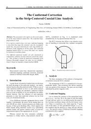
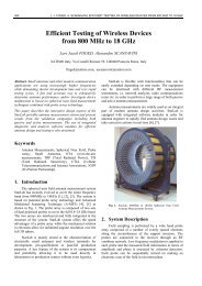
The dual-frequency antenna is based <strong>on</strong> a squared<br />
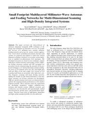
microstrip patch filled with mushroom structures (Fig. 1)<br />
[13], [14]. These mushroom structures [15] behave as Left-<br />
Handed (LH) media, allowing the propagati<strong>on</strong> of backward<br />
waves [16]. If we c<strong>on</strong>sider propagati<strong>on</strong> al<strong>on</strong>g <strong>on</strong>e main<br />
directi<strong>on</strong>, the equivalent antenna Transmissi<strong>on</strong> Line (TL)<br />
model is composed of a LH secti<strong>on</strong> between two RH<br />
secti<strong>on</strong>s (Fig. 2) [13].<br />
All the antenna eigen-frequencies satisfy the res<strong>on</strong>ant<br />
c<strong>on</strong>diti<strong>on</strong>:<br />
βn L = nπ<br />
(1)<br />
where L is the equivalent TL length and n is the res<strong>on</strong>ant<br />
index.<br />
If it is taken into account that the propagati<strong>on</strong><br />
c<strong>on</strong>stant is positive and linear in the RH secti<strong>on</strong>s and<br />
negative and proporti<strong>on</strong>al to 1/f in the LH secti<strong>on</strong>, then, the<br />
equati<strong>on</strong> (1) can be rewritten as:<br />
RH LH k2<br />
βn L = βn<br />
d + βn<br />
l = k1<br />
fnd<br />
− l =<br />
f<br />
n<br />
nπ<br />
where k 1 and k 2 are c<strong>on</strong>stants; d and l are the equivalent<br />
lengths of the RH and LH secti<strong>on</strong>s, respectively. In this<br />
case, it is possible to obtain modes with negative, zero or<br />
positive index <strong>on</strong> the c<strong>on</strong>trary to c<strong>on</strong>venti<strong>on</strong>al patches.<br />
Specifically, <strong>for</strong> a LH secti<strong>on</strong> composed of M unit cells, n<br />
takes values:<br />
(2)<br />
n = −M<br />
+ 1 , −M<br />
+ 2,...,0, + 1, + 2,...<br />
(3)<br />
Fig. 1. Microstrip patch filled with LH structures.<br />
Fig. 2. Equivalent TL model of the antenna.<br />
In our case, M is 2 in order to obtain the n = -1 mode as the<br />
fundamental <strong>on</strong>e and avoid undesired lower modes. This<br />
fundamental mode presents half-wavelength electric field<br />
distributi<strong>on</strong> as the fundamental mode of a c<strong>on</strong>venti<strong>on</strong>al<br />
patch antenna, which leads to a dipolar (broadside and <strong>on</strong>e<br />
beam) radiati<strong>on</strong> pattern. Moreover, the equivalent mode to<br />
the fundamental <strong>on</strong>e of a c<strong>on</strong>venti<strong>on</strong>al patch antenna is<br />
also present (n = +1). For these reas<strong>on</strong>s, a dual-frequency<br />
antenna can be developed by using n = ±1 modes at the<br />
same time. Moreover, if the antenna is fed through two<br />
orthog<strong>on</strong>al ports placed at the two main directi<strong>on</strong>s, the<br />
modes [-1,0], [0,-1], [+1,0] and [0,+1] (where the first<br />
index is related to the propagati<strong>on</strong> al<strong>on</strong>g the first directi<strong>on</strong><br />
and the sec<strong>on</strong>d index to the orthog<strong>on</strong>al directi<strong>on</strong>) can be<br />
excited. For RFID applicati<strong>on</strong>, f [0,+1] will be set to<br />
2.45 GHz and f [-1,0] to 1.45 GHz. The other res<strong>on</strong>ances will<br />
be filtered to avoid undesired interferences.<br />
The final designed antenna is shown in Fig. 3. It is<br />
based <strong>on</strong> a 37.4 mm side length square patch <strong>on</strong> a PP<br />
substrate with h = 4 mm and ε r = 2.2. The dimensi<strong>on</strong>s of<br />
the mushrooms are 11 mm × 14 mm, the vias radius is<br />
0.35 mm and the gaps are 0.20 mm. The patch is fed<br />
through two 50 Ω coupled microstrip lines placed at two<br />
orthog<strong>on</strong>al directi<strong>on</strong>s. This feeding technique provides<br />
high isolati<strong>on</strong> between both ports. The dimensi<strong>on</strong>s of the<br />
lines are 6.00 mm × 37 mm (Port 1) and 6.00 mm × 22 mm<br />
(Port 2). The Port 1 feeding line is placed 4.70 mm bey<strong>on</strong>d<br />
the edge of the patch, while the Port 2 feeding line is
68 E. UGARTE-MUÑOZ, F. J. HERRAIZ-MARTÍNEZ, V. GONZÁLEZ-POSADAS, D. SEGOVIA-VARGAS, PATCH ANTENNA BASED …<br />
placed 1.70 mm inside the patch to improve the match at<br />
each port. The substrate is implemented by 2 slits with 2<br />
mm height each <strong>on</strong>e, placing the feeding metallizati<strong>on</strong> over<br />
the lower slit.<br />
The electric field distributi<strong>on</strong>s at the two working modes<br />
(computed with CST ® ) are shown in Fig. 4. In both cases<br />
the electric field distributi<strong>on</strong> has half-wavelength electric<br />
length. The res<strong>on</strong>ant behavior of the mushrooms can be<br />
observed in the first mode. This is the reas<strong>on</strong> why this<br />
additi<strong>on</strong>al mode is obtained. On the other hand, the sec<strong>on</strong>d<br />
mode is basically the c<strong>on</strong>venti<strong>on</strong>al <strong>on</strong>e of the patch. Moreover,<br />
there is no power transmissi<strong>on</strong> between both ports at<br />
the working frequencies. This is the reas<strong>on</strong> because it provides<br />
high level of isolati<strong>on</strong> between the ports. The simulated<br />
radiati<strong>on</strong> patters (CST ® ) at these two frequencies are<br />
also plotted. The patch-like radiati<strong>on</strong> pattern is obtained at<br />
both frequencies, as desired. Fig. 5 shows the simulated [S]<br />
parameters of the antenna. Return losses are |S 11 | =<br />
-21 dB at f [-1,0] = 1.45 GHz and |S 22 | = -16.7 dB at f [0,+1] =<br />
2.45 GHz. The isolati<strong>on</strong> is -46 dB at the first working frequency<br />
and -20 dB at the sec<strong>on</strong>d <strong>on</strong>e. A prototype of this<br />
antenna has been manufactured (Fig. 6). The experimental<br />
[S] parameters of this antenna are also plotted in Fig. 5. It<br />
can be seen that simulati<strong>on</strong>s and measurements agree.<br />
Fig. 3. Final design of the antenna.<br />
Fig. 5. Simulated and measured [S] parameters of the antenna of<br />
Fig. 3.<br />
Fig. 6. Picture of the manufactured prototype.<br />
Fig. 4. Simulated electric fields distributi<strong>on</strong>s and radiati<strong>on</strong><br />
patters of the proposed antenna of Fig. 3 at the two<br />
working frequencies.<br />
Fig. 7. Measured radiati<strong>on</strong> patterns of the manufactured<br />
prototype. (a) Transmitter and (b) receiver frequency.
RADIOENGINEERING, VOL. 17, NO. 2, JUNE 2008 69<br />
The radiati<strong>on</strong> patterns at the two working frequencies<br />
are shown in Fig. 7. Both frequencies present a patch-like<br />
radiati<strong>on</strong> pattern, as expected. The crosspolar comp<strong>on</strong>ents<br />
at the main directi<strong>on</strong> are -25 dB at the first frequency and<br />
-20 dB at the sec<strong>on</strong>d <strong>on</strong>e. There are some undesired modes<br />
which will be filtered out in the next Secti<strong>on</strong> to avoid interferences<br />
and improve the isolati<strong>on</strong>: two modes ([0,+1] and<br />
a higher-order mode) at port 1 near the working frequency<br />
of the sec<strong>on</strong>d port (2.45 GHz) and a mode ([0,-1]) at port 2<br />
near the working frequency of port 1 (1.45 GHz).<br />
3. Filters Design<br />
The filters are based <strong>on</strong> metamaterial particles coupled<br />
or c<strong>on</strong>nected to the feeding microstrip lines. Two<br />
types of filtering strategies have been investigated: notch<br />
filters and band-pass filters.<br />
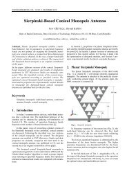
The proposed particles <strong>for</strong> the notch filters are Square<br />
Split Ring Res<strong>on</strong>ators (SSRR) and Square Spiral Ring<br />
Res<strong>on</strong>ators (SSR2), which were studied in circular geometry<br />
in [12]. These structures are coupled to the transmissi<strong>on</strong><br />
lines and provide a stop-band in the vicinity of their selfres<strong>on</strong>ant<br />
frequencies. The main difference between both<br />
types of particles is the size, because the self-res<strong>on</strong>ant<br />
frequency of a SSR2 is half the self-res<strong>on</strong>ant frequency of<br />
the SSRR with similar dimensi<strong>on</strong>s. This implies a larger<br />
degree miniaturizati<strong>on</strong> <strong>for</strong> SSR2.<br />
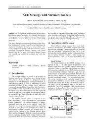
Fig. 8 shows the sketches and the parameters of the<br />
metamaterials particles proposed <strong>for</strong> the notch-filters. Fig.<br />
9 provides an example <strong>on</strong> how these particles are coupled<br />
to the feeding TLs. This example corresp<strong>on</strong>ds to the case<br />
of port 1 in which two res<strong>on</strong>ances must be filtered. The<br />
filters have been designed <strong>for</strong> both ports and using the two<br />
types of particles. The sides of the squares (I L ) designed <strong>for</strong><br />
port 1 are 8.05 mm and 8.95 mm <strong>for</strong> the SSRR. The spacing<br />
between both stages (S) is 15 mm. On the other hand,<br />
the dimensi<strong>on</strong>s (I L ) <strong>for</strong> the SSR2 are 4.95 mm and 4.53 mm<br />
with an 8 mm separati<strong>on</strong>. At port 2 the side of the square<br />
(I L ) is 12.2 mm <strong>for</strong> the SSRR and 6.45 mm <strong>for</strong> the SSR2.<br />
All the gaps between the rings and the lines are 0.20 mm.<br />
The gaps inside the rings (d) are 0.40 mm and the copper<br />
width (c) of each line is 0.20 mm. The substrate is polypropylene<br />
(PP) with h = 2 mm and ε r = 2.2.<br />
Fig. 9. Example of two notch filters based <strong>on</strong> SSRR coupled to<br />
a feeding transmissi<strong>on</strong> line. This example corresp<strong>on</strong>ds to<br />
the port 1 case in which two res<strong>on</strong>ances are filtered.<br />
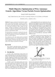
These four filters have been simulated (CST ® ). Simulati<strong>on</strong><br />
results <strong>for</strong> the filters based <strong>on</strong> SRR2 are shown in Fig. 10.<br />
The stop-bands of the proposed filters match with the undesired<br />
frequencies of the antenna. The results are similar<br />
<strong>for</strong> the case of the filters based <strong>on</strong> SSRR, but the bandwidth<br />
of the SSR2 based filters is slightly narrower. Although<br />
these filters work properly, as showed be<strong>for</strong>e, some<br />
drawbacks can be enumerated: the bandwidth of these<br />
notch-filters is narrower than the undesired res<strong>on</strong>ances of<br />
the antenna. Thus, more stages should be added to eliminate<br />
completely the undesired res<strong>on</strong>ances. Moreover, <strong>on</strong>e<br />
filter must be designed <strong>for</strong> each undesired res<strong>on</strong>ances. For<br />
these reas<strong>on</strong>s, we propose the sec<strong>on</strong>d type of filters (bandpass<br />
filters) which overcome all these drawbacks.<br />
Fig.10.a Simulati<strong>on</strong> results of the notch filters based <strong>on</strong> SSR2 at<br />
port 1, antenna |s 11 | and |s 22 | are also plotted.<br />
Fig. 8. Proposed metamaterial particles and their parameters <strong>for</strong><br />
the notch-filters. (a) SSRR. (b) SSR2.<br />
Fig.10.b Simulati<strong>on</strong> results of the notch filters based <strong>on</strong> SSR2 at<br />
port 2, antenna |s 11 | and |s 22 | are also plotted. a) at port 1,
70 E. UGARTE-MUÑOZ, F. J. HERRAIZ-MARTÍNEZ, V. GONZÁLEZ-POSADAS, D. SEGOVIA-VARGAS, PATCH ANTENNA BASED …<br />
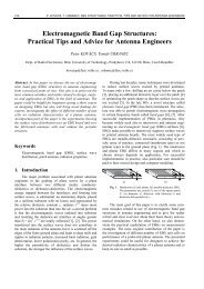
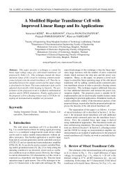
The passband filters are implemented by c<strong>on</strong>necting<br />
metamaterial particles in series with the feeding line. These<br />
particles are Double Square Open Split Ring Res<strong>on</strong>ators<br />
(DSOSRR), which are based <strong>on</strong> the Open Split Ring Res<strong>on</strong>ator<br />
(OSRR) presented in [11], but our particles do not<br />
have a window in the ground plane and each of them are<br />
mirrored with respect to the feeding line. Fig. 11 shows the<br />
sketch of the proposed filters and their dependence parameters.<br />
been investigated: notch filters and band-pass filters. For<br />
the first type of filters SSRR and SRR2 particles have been<br />
c<strong>on</strong>sidered, while the band-pass filters are based <strong>on</strong> the<br />
particle DSOSRR. The passband filters are more suitable<br />
<strong>for</strong> this applicati<strong>on</strong>, because their frequency resp<strong>on</strong>se allows<br />
transmitting the desired signal and rejects all the undesired<br />
frequencies of the antenna with <strong>on</strong>ly <strong>on</strong>e filter per<br />
port.<br />
Fig. 11. Band-pass filter based <strong>on</strong> DSOSRR and its parameters.<br />
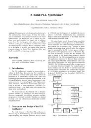
The passband filters <strong>for</strong> the port 1 (1.45 GHz) and<br />
port 2 (2.45 GHz) have been designed, manufactured and<br />
measured, showing good results in both cases. As an example<br />
the results <strong>for</strong> the port 2 filter are provided. The<br />
parameters of this filter are: I L = 3.83 mm, gap = 0.60 mm,<br />
c = 0.20 mm, d = 0.40 mm, e = 0.60 mm. The substrate is<br />
Arl<strong>on</strong> ® 1000 (h = 1.27 mm and ε r = 10). Fig. 12 shows the<br />
picture of the manufactured photograph and the simulated<br />
(CST ® ) and measured [S] parameters of this filter. There is<br />
a small frequency shift between the simulated and measured<br />
results due to the tolerances of our manufacturing<br />
process. The measured inserti<strong>on</strong> losses of this filter are<br />
1.2 dB. As it has been dem<strong>on</strong>strated, these passband filters<br />
have a bandwidth broader than the <strong>on</strong>e presented by the<br />
antennas and <strong>on</strong>ly <strong>on</strong>e filter per port is needed in order to<br />
allow the transmissi<strong>on</strong> of the desired frequency and reject<br />
all the undesired frequencies.<br />
(a)<br />
4. C<strong>on</strong>clusi<strong>on</strong><br />
A novel self-diplexed antenna <strong>for</strong> RFID applicati<strong>on</strong><br />
has been presented. First, it has been shown that it is possible<br />
to obtain an antenna with two dipolar modes (n = ±1)<br />
by filling a microstrip patch with LH structures. Then, an<br />
antenna working at f [-1,0] = 1.45 GHz and f [0,+1] = 2.45 GHz<br />
has been designed. These two orthog<strong>on</strong>al modes have been<br />
excited through two orthog<strong>on</strong>al coupled microstrip lines.<br />
The isolati<strong>on</strong> between the ports is 40 dB at the first frequency<br />
and 20 dB at the sec<strong>on</strong>d <strong>on</strong>e. Finally, metamaterial<br />
particles have been coupled or c<strong>on</strong>nected to the feeding<br />
lines in order to filter the undesired frequencies which are<br />
near the working frequencies. Two types of filters have<br />
(b)<br />
Fig. 12. (a) Picture of the filter prototype. (b) Simulated and<br />
measured results.<br />
Acknowledgements<br />
This work has been partially granted by the Spanish<br />
MEC under Project TEC2006-13248-C04-04/TCM. F. J.<br />
Herraiz-Martínez is recipient of a FPU grant from Spanish<br />
MEC. E. Ugarte-Muñoz is recipient of a MEC-<br />
ECI/1920/2006 grant.
RADIOENGINEERING, VOL. 17, NO. 2, JUNE 2008 71<br />
References<br />
[1] FINKENZELLER, K. RFID Handbook: Fundamentals and<br />
Applicati<strong>on</strong> in C<strong>on</strong>tactless Smart Cards and Identificati<strong>on</strong>. New<br />
York: John Wiley & S<strong>on</strong>s, 2003.<br />
[2] POBANZ, C. W., ITOH, T. A microwave n<strong>on</strong>c<strong>on</strong>tact identificati<strong>on</strong><br />
transp<strong>on</strong>der using subharm<strong>on</strong>ic interrogati<strong>on</strong>. IEEE Transacti<strong>on</strong>s <strong>on</strong><br />
Microwave Theory and Techniques, 1995, vol. 43, no. 7.<br />
[3] VESELAGO, V. The electrodynamics of substances with<br />
simultaneously negative values of ε and μ. Soviet Physics Uspekhi,<br />
1968, vol. 10, no. 4, p. 509–514.<br />
[4] LIN, I., DEVINCENTIS, M., CALOZ, C., ITOH, T. Arbitrary dualband<br />
comp<strong>on</strong>ents using composite right/left-handed transmissi<strong>on</strong><br />
lines. IEEE Transacti<strong>on</strong>s <strong>on</strong> Microwave Theory and Techniques,<br />
2004, vol. 52, p. 1142–1149.<br />
[5] ANTONIADES, M. A., ELEFTHERIADES, G. V. Compact linear<br />
lead/lag metamaterial phase shifters <strong>for</strong> broadband applicati<strong>on</strong>s.<br />
IEEE Microwave and Wireless Propagati<strong>on</strong> Letters, 2003, vol. 2,<br />
p. 103–106.<br />
[6] SCHÜßLER, M., FREESE, J., JAKOBY, R. Design of compact<br />
planar antennas using LH transmissi<strong>on</strong> lines. In Proceedings of the<br />
IEEE MTT-S Internati<strong>on</strong>al Microwave Symposium, 2004, vol. 1,<br />
p. 209–212.<br />
[7] QURESHI, F., ANTONIADES, M. A., ELEFTHERIADES, G. V.<br />
A compact and low-profile metamaterial ring antenna with vertical<br />
polarizati<strong>on</strong>. IEEE Microwave and Wireless Propagati<strong>on</strong> Letters,<br />
2005, vol. 4, p. 333–336.<br />
[8] LEE, C. J., LEONG, K. M. K. H., ITOH, T. Composite right/lefthanded<br />
transmissi<strong>on</strong> line based compact res<strong>on</strong>ant antennas <strong>for</strong> RF<br />
module integrati<strong>on</strong>. IEEE Transacti<strong>on</strong>s <strong>on</strong> <str<strong>on</strong>g>Antenna</str<strong>on</strong>g>s and Propagati<strong>on</strong>,<br />
2006, vol. 54, no. 8, p. 2283–2291.<br />
[9] GARCÍA-GARCÍA, J., MARTÍN, F., FALCONE, F., BONACHE,<br />
J., BAENA, J. D., GIL, I. , AMAT, E., LOPETEGUI, T., LASO, M.<br />
A. G., MARCOTEGUI ITURMENDI, J. A. Microwave filters with<br />
improved stopband based <strong>on</strong> sub-wavelength res<strong>on</strong>ators. IEEE<br />
Transacti<strong>on</strong>s <strong>on</strong> Microwave Theory and Techniques, 2005, vol. 53,<br />
no. 6, p. 1997–2006.<br />
[10] GIL, I., BONACHE, J., GARCÍA-GARCÍA, J., FALCONE, F.,<br />
MARTÍN, F. <strong>Metamaterials</strong> in microstrip technology <strong>for</strong> filter<br />
applicati<strong>on</strong>s. 2005 IEEE AP-S Internati<strong>on</strong>al Symposium, Vol. 1A,<br />
p. 668–671, 2005.<br />
[11] MARTEL, J., BONACHE, J., MARQUÉS, R., MARTÍN, F.,<br />
MEDINA, F. Design of wide-band semi-lumped bandpass filters<br />
using open split ring res<strong>on</strong>ators. IEEE Microwave and Wireless<br />
Comp<strong>on</strong>ents Letters, January 2007, vol. 17, no. 1.<br />
[12] BAENA, J. D., BONACHE, J., MARTÍN, F., MARQUÉS, R.,<br />
FALCONE, F., LOPETEGUI, T., G. LASO, M. A., GARCÍA, J.,<br />
GIL, I., SOROLLA, M. Equivalent circuit models <strong>for</strong> split ring<br />
res<strong>on</strong>ators and complementary split ring res<strong>on</strong>ators coupled to planar<br />
transmissi<strong>on</strong> lines. IEEE Transacti<strong>on</strong>s <strong>on</strong> Microwave Theory and<br />
Techniques, 2005, vol. 53, p. 1451–1461.<br />
[13] HERRAIZ-MARTÍNEZ, F. J., GARCÍA-MUÑOZ, L. E., GONZÁ-<br />
LEZ-POSADAS, V., SEGOVIA-VARGAS, D. Multi-frequency and<br />
dual mode patch antennas partially filled with left-handed structures.<br />
IEEE Transacti<strong>on</strong>s <strong>on</strong> <str<strong>on</strong>g>Antenna</str<strong>on</strong>g>s and Propagati<strong>on</strong>, submitted.<br />
[14] HERRAIZ-MARTÍNEZ, F. J., GONZÁLEZ-POSADAS, V., SEGO-<br />
VIA-VARGAS, D. A dual-band circularly polarized antenna based<br />
<strong>on</strong> a microstrip patch filled with left-handed structures. In EuCAP<br />
2007, Edinburgh (UK), 2007.<br />
[15] SIEVENPIPER, D., ZHANG, L., BROAS, F. J., ALEXOPULOS,<br />
N.G., YABLONOVITCH, E. High-impedance electromagnetic<br />
surfaces with a <strong>for</strong>bidden frequency band. IEEE Trans. MTT,<br />
November 1999, vol. 47, pp. 2059–2074.<br />
[16] SANADA, A., CALOZ, C., ITOH, T. Planar distributed structures<br />
with negative refractive index. IEEE Trans. <strong>on</strong> MTT, April 2004, vol.<br />
52, no. 4, pp. 1252-1263.<br />
About Authors...<br />
Eduardo UGARTE-MUÑOZ was born in Caracas, Venezuela<br />
<strong>on</strong> April 23, 1983. Currently he is about to get his<br />
degree in telecommunicati<strong>on</strong>s from Carlos III University in<br />
Madrid, Spain. At the moment he is working <strong>on</strong> CRLH<br />
antennas.<br />
Francisco Javier HERRAIZ-MARTÍNEZ was born in<br />
Cuenca, Spain, <strong>on</strong> May 3, 1983. He received the Engineer<br />
degree in telecommunicati<strong>on</strong>s from Carlos III University in<br />
Madrid, Spain, in 2006 (awarded with the first prize). He is<br />
currently working towards the Ph.D. in communicati<strong>on</strong>s at<br />
Carlos III University in Madrid. His research interests<br />
include active antennas and metamaterial applicati<strong>on</strong>s <strong>for</strong><br />
antenna and microwave circuits. Mr. Herraiz-Martínez<br />
received the Spanish Best Master Thesis Dissertati<strong>on</strong><br />
Award from the COIT/AEIT. He was finalist of the IEEE<br />
AP-S Student Paper C<strong>on</strong>test.<br />
Vicente GONZÁLEZ-POSADAS was born in Madrid<br />
(Spain) in 1968. He received the Ing. Técnico in radiocommunicati<strong>on</strong><br />
engeneering degree from the Polytechnic<br />
University of Madrid (UPM) in 1992, M.S. degree in<br />
physics in 1995, from the UNED and Ph.D degree in<br />
telecommunicati<strong>on</strong> engeneering in 2001 from the Carlos III<br />
University of Madrid. He is working now as an Assistant<br />
Professor at the Technical Telecommunicati<strong>on</strong> School in<br />
the Polytechnic University of Madrid. His interest are<br />
related to active antennas, microstrip antennas, CRLH lines<br />
and metamaterials and microwave technology. He has<br />
authored or coauthored over 60 technical c<strong>on</strong>ference,<br />
letters and journal papers.<br />
Daniel SEGOVIA-VARGAS (M’98) was born in Madrid<br />
in 1968. He received the Telecommunicati<strong>on</strong> Engineering<br />
Degree and the Ph.D. from the Polytechnic University of<br />
Madrid in 1993 and in 1998. From 1993 to 1998 he was an<br />
Assistant Professor at Valladolid University. From 1998 he<br />
is an Associate Professor at Carlos III University in Madrid<br />
where he is in charge of the Microwaves and <str<strong>on</strong>g>Antenna</str<strong>on</strong>g><br />
courses. He has authored and co-authored over 80 technical<br />
c<strong>on</strong>ference, letters and journal papers. His research<br />
areas are printed antennas and active radiators and arrays<br />
and smart antennas, LH metamaterials and passive circuits.<br />
He has also been member of the European Projects<br />
Cost260, Cost284 and COST IC0603.