Sierpinski-Based Conical Monopole Antenna - Radioengineering
Sierpinski-Based Conical Monopole Antenna - Radioengineering
Sierpinski-Based Conical Monopole Antenna - Radioengineering

You also want an ePaper? Increase the reach of your titles
YUMPU automatically turns print PDFs into web optimized ePapers that Google loves.
RADIOENGINEERING, VOL. 19, NO. 4, DECEMBER 2010 633<br />
<strong>Sierpinski</strong>-<strong>Based</strong> <strong>Conical</strong> <strong>Monopole</strong> <strong>Antenna</strong><br />
Petr VŠETULA, Zbyněk RAIDA<br />
Dept. of Radio Electronics, Brno University of Technology, Purkyňova 118, 612 00 Brno, Czech Republic<br />
xvsetu00@stud.feec.vutbr.cz, raida@feec.vutbr.cz<br />
Abstract. Planar <strong>Sierpinski</strong> monopole exhibits a multiband<br />
behavior, but its parameters in operation frequency<br />
bands are not optimal. By mapping the <strong>Sierpinski</strong> monopole<br />
on a conical surface, a symmetrical three-dimensional<br />
(3-D) structure is obtained. In this way, a larger bandwidth<br />
and a better radiation pattern is achieved. The symmetrical<br />
3D <strong>Sierpinski</strong>-based monopole is an original contribution<br />
of this paper.<br />
In the paper, different versions of the conical <strong>Sierpinski</strong>based<br />
monopole are designed, and results of simulations<br />
performed in CST Microwave Studio are mutually compared.<br />
Then, the simulated versions of the conical monopole<br />
are optimized according to specified criteria. The<br />
optimized conical <strong>Sierpinski</strong>-based monopole is manufactured<br />
and its properties are experimentally verified. Results<br />
of measuring the <strong>Sierpinski</strong>-based conical monopole<br />
antenna are published here for the first time.<br />
In Section 2, properties of a planar <strong>Sierpinski</strong> monopole<br />
and the modified gasket monopole antenna are briefly<br />
reviewed [4]. In Section 3, planar versions of antennas are<br />
projected to the conical surface [4]. Section 4 deals with<br />
the optimization of designed antennas, and Section 5 presents<br />
experimental results. Section 6 concludes the paper.<br />
2. Planar <strong>Sierpinski</strong> <strong>Monopole</strong><br />
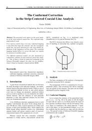
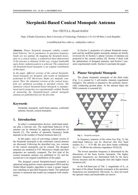
The planar <strong>Sierpinski</strong> monopole of the third order<br />
(Fig. 1) is created by 3 self-similar elements (equilateral<br />
triangles). The antenna is attached to the perfectly electrically<br />
conducting ground plane. At the antenna input, the<br />
SMA connector is assumed [4].<br />
Keywords<br />
<strong>Sierpinski</strong> monopole, multi-band antenna, conformal<br />
antenna, fractals, conical monopole.<br />
1. Introduction<br />
In today’s communication devices, multi-band antennas<br />
play a relevant role. The multi-band behavior of the<br />
antenna can be obtained by applying self-similarities of<br />
fractals [1]. The number of operation frequency bands<br />
depends on the number of fractal iterations then [2].<br />
In this paper, ways of converting a planar version of<br />
the <strong>Sierpinski</strong> monopole to the conformal, conical antenna<br />
are discussed. Following the described way, two versions<br />
of the conical monopoles can be created. The designed<br />
antennas are modeled in CST Microwave Studio and their<br />
properties are mutually compared. The first kind of the<br />
conical monopole antenna was published in [3], and the<br />
second one is an original contribution of this paper.<br />
The designed conical <strong>Sierpinski</strong>-based monopole is<br />
optimized using particle swarm optimization (PSO) and the<br />
Nelder-Mead simplex algorithm to reach a proper impedance<br />
matching in specified frequency bands. The optimized<br />
antenna is measured and results are compared with simulations.<br />
Fig. 1. <strong>Sierpinski</strong> monopole.<br />
In frequency response of the return loss (Fig. 2), the<br />
multi-band behavior can be observed (the first band<br />
reaches |S 11 | = –9.74 dB, the next three bands exhibiting<br />
|S 11 | < –10 dB for the reference impedance 50 Ω) [4].<br />
The lowest operation frequency is determined by the<br />
dimensions of the basic bowtie monopole. The higher<br />
operation frequencies are determined both by the basic<br />
bowtie structure and the triangular slots (the higher fractal<br />
iterations) [4].<br />
In the left-hand part of Tab. 1, magnitudes of S 11 at<br />
the input of the planar <strong>Sierpinski</strong> monopole at the operation<br />
frequencies are summarized. Obviously, S 11 does not reach<br />
the optimal values and bandwidths are narrow.
634 P.VŠETULA, Z. RAIDA, SIERPINSKI-BASED CONICAL MONOPOLE ANTENNA<br />
Fig. 2. Frequency response of the planar <strong>Sierpinski</strong> monopole<br />
return loss.<br />
In order to improve the impedance matching, the concept<br />
of the modified gasket monopole antenna (Fig. 3) can<br />
be adopted [3]. The vertical distance of the slot from the<br />
ground plane equals to the height of the smallest triangles<br />
of the <strong>Sierpinski</strong> structure [4].<br />
<strong>Sierpinski</strong> monopole Modified gasket monopole<br />
f [GHz] S 11 [dB] BW [MHz] f [GHz] S 11 [dB] BW [MHz]<br />
0.29 –9.74 71 0.31 –8.17 145<br />
1.08 –24.63 25 1.18 –21.34 51<br />
2.39 –15.28 180 2.66 –17.65 126<br />
4.41 –17.89 243 4.63 –33.33 48<br />
Fig. 4. Frequency response of return loss of the planar<br />
<strong>Sierpinski</strong> monopole (blue) and the gasket monopole<br />
antenna (red). Planar structures.<br />
3. <strong>Conical</strong> <strong>Sierpinski</strong>-<strong>Based</strong> <strong>Monopole</strong><br />
In order to improve the symmetry of the radiation and<br />
to make the bandwidth wider, the planar structure is mapped<br />
[3] to the conical surface (Fig. 5).<br />
Tab. 1. Return loss of the conventional <strong>Sierpinski</strong> monopole<br />
(left) and the modified gasket monopole (right) at<br />
operation frequencies. Planar structure assumed.<br />
Frequency response of S 11 of the modified gasket<br />
monopole is depicted in Fig. 4. In the right-hand part of<br />
Tab. 1, magnitudes of S 11 at operation frequencies are<br />
compared with the values of the <strong>Sierpinski</strong> monopole. The<br />
responses are similar.<br />
Fig. 3. Planar gasket monopole antenna.<br />
Radiation patterns of both planar antennas exhibit<br />
asymmetries caused by their asymmetrical geometry<br />
(Fig. 14 and Fig. 15). In order to obtain the omni-directional<br />
pattern in the horizontal plane, geometries of planar<br />
antennas are projected into the conical surface [4].<br />
Fig. 5. <strong>Conical</strong> gasket monopole antenna.<br />
Thanks to the conical shape, the omni-directional radiation<br />
and wider operation bandwidth are reached [3].<br />
Heights of segments of the conical gasket monopole are<br />
identical with lengths of segments of the planar antenna.<br />
Frequency response of the reflection coefficient at the<br />
antenna input S 11 is depicted in Fig. 7. Magnitudes of the<br />
reflection coefficient in operation frequency bands are<br />
summarized in the right part of Tab. 2.<br />
Next, the layout of the planar <strong>Sierpinski</strong> monopole<br />
was mapped to the conical surface (Fig. 6). The mapping<br />
resulted in an asymmetrical geometry. Heights of triangles<br />
of the conical antenna are identical with heights of triangles<br />
of the planar <strong>Sierpinski</strong> monopole.<br />
The frequency response of the magnitude of the reflection<br />
coefficient S 11 at the input of the conical <strong>Sierpinski</strong>-based<br />
monopole (Fig. 7) is similar to the characteristics<br />
of the planar <strong>Sierpinski</strong> monopole.
RADIOENGINEERING, VOL. 19, NO. 4, DECEMBER 2010 635<br />
4. Optimization<br />
The conical gasket monopole and the conical<br />
<strong>Sierpinski</strong>-based monopole were optimized to meet<br />
impedance matching conditions in the bands of GSM 900,<br />
GSM 1800 and Wi-Fi (see Tab. 3).<br />
Fig. 6. <strong>Conical</strong> <strong>Sierpinski</strong>-based monopole.<br />
Values of S 11 of the conical <strong>Sierpinski</strong>-based monopole<br />
in operation bands are given in the left-hand part of<br />
Tab. 2. Operation bands of the conical gasket monopole are<br />
shifted downwards, and the improvement of bandwidth<br />
with lower frequency is visible.<br />
Fig. 7. Frequency response of return loss of the conical<br />
<strong>Sierpinski</strong>-based monopole (blue) and the gasket one<br />
(red). <strong>Conical</strong> structures.<br />
Radiation patterns of the conical gasket monopole are<br />
depicted in Fig. 17. Here, the power improvement as well<br />
as the similarity of the radiation spectrum is obvious. The<br />
conical <strong>Sierpinski</strong>-based monopole produces two beams<br />
(Fig. 16), similar to a conventional monopole. Due to the<br />
symmetry of the structure in the vertical plane, an omnidirectional<br />
radiation character was achieved.<br />
Band Frequency [GHz] Bandwidth [GHz]<br />
GSM 900 0.9 0.89 – 0.96<br />
GSM 1800 1.8 1.71 – 1.88<br />
Wi-Fi (802.11b) 2.4 2.40 – 2.47<br />
Tab. 3. Operation frequency bands [5].<br />
The return loss was asked to be |S 11 | < –10 dB in all<br />
the frequency bands. In order to meet this goal, the optimization<br />
routine computed the heights of slots. The upper<br />
diameter of the monopole and the height of the whole<br />
structure remained the same.<br />
The optimal parameters are listed in Tab. 4. Frequency<br />
response of the return loss is depicted in Fig. 8.<br />
Whereas the optimization of the conical gasket monopole<br />
was not successful, the <strong>Sierpinski</strong>-based monopole shows<br />
better results.<br />
The geometry of the optimized conical <strong>Sierpinski</strong>based<br />
monopole is depicted in Fig. 9.<br />
Parameter<br />
Height [mm]<br />
Optimized conical<br />
<strong>Sierpinski</strong>-based monopole<br />
Optimized conical<br />
gasket monopole<br />
h1 124.184 85.5871<br />
h2 49.5876 28.8998<br />
h3 46.6387 19.6753<br />
Tab. 4. Resulting parameters of the optimized conical monopoles.<br />
<strong>Conical</strong> <strong>Sierpinski</strong>-based<br />
monopole<br />
<strong>Conical</strong> gasget<br />
monopole antenna<br />
f [GHz] S 11 [dB] BW [MHz] f [GHz] S 11 [dB] BW [MHz]<br />
0.38 –7.57.. - 0.24 –6.94.. -<br />
1.13 –31.01.. 76 0.60 –10.21.. 231<br />
2.42 –23.37.. 16 1.25 –8.84.. 368<br />
4.74 –18.97.. 476 2.87 –13.21.. -<br />
Tab. 2. Magnitude of S 11 at the input of the conventional<br />
<strong>Sierpinski</strong>-based monopole (left) and the conical<br />
gasket monopole antenna (right) at operation<br />
frequencies. <strong>Conical</strong> structures assumed.<br />
Fig. 8. Frequency response of return loss of the <strong>Sierpinski</strong>based<br />
monopole (blue) and the gasket one (red).<br />
<strong>Conical</strong> optimized structures.
636 P.VŠETULA, Z. RAIDA, SIERPINSKI-BASED CONICAL MONOPOLE ANTENNA<br />
<strong>Sierpinski</strong>-based antenna. The correspondence between<br />
measurements and computations is quite good.<br />
Fig. 9. Optimized conical <strong>Sierpinski</strong>-based monopole.<br />
5. Experimental Verification<br />
In order to fabricate the antenna, a planar layout<br />
(Fig. 10) is developed. The developed layout is printed on<br />
a thin substrate, and the substrate is formed into the cone.<br />
Fig. 12. Frequency response of return loss of the measured<br />
(blue) and the simulated (red) optimized fabricated<br />
conical <strong>Sierpinski</strong>-based monopole.<br />
In Tab. 5, values of the return loss in operational<br />
bands are listed. Fig. 13 presents the comparison of measured<br />
and computed radiation patterns of the optimized<br />
conical <strong>Sierpinski</strong>-based monopole in E plane. Thanks to<br />
the symmetry of the monopole, the characteristics are depicted<br />
for φ = 0˚ and φ = 180˚ only. The correspondence<br />
between computations and measurements is obvious.<br />
Measured<br />
Simulated<br />
f [GHz] S 11 [dB] f [GHz] S 11 [dB] BW [MHz]<br />
1.02 –19.92.. 1.04 –15.85.. 165<br />
1.48 –22.92.. 1.59 –34.79.. 47<br />
2.31 –12.51.. 2.36 –12.29.. -<br />
Fig. 10. The developed cone shell.<br />
A thin substrate FR-4 of height h = 0.8 mm and<br />
dielectric constant r = 4.4 was used. The antenna was fed<br />
by a SMA connector. The produced antenna is shown in<br />
Fig. 11.<br />
Tab. 5. Return loss of optimized conical <strong>Sierpinski</strong>-based<br />
monopole.<br />
a) 1.02 GHz<br />
Fig. 11. The produced optimized conical <strong>Sierpinski</strong>-based<br />
monopole.<br />
Fig. 12 shows the comparison of the computed and<br />
measured frequency response of the return loss of the<br />
b) 1.48 GHz
RADIOENGINEERING, VOL. 19, NO. 4, DECEMBER 2010 637<br />
of the COST actions IC 0603 and IC 0803, which are financially<br />
supported by the Czech Ministry of Education<br />
under grants OC08027 and OC09016.<br />
References<br />
[1] MANDELBROT, B. B. The Fractal Geometry of Nature. New<br />
York: W.H. Freeman and Company, 1982.<br />
c) 2.31 GHz<br />
Fig. 13. Radiation patterns of measured (blue) and simulated<br />
(red) conical <strong>Sierpinski</strong>-based monopole.<br />
6. Conclusions<br />
<strong>Conical</strong> fractal antennas were derived from the planar<br />
<strong>Sierpinski</strong> structure. By mapping the planar layout to the<br />
conical surface, better omni-directional radiation and wider<br />
bandwidth were reached.<br />
The conical gasket monopole exhibits the shift of<br />
operating bands and the impedance matching is worse<br />
compared to the conical <strong>Sierpinski</strong>-based monopole. The<br />
bandwidth of both the antennas was increased.<br />
Radiation properties of both the conical monopoles<br />
were improved. Moreover, resonances in similar operation<br />
frequency bands were reached.<br />
Operation bands were tuned for the conical<br />
<strong>Sierpinski</strong>-based monopole, and the resultant antenna was<br />
fabricated. The measured results slightly differ from the<br />
simulations.<br />
The conical <strong>Sierpinski</strong>-based monopole exhibits good<br />
impedance matching and good radiation properties. On the<br />
other hand, the size of this monopole is large and the<br />
manufacturing is complicated.<br />
Acknowledgements<br />
The research described in the paper has been financially<br />
supported by the Czech Science Foundation under<br />
grants no. 102/07/0688 and 102/08/H018, and by the research<br />
program MSM 0021630513. The research is a part<br />
[2] PUENTE, C., ROMEU, J., POUS, R., CARDAMA, A. On the<br />
behavior of the <strong>Sierpinski</strong> multiband fractal antenna. IEEE<br />
Transactions on <strong>Antenna</strong>s and Propagation, 1998, vol. 46, no. 4,<br />
p. 517 - 524.<br />
[3] BEST, S. R. A multiband conical monopole antenna derived from<br />
a modified <strong>Sierpinski</strong> gasket. IEEE <strong>Antenna</strong>s and Wireless<br />
Propagation Letters, 2003, vol. 2, p. 205 - 207.<br />
[4] VŠETULA, P., RAIDA, Z. <strong>Sierpinski</strong> conical monopole antennas.<br />
In Proceedings of the 15 th Conference on Microwave Techniques<br />
COMITE. Brno (Czech Republic), 2010, p. 55 – 57.<br />
[5] PROKOPEC, J., HANUS, S. Mobile Communication Systems.<br />
Textbook, Brno: University of Technology, 2008, p. 10 - 11.<br />
About Authors<br />
Petr VŠETULA was born in Kyjov, Czech Republic in<br />
April 1985. He graduated at the Faculty of Electrical<br />
Engineering and Communication (FEEC), Brno University<br />
of Technology (BUT), in 2010.<br />
Zbyněk RAIDA received Ing. (M.Sc.) and Dr. (Ph.D.)<br />
degrees from the Brno University of Technology in 1991<br />
and 1994, respectively. Since 1993, he has been with the<br />
Dept. of Radio Electronics, FEEC BUT as assistant professor<br />
(1993 to 1998), associate professor (1999 to 2003),<br />
and professor (since 2004). In 1997, he spent 6 months at<br />
the Laboratoire de Hyperfrequences, Universite Catholique<br />
de Louvain, Belgium as an independent researcher. Zbynek<br />
Raida has authored or coauthored more than 100 papers in<br />
scientific journals and conference proceedings. His research<br />
is focused on numerical modeling and optimization<br />
of electromagnetic structures, application of neural networks<br />
to modeling and design of microwave structures,<br />
and on adaptive antennas. Prof. Raida is a member of the<br />
IEEE Microwave Theory and Techniques Society and<br />
since 2003 Senior Member of IEEE. He chaired the<br />
MTT/AP/ED joint section of the Czech-Slovak chapter of<br />
IEEE (2001- 2003).
638 P.VŠETULA, Z. RAIDA, SIERPINSKI-BASED CONICAL MONOPOLE ANTENNA<br />
φ = 0°, φ = 180° φ = 90°, φ = 270°<br />
φ = 0°, φ = 180° φ = 90°, φ = 270°<br />
a) 1.08 GHz<br />
a) 1.13 GHz<br />
b) 2.39 GHz<br />
b) 2.42 GHz<br />
c) 4.41 GHz<br />
Fig. 14. Simulated radiation patterns of planar, conventional<br />
<strong>Sierpinski</strong> monopole.<br />
φ = 0°, φ = 180° φ = 90°, φ = 270°<br />
c) 4.74 GHz<br />
Fig. 16. Simulated radiation patterns of conical <strong>Sierpinski</strong>based<br />
monopole.<br />
φ = 0°, φ = 180° φ = 90°, φ = 270°<br />
a) 1.18 GHz<br />
a) 0.60 GHz<br />
b) 2.66 GHz<br />
b) 1.25 GHz<br />
c) 4.63 GHz<br />
Fig. 15. Simulated radiation patterns of planar, modified gasket<br />
monopole.<br />
c) 2.87 GHz<br />
Fig. 17. Simulated radiation patterns of conical gasket<br />
monopole antenna.