full-text - Radioengineering
full-text - Radioengineering
full-text - Radioengineering

Create successful ePaper yourself
Turn your PDF publications into a flip-book with our unique Google optimized e-Paper software.
RADIOENGINEERING, VOL. 22, NO. 1, APRIL 2013 179<br />
A Novel Second-Order All-Pass Filter<br />
Using Square-Root Domain Blocks<br />
Saziye SURAV YILMAZ 1 , Abdullah T. TOLA 2 , Remzi ARSLANALP 2<br />
1 Dept. of Electronics and Computer Education, Pamukkale University, Denizli, Turkey<br />
2 Dept. of Electrical and Electronics Engineering, Pamukkale University, Denizli, Turkey<br />
ssurav@pau.edu.tr, attola@pau.edu.tr, rarslanalp@pau.edu.tr<br />
Abstract. In this study, a new second order all-pass filter<br />
is synthesized in the square-root domain by using the statespace<br />
method. The proposed second order all-pass filter is<br />
constituted by current mirrors, current sources, currentmode<br />
square-root circuits and capacitors. The pole frequency<br />
of the filter can be tuned electronically by varying<br />
the values of the current sources of this circuit. The filter is<br />
simulated in PSpice using 0.35m CMOS technology parameters.<br />
Quality factor of the circuit is selected as 5 and<br />
supply voltage is set to 2.7 V. The simulation results show<br />
that the proposed circuit has the merits of electronic tunability.<br />
We also performed noise, THD and Monte-Carlo<br />
analyses. Various simulation results are presented to show<br />
the effectiveness of the proposed circuit.<br />
Keywords<br />
Square-root domain filter, second order all-pass filter,<br />
translinear circuits.<br />
1. Introduction<br />
Nowadays, many researchers are interested in translinear<br />
filter circuits. Translinear circuits have some advantages,<br />
i.e. low voltage, low power and large dynamic range<br />
[1], [2]. Additionally, these filters are highly linear, i.e.<br />
produce low distortion, and can be electronically tunable<br />
[1], [3], [4].<br />
Square-root domain (SRD) filters are a subclass of<br />
translinear circuits. These filters use the idea of the companding<br />
signal processing method [5], [6]. This feature<br />
uses the nonlinear current-to-voltage characteristics of<br />
MOS or bipolar transistors in order to achieve reduced<br />
voltage swings at internal nodes, thus allowing large dynamic<br />
ranges at low supply voltages.<br />
SRD filters use MOS transistor devices in the strong<br />
inversion region of operation. These filters are based on the<br />
quadratic relationship between gate-to-source voltage and<br />
drain current of MOS transistors [6]. SRD circuits have<br />
been designed by using different synthesis methods. One of<br />
them is the state-space synthesis method. The state-space<br />
synthesis method for designing SRD filter was proposed in<br />
1996 [7]. Then other systematic synthesis methods, e.g.<br />
block diagram method, for designing SRD filters have been<br />
introduced in the literature [8], [9]. Although many different<br />
types of SRD filters were designed so far, unfortunately,<br />
the proposed circuits cannot satisfy a high quality<br />
factor and electronic tunable all-pass characteristics<br />
together in second order [2], [6], [9], [10].<br />
All-pass filter is a very popular processing block in<br />
analog signal operations in order to obtain time delays for<br />
the input signal while keeping the amplitude of the input<br />
signal constant for all frequencies [11]. Designed many allpass<br />
filters employ active devices such as current-controlled<br />
conveyors [12], operational transresistance amplifiers<br />
(OTRA) [11], log domain integrators [13] and SRD<br />
block structures [10].<br />
Many all-pass filters have been proposed in the literature;<br />
that use voltage mode synthesis methods and current<br />
mode synthesis methods [14], [11], [12]. Second order<br />
voltage mode all-pass filter with high input impedance property<br />
is proposed by Yuce et al. in 2008 [14]; however, the<br />
circuit has four passive elements including resistors and capacitors,<br />
has a low quality factor and it requires matching.<br />
First order voltage mode all-pass filter was proposed by<br />
Salawu [15]; this circuit has three resistors and a grounded<br />
capacitor, but it has not high input impedance. Another<br />
voltage mode cascadable first order all-pass filter with high<br />
input impedance was proposed in 2009 [16]. The filter is<br />
using single current conveyor and three passive elements;<br />
besides it has not capability of electronically tunable. First<br />
order voltage mode all-pass filter was proposed in 2008<br />
[17]. The filter designed resistorless was electronically tunable.<br />
In 2010 voltage-mode all-pass filter was proposed by<br />
Biolek et al. [18]. The filter is using one active element,<br />
voltage differencing-differential input buffered amplifier<br />
(VD-DIBA), and one grounded capacitor. The filter operation<br />
is not determined by any matching constraint.<br />
First order current mode all-pass filter was designed<br />
in 2003 [12].That filter has an electronically adjustable<br />
pole frequency but it requires a floating capacitor; which is<br />
not favorable for integrated circuit implementation [19].<br />
Electronic tunable high frequency second order all-pass<br />
filter is presented in 2009 [13]. This filter, however, has not<br />
canonical number of capacitors. In Tab. 1 the proposed<br />
filter is compared with previously published first order and<br />
second order all-pass filters.
180 S. SURAV YILMAZ, A. T. TOLA, R. ARSLANALP, A NOVEL SECOND-ORDER ALL-PASS FILTER USING SQUARE-ROOT …<br />
Current Mode<br />
Voltage Mode<br />
Properties [12] [13] [20] [11] [14] [16] [17] [18] [21] Proposed<br />
Filter order First Second First Second Second First First First First Second<br />
High quality factor No* Yes No* Yes No No* No* No* No* Yes<br />
Electronically tunable Yes Yes Yes No No No Yes Yes Yes Yes<br />
High input impedance _ _ _ No Yes Yes Yes Yes No Yes<br />
Grounded capacitors No Yes Yes No Yes Yes Yes Yes No Yes<br />
Resistorless design Yes Yes Yes No No No Yes Yes Yes Yes<br />
Number of canonical capacitors Yes No Yes Yes Yes Yes Yes Yes Yes Yes<br />
Supply voltage (V) ±2.5 3 ±2.5 ±2.5 ±3 ±2.5 ±2.5 ±5 ±2.5 2.7<br />
Power dissipation (mW) NA** 25.3 NA** NA** 99.5 NA** NA** NA** 15.6 9.67<br />
Tab. 1. Comparison of the proposed filter with other first and second order all-pass filters.<br />
*If cascaded to obtain second order all-pass filter<br />
**Not available<br />
In this paper, second order all-pass SRD filter circuit<br />
is designed by using the state-space synthesis method. The<br />
proposed circuit has high quality factor, high input impedance,<br />
only two grounded capacitors and electronic tunable<br />
pole frequency. The proposed filter does not require critical<br />
passive element matching. The paper is organized as follows:<br />
In section 2, the design method and architecture of<br />
the proposed second order all-pass SRD filter circuit is<br />
explained. Performance of the designed filter circuit is<br />
presented in section 3 by using PSpice simulation program.<br />
Obtained time domain and frequency domain responses as<br />
well as THD, Monte-Carlo and noise analysis results are<br />
given in this section. Finally, some conclusions are given in<br />
the last section.<br />
2. Circuit Design<br />
In this paper, second order SRD all-pass filter is designed<br />
by using the state-space synthesis method. The<br />
state-space synthesis method is more generally powerful<br />
and efficient approach. It defines not only input and output<br />
variables but also internal state variables. This allows us to<br />
observe and control all internal variables. Therefore, we<br />
can obtain the status of internal variables simply by using<br />
dynamic state-space equations.<br />
A general second order all-pass filter’s transfer function<br />
is given in (1), where ω 0 is the pole frequency and Q is<br />
the quality factor of the filter.<br />
Vout<br />
y s <br />
/ Qs<br />
H(s)= <br />
V u s Qs<br />
in<br />
2 2<br />
0 0<br />
2 2<br />
0 / 0<br />
. (1)<br />
According to the state-space synthesis method, statespace<br />
equations can be obtained from the transfer function<br />
by using several methods [22], [23], [24]. In this study, we<br />
use the modified companion method [24], [25] for statespace<br />
representation of (1). State-space representation of<br />
the proposed all-pass filter obtained by using this technique<br />
is expressed as (2).<br />
0<br />
2 0<br />
2<br />
y<br />
y<br />
0<br />
y u<br />
u<br />
0u<br />
,<br />
Q<br />
Q<br />
x1 y r1<br />
u,<br />
(2)<br />
x<br />
r u<br />
0x2<br />
1 2<br />
where u is input, y is output, x 1 and x 2 are the state variables,<br />
r 1 and r 2 are coefficients depending on the pole frequency<br />
and quality factor and these coefficients are given<br />
in (3).<br />
r<br />
2<br />
0<br />
1<br />
1;<br />
r2<br />
. (3)<br />
Then some adjustments are applied to (2) and the<br />
state-space representation of the system is obtained as (4).<br />
20<br />
<br />
0 0<br />
<br />
x<br />
1 x <br />
1 Q<br />
<br />
<br />
<br />
<br />
0<br />
u<br />
x<br />
<br />
<br />
<br />
2 0 x<br />
<br />
<br />
<br />
<br />
2<br />
20<br />
<br />
Q<br />
<br />
<br />
2 (4)<br />
Q <br />
x1<br />
1<br />
<br />
y 1 0 <br />
u<br />
x<br />
<br />
2<br />
0<br />
<br />
<br />
In this work, second order SRD all-pass filter is designed<br />
by using only current mode square-root blocks,<br />
current mirrors and two grounded capacitors. Therefore,<br />
the circuit equations must be formed only square-rooting<br />
terms. In order to design this filter in SRD, DC input u 2 is<br />
added to the system. For this purpose state-space equations<br />
are organized as follows (5).<br />
20<br />
<br />
0 0<br />
<br />
x<br />
1 x <br />
1 Q<br />
<br />
k1<br />
0<br />
<br />
<br />
<br />
0<br />
u u<br />
2<br />
x <br />
<br />
2 0 x <br />
<br />
<br />
<br />
2<br />
20 k20<br />
Q<br />
<br />
<br />
2 <br />
(5)<br />
Q <br />
x1<br />
1<br />
<br />
y 1 0 <br />
u<br />
x<br />
<br />
2<br />
0<br />
<br />
<br />
Q
RADIOENGINEERING, VOL. 22, NO. 1, APRIL 2013 181<br />
where u 2 is DC input, k 1 and k 2 are coefficients depending<br />
on the quality factor. The coefficients are given in (6).<br />
2<br />
2 Q 2<br />
1<br />
;<br />
Q <br />
k<br />
Q <br />
2 2<br />
k<br />
. (6)<br />
Q<br />
Q<br />
The state-space design procedure is based on nonlinear<br />
transformation of input and state variables while<br />
maintaining linear relationship through input to output. In<br />
this study, MOS transistors are utilized. Nonlinear squareroot<br />
transformation is shown in (7) for MOS transistor<br />
characteristics.<br />
0CW<br />
ox<br />
where .<br />
2L<br />
I1 I2<br />
x1 v1 Vth<br />
; x2 v2<br />
V<br />
<br />
<br />
I<br />
I<br />
u<br />
u2<br />
u Vth<br />
; u2<br />
Vth<br />
<br />
<br />
Nonlinear mapping shown in (7) is applied to the<br />
state-space equations of (5). Obtained circuit equations are<br />
given in (8).<br />
I2<br />
2 I I<br />
u<br />
u2<br />
v<br />
1<br />
0 0 k10<br />
Q <br />
I 1 I 2 I I<br />
Q Q <br />
y v u<br />
th<br />
(7)<br />
1 2<br />
u<br />
u2<br />
v 2<br />
0 0 <br />
2 0<br />
k2<br />
(8)<br />
0<br />
1<br />
Equation (9) is derived from (8) by multiplying each<br />
2 2<br />
side by C(= C 1 = C 2 ) coefficient. Then C 0 is assumed to<br />
<br />
be equal to DC current source I f values.<br />
2<br />
Cv<br />
1 1 IfI2 IfIu k1<br />
IfIu2<br />
Q<br />
1 2<br />
C2v 2 I<br />
f<br />
I1 I<br />
fI2 I<br />
2 fIu k2<br />
I<br />
fIu2<br />
Q Q<br />
(9)<br />
y v u<br />
1<br />
In (9), Cv<br />
1 1<br />
and Cv<br />
2 2<br />
are regarded as the time varying<br />
current through two capacitors C 1 and C 2 connected<br />
between v 1 and ground and between v 2 and ground, respectively.<br />
In these equations; v 1 , v 2 , u and u 2 are gate-source<br />
voltages of MOS transistors operating in the saturation<br />
region and their drain currents are defined as I 1 , I 2 , I u and<br />
I u2 respectively.<br />
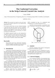
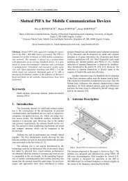
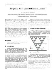
Fig. 1. Current mode square-root circuit block diagram.<br />
Second order SRD all-pass filter can be realized using<br />
(9). According to (9) the proposed all-pass filter is designed<br />
by using square-root blocks, current mirrors, current<br />
sources and grounded capacitors. In these equations, each<br />
square-root term can be designed using a square-root block<br />
diagram with two input currents shown as in Fig. 1.<br />
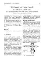
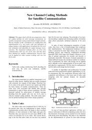
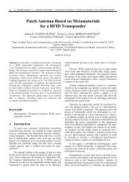
Block diagram in Fig. 1 is realized by using MOS<br />
transistors as shown in Fig. 2 [26]. That circuit operates as<br />
a square-root circuit since its output is the square-root of<br />
two input currents I x and I y . This expression is formulated<br />
as shown in (10).<br />
M1'<br />
M2'<br />
M3'<br />
M4'<br />
M5'<br />
VS<br />
I<br />
II . (10)<br />
out x y<br />
M6'<br />
I M7'<br />
x<br />
M9'<br />
M12'<br />
I x I y<br />
I y<br />
M8'<br />
M10'<br />
M11'<br />
M13' M14' M15' M16'<br />
Fig. 2. Current mode square-root circuit derived from [26].<br />
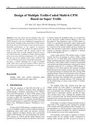
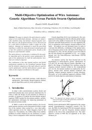
In this paper the proposed second order SRD all-pass<br />
filter circuit is designed as seen in Fig. 3.<br />
3. Simulation Results<br />
The second order all-pass filter consists of four<br />
square-root circuit blocks, current mirrors, current sources<br />
and two grounded capacitors. The designed circuit has been<br />
simulated using TSMC 0.35µm CMOS model parameters<br />
in PSpice program. The circuit supply voltage is selected to<br />
be 2.7 V. The values of two capacitances of the circuit are<br />
chosen to be 15 pF. The bias current of circuit I f is set to be<br />
50 µA. Input voltage of the proposed circuit u is set to<br />
0.75 V DC and 50 mV AC values. Added DC voltage u 2 is<br />
set to 1 V. The gain of the filter is chosen as 1 and quality<br />
factor Q is chosen as 5. Dimensions of transistors in the<br />
proposed filter circuit are given in Tab. 2.<br />
Transistor<br />
M1, M4, M8,<br />
M9, M13, M14,<br />
M15, M20, M22<br />
W<br />
(m)<br />
L<br />
(m)<br />
6 0.7<br />
Transistor<br />
M2, M5, M6,<br />
M7,M10,<br />
M11, M21<br />
W<br />
(m)<br />
L<br />
(m)<br />
20 0.7<br />
M12 1.2 0.7 M3 22.4 0.7<br />
M18 2.8 0.7 M16, M17 36 0.7<br />
M19 2.4 0.7 M23 3.6 0.7<br />
M3', M4', M8',<br />
M10', M15', M16'<br />
6 0.7<br />
M1', M2',<br />
M5', M6',<br />
M7', M9'<br />
20 0.7<br />
M13', M14' 3 0.7 M11', M12' 40 0.7<br />
Tab. 2. Dimensions of the MOS transistors for square-root<br />
circuit in Fig. 2 and 3.
182 S. SURAV YILMAZ, A. T. TOLA, R. ARSLANALP, A NOVEL SECOND-ORDER ALL-PASS FILTER USING SQUARE-ROOT …<br />
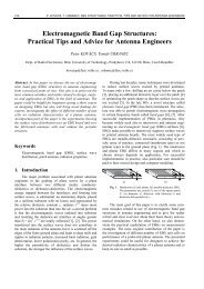
Fig. 3. Proposed second order SRD all-pass filter circuit diagram.<br />
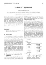
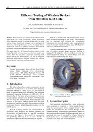
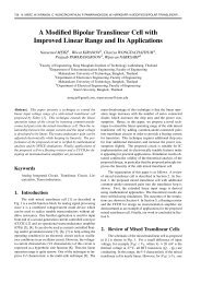
The designed all-pass filter circuit’s pole frequency is<br />
obtained about 1.69 MHz. The filter is analyzed in PSpice<br />
for frequency response. Obtained gain and phase responses<br />
of the filter are shown in Fig. 4.<br />
amplitude values from 10 mV to 100 mV. The obtained<br />
results are plotted in Fig. 7. THD analysis results show<br />
that; when input voltage amplitude is below 10 mV, THD<br />
is less than 0.4 %; THD is below than 4 % for input voltage<br />
amplitude is below 100 mV.<br />
Fig. 4. Second order all-pass filter gain and phase response.<br />
Fig. 5 shows the transient analysis response of the<br />
proposed all-pass filter in Fig. 3 while applying a 50mV<br />
sinusoidal wave with frequency of 1.69 MHz at the input.<br />
Input and output voltages of the proposed filter are given as<br />
in Fig. 5.<br />
Next simulation is performed for frequency response<br />
of the circuit by tuning the pole frequency electronically.<br />
The quality factor of filter is set to Q = 5. The simulations<br />
are performed to tune the pole frequency by varying the<br />
values of the current sources. Varying the values of the<br />
current sources, from 15 µA to 150 µA, the pole frequency<br />
of the filter is tuned. The resulting frequency response for<br />
all-pass filters is plotted in Fig. 6.<br />
Total harmonic distortion values are calculated<br />
through PSpice simulation program for input voltage<br />
Fig. 5. Second order all-pass filter time domain response.<br />
Fig. 6. Electronically tunable second order all-pass filter<br />
phase response.
RADIOENGINEERING, VOL. 22, NO. 1, APRIL 2013 183<br />
Gaussian change in the zero-bias threshold voltage (VTO)<br />
and transconductance coefficient (KP) are applied to all<br />
NMOS and PMOS transistors in the circuit at the same<br />
time. Obtained phase and gain responses of the filter are<br />
given in Fig. 10.<br />
Fig. 7. Total harmonic distortion for various input voltages.<br />
Statistical analysis of the proposed circuit was also<br />
performed by using PSpice program. Simulation results of<br />
Monte-Carlo analysis for 5% Gaussian change in the C 1<br />
and C 2 capacitor values and 10% Gaussian change in the I f<br />
current sources value are given in Fig. 8 and 9 respectively.<br />
Fig. 10. Monte-Carlo analysis for the phase and gain responses<br />
for 0.5% Gaussian change in the process parameters of<br />
all transistors.<br />
In the proposed circuit, MOS transistors’ variation is<br />
also studied by using PSpice program. According to analysis<br />
results, dimensions (W) of all NMOS transistors are<br />
changed 1% in the circuit and the obtained phase and gain<br />
responses are given in Fig. 11.<br />
Fig. 8. Monte-Carlo analysis for the phase and gain responses<br />
for 5% Gaussian change in the C 1 and C 2 capacitor<br />
values.<br />
Fig. 11. Gain and Phase responses when all NMOS transistor<br />
dimensions (W) are changed 1%.<br />
Fig. 9. Monte-Carlo analysis for the phase and gain responses<br />
for 10% Gaussian change in the I f ’s current source<br />
values.<br />
Monte-Carlo analysis is also applied to MOS transistor<br />
process parameters. According to this simulation 0.5%<br />
Noise analysis of the proposed circuit is performed<br />
for Q = 5. Obtained output noise performance is given in<br />
Fig. 12. Also the proposed filter’s total power dissipation is<br />
calculated as 9.67 mW.<br />
The proposed second order all-pass filter is operated<br />
for different quality factor, by changing dimensions of<br />
transistors M3, M12, M13, M16, M17, M18, M19 and<br />
M23. Dimensions of those are given in Tab. 3 for different<br />
quality factors between 3 and 10. The filter is analyzed in<br />
PSpice for pole frequency of 3.9 MHz. Obtained phase<br />
responses are given in Fig. 13.
184 S. SURAV YILMAZ, A. T. TOLA, R. ARSLANALP, A NOVEL SECOND-ORDER ALL-PASS FILTER USING SQUARE-ROOT …<br />
Fig. 12. Output noise of second order all-pass filter.<br />
Fig. 13. Phase response of Fig. 3 for different quality factors.<br />
Quality Factor<br />
Transistor<br />
Q= 3 Q = 5 Q = 7 Q = 10<br />
W(µm) L(µm) W(µm) L(µm) W(µm) L(µm) W(µm) L(µm)<br />
M3 22.2 0.7 22.4 0.7 22 0.7 21.6 0.7<br />
M12 2 0.7 1.2 0.7 1.7 0.7 1.2 0.7<br />
M13 6 0.7 6 0.7 12 0.7 12 0.7<br />
M16 36 0.7 36 0.7 36 0.7 70 0.7<br />
M17 36 0.7 36 0.7 36 0.7 70 0.7<br />
M18 8 0.7 2.9 0.7 1.5 0.7 1.4 0.7<br />
M19 4 0.7 2.4 0.7 1.7 0.7 1.2 0.7<br />
M23 2 0.7 3.6 0.7 4.3 0.7 4.8 0.7<br />
Tab. 3. Dimensions of the MOS transistors in Fig. 3 for different quality factors.<br />
4. Conclusions<br />
In this paper, a second order SRD all-pass filter<br />
circuit is designed. The proposed filter is synthesized by<br />
using the state-space method and by adopting translinear<br />
circuits. The proposed SRD circuit has following advantages:<br />
(a) Pole frequency of the filter can be changed electronically<br />
by adjusting the values of DC current sources<br />
only. (b) The circuit has canonical number of capacitors<br />
which are grounded. (c) The filter does not suffer from<br />
disadvantages of use of resistors in IC process. (d) The<br />
filter has high quality factor. Only analysis results for Q = 5<br />
are given. It can be operated for different high quality factors<br />
by changing dimension of any transistors. (e) The filter<br />
has high input impedance. The filter is simulated in PSpice<br />
for transient, AC, Monte-Carlo, noise and THD analysis.<br />
Obtained results show that the measured total harmonic<br />
distortions are less than 4% and total power dissipation is<br />
9.67 mW. Obtained results are sufficient for analog integrated<br />
circuit design.<br />
Acknowledgement<br />
This work was supported by Pamukkale University<br />
Scientific Research Projects fund with the project code<br />
2011FBE090.<br />
References<br />
[1] MULDER, J., WOERD, A. C., SERDIJN, W. A., ROERMUND, H.<br />
M. General current-mode analysis method for translinear filters.<br />
IEEE Transactions on Circuits and Systems I: Fundamental Theory<br />
and Applications, 1997, vol. 44, no. 3, p. 193-197.<br />
[2] YU, G. J., LIN, Y. S. Low voltage tunable square-root domain bandpass<br />
filter with translinear loop technique in biomedical engineering.<br />
Life Science Journal-Acta Zhengzhou University Overseas Edition,<br />
2010, vol. 7, no. 1, p. 30-33.<br />
[3] FREY, D. R. Log-domain filtering: an approach to current-mode<br />
filtering. IEE Proceedings-g, 1993, vol. 140, no. 6, p. 406-416.<br />
[4] FREY, D. R. Exponential state space filters: A generic current mode<br />
design strategy. IEEE Transactions on Circuits and Systems I:<br />
Fundamental Theory and Applications, 1996, vol. 43, p. 34-42.<br />
[5] SEEVINCK, E. Companding current mode integrator: A new circuit<br />
principle for continuous-time monolithic filters. Electronics Letters,<br />
1990, vol. 26, no. 24, p. 2046-2047.<br />
[6] ESKIYERLI, M. H., PAYNE, A. J. “Square root domain” filter<br />
design and performance. Analog Integrated Circuits and Signal<br />
Processing, 2000, vol. 22, p. 231-243.<br />
[7] ESKIYERLI, M. H., PAYNE, A. J., TOUMAZOU, C. State-space
RADIOENGINEERING, VOL. 22, NO. 1, APRIL 2013 185<br />
synthesis of biquads based on the MOSFET square law. In IEEE<br />
International Symposium on Circuits and Systems, 1996, vol. 1,<br />
p. 321-324.<br />
[8] LOPEZ-MARTIN, A., CARLOSENA, A. Systematic design of<br />
companding systems by component substitution. Analog Integrated<br />
Circuits and Signal Processing, 2001, vol. 28, no. 1, p. 91 to 106.<br />
[9] PSYCHALINOS, C., VLASSIS, S. A systematic design procedure<br />
for square-root domain circuits based on the signal flow graph<br />
approach. IEEE Transactions on Circuits and Systems, 2002,<br />
vol. 49, no. 12, p. 1702–1712.<br />
[10] OLMEZ, S., CAM, U. A novel square-root domain realization of<br />
first order all-pass filter. Turkish Journal of Electrical Engineering<br />
and Computer Sciences, 2010, vol. 18, no. 1, p. 141-146.<br />
[11] CAKIR, C., CAM, U., CICEKOGLU, O. Novel allpass filter<br />
configuration employing single OTRA. IEEE Trans. Circuits Syst.<br />
II, Analog Digit. Signal Process., 2005, vol. 52, no. 3, p. 122 -125.<br />
[12] MAHESHWARI, S., KHAN, I. A. Simple first-order translinear-C<br />
current mode all pass filter section. International Journal of<br />
Electronic, 2003, vol. 90, p. 79-85.<br />
[13] TOLA, A. T., ARSLANALP, R., SURAV YILMAZ, S. Current<br />
mode high-frequency KHN filter employing differential class AB<br />
log domain integrator. International Journal of Electronics and<br />
Communications (AEÜ), 2009, vol. 63, p. 600-608.<br />
[14] YUCE, E., PAL, K., MINAEI, S. A high input impedance voltagemode<br />
all-pass/notch filter using a single variable gain current<br />
conveyor. Journal of Circuits, Systems, and Computers (JCSC),<br />
2008, vol. 17, no. 5, p. 827-834.<br />
[15] SALAWU, R. I. Realization of an all-pass transfer function using<br />
the second-generation current conveyor. In Proc. Inst. Elect,<br />
Electron. Engrs, 1980, vol. 68, no. 1, p. 183–184.<br />
[16] METIN, B., CICEKOGLU, O. Component reduced all-pass filter<br />
with a grounded capacitor and high-impedance input. Internaional<br />
Journal of Electronics, 2009, vol. 96, p. 445-455.<br />
[17] KESKIN, A. Ü., PAL, K., HANCIOGLU, E. Resistorless first-order<br />
all-pass filter with electronic tuning. International Journal of<br />
Electronics and Communications (AEÜ), 2008, vol. 62, p. 304 to<br />
306.<br />
[18] BIOLEK, D., BIOLKOVA, V. First-order voltage-mode all-pass<br />
filter employing one active element and one grounded capacitor.<br />
Analog Integrated Circuit Signal Processing, 2010, vol. 65, p. 123<br />
to 129.<br />
[19] BHUSAN, M., NEWCOMB, R. W. Grounding of capacitors in<br />
integrated circuits. Electronic Letters, 1967, vol. 3, p. 148–149.<br />
[20] LAHIRI, A., CHOWDHURY, A. A novel first-order current-mode<br />
all-pass filter using CDTA. <strong>Radioengineering</strong>, 2009, vol. 18, no. 3,<br />
p. 300-305.<br />
[21] HERENCSAR, N., KOTON, J., VRBA, K., METIN, B. Novel<br />
voltage conveyor with electronic tuning and is application to<br />
resistorless all-pass filter. In The 34th International Conference on<br />
Telecommunications and Signal Processing (TSP). Budapest<br />
(Hungary), 2011, p. 265-268.<br />
[22] FREY, D. R. State-space synthesis and analysis of log-domain<br />
filters. IEEE Transactions on Circuits and Systems II: Analog and<br />
Digital Signal Processing, 1998, vol. 45, no. 9, p. 1205-1211.<br />
[23] ARSLANALP, R., TOLA, A. T. Electronically tunable square-root<br />
domain filter circuit. In IEEE 15th Signal Processing and<br />
Communications Applications Conference. Eskisehir (Turkey),<br />
2007.<br />
[24] ARSLANALP, R., TOLA, A. T. State space representation for log<br />
domain filtering synthesis. Indian Journal of Pure & Applied<br />
Physics, 2009, vol. 47, p. 745-752.<br />
[25] ARSLANALP, R., TOLA, A. T. ELIN Filtrelerin Genel Sentez<br />
Teorisi ve Gerçeklenme Şartları’. Pamukkale University Journal of<br />
Engineering Science, 2007, vol. 13, no.1, p. 47-56.<br />
[26] YU, G. J., HUANG, C. Y., LIU, B. D., CHEN, J. J. Design of<br />
square-root domain filters. Analog Integrated Circuits and Signal<br />
Processing, 2005, vol. 43, p. 49–59.<br />
About Authors ...<br />
Saziye SURAV YILMAZ was born in Izmir, Turkey, in<br />
1981. She received the B.Sc. and M.Sc. degrees in Electrical<br />
and Electronics Engineering from Pamukkale University,<br />
Denizli, Turkey in 2001 and 2005, respectively. She<br />
has been working as a Research Assistant at Pamukkale<br />
University, Denizli, Turkey. Her main research interest<br />
include square-root domain filtering, log domain filtering,<br />
electronic circuit design, and nonlinear circuit and system<br />
theory.<br />
Abdullah T. TOLA was born in Ankara, Turkey, in 1967.<br />
He received the B.S. and M.S. degrees in Electrical and<br />
Electronics Engineering from Dokuz Eylul University,<br />
Izmir, Turkey and Ph.D. degree in Electrical Engineering<br />
from Lehigh University, PA, USA in 1989, 1993, and<br />
2000, respectively. He has been working as an Associate<br />
Professor at Pamukkale University. His main research<br />
interests include log domain filtering, square-root domain<br />
filtering, differential type Class AB filters, electronic circuit<br />
design, nonlinear circuit and system theory, analog<br />
filters, and database systems.<br />
Remzi ARSLANALP was born in Manisa, Turkey, in<br />
1977. He received the B.S., M.S. and Ph.D. degrees in<br />
Electrical and Electronics Engineering from Pamukkale<br />
University, Denizli, Turkey in 1999, 2003, and 2011, respectively.<br />
He has been working as an Assistant Professor<br />
at Pamukkale University since 2011. His main research<br />
interests include log domain filtering, circuit design, and<br />
nonlinear circuit and system theory.