full-text - Radioengineering
full-text - Radioengineering
full-text - Radioengineering

Create successful ePaper yourself
Turn your PDF publications into a flip-book with our unique Google optimized e-Paper software.
414 P. KOVÁCS, T. URBANEC, EBG STRUCTURES: PRACTICAL TIPS AND ADVICE FOR ANTENNA ENGINEERS<br />
Electromagnetic Band Gap Structures:<br />
Practical Tips and Advice for Antenna Engineers<br />
Peter KOVÁCS, Tomáš URBANEC<br />
Dept. of Radio Electronics, Brno University of Technology, Purkyňova 118, 612 00, Brno, Czech Republic<br />
kovacsp@feec.vutbr.cz, urbanec@feec.vutbr.cz<br />
Abstract. In this paper we discuss the use of electromagnetic<br />
band gap (EBG) structures in antenna engineering<br />
from a practical point of view. Our aim is to point out the<br />
most common mistakes and myths related to design, analysis<br />
and application of EBGs in the field of antennas. The<br />
paper could be helpful for beginners giving a short course<br />
on designing EBGs but also will bring novel findings for<br />
experts, investigating the effect of different number of unit<br />
cells on radiation characteristics of a planar antenna.<br />
An important part of the paper is the experiments showing<br />
the surface wave distribution over an EBG board and over<br />
the fabricated antennas with and without the periodic<br />
structure.<br />
Keywords<br />
Electromagnetic band gap (EBG), surface wave<br />
distribution, patch antenna, radiation properties.<br />
1. Introduction<br />
The major problem associated with planar antennas<br />
originates in the guiding of plane waves by a plane<br />
interface between two different media: conductordielectrics<br />
or dielectrics-dielectrics. The electromagnetic<br />
energy trapped between the interfaces, and forming into<br />
surface waves, is substantial: an elementary dipole, placed<br />
on a uniform substrate with no losses and represented by<br />
the relative dielectric constant ε, radiates ε 3/2 times more<br />
power into the substrate than into the air; a second problem<br />
is that the electromagnetic waves radiated into substrate<br />
and reaching the dielectric-air interface at angles greater<br />
than θ c = sin -1 ε -1/2 are totally reflected [1], [2]. The power<br />
transferred into the surface waves does not contribute to<br />
the main radiation of the antenna, but it is scattered off the<br />
edges of the finite ground plane and leads to deep nulls and<br />
ripples in radiation patterns, increased back radiation, gain<br />
deterioration, lower polarization purity, etc. In general, the<br />
higher the permittivity of dielectrics and thicker the<br />
substrate, the stronger the influence of the surface waves.<br />
During last decades, many techniques were developed<br />
to reduce surface waves excited by printed antennas.<br />
To name only a few: drilling an air cavity below the patch<br />
[3], placing an additional dielectric layer over the patch [4]<br />
or optimizing the patch shape so that the surface waves are<br />
not excited [5]. In the late 80's, a novel structure called<br />
photonic band gap (PBG) has been introduced. The structure<br />
was able to permit electromagnetic wave propagation<br />
in certain frequency bands called band gaps [6], [7]. After<br />
successful implementation of PBGs in photonics, they<br />
became widely used also in microwave and antenna engineering<br />
as electromagnetic band gap (EBG) surfaces [8].<br />
EBGs make possible to intensively suppress surface waves<br />
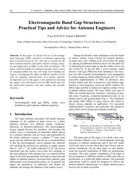
in printed antenna boards. The most widely used type of<br />
EBGs are metallo-dielectric structures, consisting of periodic<br />
array of patches, connected (mushroom type) or not<br />
(planar type) to the ground plane (Fig. 1). The mushroom<br />
and planar EBG differs in many aspects and which to<br />
choose always depends on application. For successful<br />
implementation in practice, also particular care should be<br />
paid to their correct design and computer modeling.<br />
a) b)<br />
Fig. 1. Mushroom (a) and planar (b) metallo-dielectric EBG.<br />
The parameters are: period D, size of the square patch<br />
P, via diameter d, dielectric slab thickness h and<br />
dielectric slab permittivity ε.<br />
The main goal of this paper is to clarify some common<br />
mistakes related to use of electromagnetic band gap<br />
structures in antenna engineering and to give the reader<br />
a brief and clear overview about their basic theory and numerical<br />
simulations. On the other hand, we also demonstrate<br />
the practical exploitation of EBGs on measurement<br />
examples. The most original contribution of the paper is<br />
the investigation of different number of EBG unit cells on<br />
performance of a probe-fed planar antenna. The presented<br />
experiments could be useful for designers to achieve the<br />
desired radiation characteristics of a planar antenna and to<br />
keep its size as small as possible.
RADIOENGINEERING, VOL. 21, NO. 1, APRIL 2012 415<br />
2. Theory<br />
2.1 Mushroom or Planar EBG?<br />
Let us investigate the prerequisites for transverse<br />
magnetic (TM) and transverse electric (TE) surface wave<br />
propagation on a general impedance surface whose properties<br />
can be described with a single parameter, the surface<br />
impedance Z s [1], [8]. The surface is positioned in the y-z<br />
plane as shown in Fig. 2. A surface wave propagates in the<br />
+z direction with the fields decaying exponentially with<br />
decay constant α in the +x direction.<br />
Fig. 3. Surface wave dispersion diagram of a metal-backed<br />
dielectric slab.<br />
Fig. 2. A surface wave on an impedance surface.<br />
For TM surface waves, the x and z components of the<br />
magnetic field intensity and the y component of the electric<br />
field intensity are equal to zero, H x = H z = E y = 0. The<br />
surface wave impedance can be expressed as the ratio of<br />
the electric field over the magnetic field at the surface [1],<br />
[8]<br />
Ez<br />
j <br />
Z sTM<br />
<br />
. (1)<br />
H <br />
In accordance with (1), where ε eff is the effective<br />
permittivity, TM surface waves can occur on surfaces with<br />
a positive (i.e. inductive) reactance only, and thus, ε eff must<br />
be positive too. For TE waves, E x = E z = H y = 0 and the<br />
surface impedance can be derived [1], [8]<br />
Ey<br />
j <br />
<br />
Z <br />
eff<br />
s TE . (2)<br />
H <br />
z<br />
Taking (2) into account, where μ eff is the effective permeability,<br />
TE waves require the negative (i.e. capacitive)<br />
surface impedance, and thus, μ eff must be positive, too.<br />
A typical dispersion relation of TM and TE surface<br />
waves on a metal-backed dielectric slab is depicted in<br />
Fig. 3. Obviously, the surface guides TM wave from zero<br />
frequency (the surface impedance is inductive). At the<br />
frequency for which the dielectric slab thickness equals<br />
approximately one-quarter wavelength, the surface impedance<br />
becomes capacitive and the first TE wave occurs.<br />
However, the TM is still propagating: the wave simply<br />
adjusts its position toward the ground plane and the apparent<br />
surface impedance remains inductive [1], [8]. This fact<br />
is illustrated in Fig. 4, where the normalized magnetic field<br />
intensity of surface waves inside and above a metal-backed<br />
slab (thickness h = 1.575 mm and relative permittivity<br />
ε = 6.15) for different frequencies is shown. In consequence,<br />
exceeding cutoff frequency of the first TE mode,<br />
a surface-wave free dielectric slab can be achieved only by<br />
simultaneous suppression of both TM and TE polarized<br />
waves.<br />
y<br />
eff<br />
Fig. 4. Normalized magnetic field intensity of TM surface<br />
wave inside and above of a metal-backed dielectric<br />
slab (h = 1.575 mm, ε = 6.15).<br />
Now, how to create a media with negative permittivity<br />
and/or permeability? Let us investigate the equivalent<br />
circuit representation (L-C network) of a metallo-dielectric<br />
EBG unit cell (Fig. 5). If the size of the unit cell (i.e. period<br />
of the structure D) is considerably smaller than the wavelength<br />
λ, the effective permittivity ε eff and effective permeability<br />
μ eff of the periodic media can be expressed using the<br />
series impedance Z and shunt admittance Y as [9]<br />
and<br />
Y<br />
<br />
, (3)<br />
eff<br />
j <br />
D<br />
0<br />
Z<br />
. (4)<br />
eff<br />
j <br />
D<br />
0<br />
In (3) and (4) ε 0 and μ 0 are the permittivity and permeability<br />
of free space, respectively. According to selection of L<br />
and C elements as the series and shunt components of the<br />
unit cell, four types of materials with different properties<br />
(positive/negative permittivity/permeability) can be created<br />
as listed in Tab. 1.<br />
Fig. 5. Equivalent network model of a metallo-dielectric EBG.
416 P. KOVÁCS, T. URBANEC, EBG STRUCTURES: PRACTICAL TIPS AND ADVICE FOR ANTENNA ENGINEERS<br />
ε eff μ eff Series<br />
L<br />
Series<br />
C<br />
Shunt<br />
L<br />
Shunt<br />
C<br />
+ + Yes No No Yes<br />
± + Yes No Yes Yes<br />
+ ± Yes Yes No Yes<br />
± ± Yes Yes Yes Yes<br />
Tab. 1. Four categories of metallo-dielectric EBGs.<br />
Considering that the essential difference between<br />
mushroom and planar EBGs (Fig. 1) is the presence or<br />
absence of shorting vias which represent a shunt inductance<br />
in the equivalent network model, the following conclusion<br />
can be made: the mushroom EBG can suppress<br />
surface waves of both polarization (both permittivity and<br />
permeability can be negative), whereas the planar one can<br />
suppress TE waves only (permeability can be negative).<br />
However, even the mushroom EBG cannot suppress TM and<br />
TE surface waves at the same time – a medium with negative<br />
permittivity and permeability supports so-called backwardwave<br />
propagation [8], [10].<br />
Based on the above stated, surface waves can be<br />
success<strong>full</strong>y suppressed by EBGs, if the following rules are<br />
kept:<br />
the antenna (exciting surface waves of both<br />
polarization) works under the first substrate TE<br />
surface wave cutoff frequency (i.e. the slab guides<br />
TM 0 mode only),<br />
a mushroom-type EBG is used.<br />
If these conditions are not satisfied, the suppression<br />
of surface waves is impossible and there is only a minor (if<br />
any) improvement in radiation properties of an antenna<br />
surrounded by EBG cells. For example, the well-known<br />
uniplanar compact electromagnetic band-gap (UC-EBG)<br />
structure will never work in combination with an antenna<br />
that excites both TM and TE surface waves, because of the<br />
absence of vias. This fact can be clearly recognized e.g. in<br />
[11], [12].<br />
For the sake of clarity, it is necessary to emphasize,<br />
that the above described equivalent network representation<br />
of metallo-dielectric EBGs and its resonant behavior,<br />
which leads to negative permittivity/permeability of the<br />
periodic medium, is valid only if the period of the structure<br />
is significantly smaller than the wavelength. When the<br />
period becomes comparable to the wavelength, typically<br />
D ≈ n(λ/2), n = 1, 2, 3..., periodic structures generate<br />
a series of stop bands. However, this phenomenon is then<br />
not related to the described unit cell resonance effect, but<br />
to Bragg's diffraction condition.<br />
2.2 Numerical Modeling of EBGs<br />
Let us consider a plane wave impinging on a periodic<br />
surface. For surface waves, the angle of incidence is equal<br />
to 90° (parallel with the surface). For this value, the wave<br />
propagation on a periodic structure cannot be investigated<br />
using the plane wave response [13]. The exact position of<br />
pass bands and band gaps in the frequency spectrum can be<br />
obtained only by the dispersion relation of surface waves<br />
(i.e. calculating the resonant frequencies of eigenmodes)<br />
along the contour of the irreducible Brillouin zone.<br />
For correct EBG design, it is essential to distinguish<br />
between reflection- and dispersion response of a structure.<br />
As described in many papers, the frequency of zero reflection<br />
phase (usually calculated for normal wave incidence)<br />
does not necessarily lie inside the surface wave band gap.<br />
These two properties of EBGs crucially depend on parameters<br />
of the dielectric substrate (thickness and permittivity)<br />
and drift with variation of them [14], [15], [16].<br />
Analysis of electromagnetic band gap structures is<br />
based on the Bloch-Floquet theorem which describes the<br />
wave propagation in infinite media consisting of periodic<br />
repetition of a unit cell. The theorem states, the properties<br />
of wave propagation in a periodic media can be <strong>full</strong>y described<br />
considering only one unit cell and applying periodic<br />
boundary conditions at its edges [17].<br />
Fig. 6. Numerical model of a mushroom-type EBG unit cell in<br />
CST MWS for dispersion diagram calculation.<br />
Nowadays, many commercial softwares are able to<br />
calculate the dispersion relation of a periodic structure<br />
using the eigenmode solver of the tool. However, the<br />
proper unit cell setup, thus, the correct surface wave<br />
diagram calculation, is another crucial point in the design<br />
of EBGs. The eigenmode solver of some tools (e.g. CST<br />
Microwave Studio, CST MWS) does not support open<br />
boundaries. In this case, the boundary condition of side<br />
walls of the unit cell can be considered periodic, but the<br />
boundaries at the top and the bottom of the model should<br />
be defined as electric conductor, see Fig. 6. The key<br />
parameter in the computer model is then the height of the<br />
air column h a placed above the dielectric substrate to<br />
emulate the free space over the structure. Considering that<br />
surface waves are mainly concentrated inside the substrate<br />
and at the substrate/air interface, a relatively small height<br />
of the air column could be sufficient. Based on numerous<br />
computer simulations and by comparing the obtained<br />
results with analytical and experimental considerations, the<br />
correct choice of approximately ten times the substrate<br />
thickness was established, 10 h .<br />
h a
RADIOENGINEERING, VOL. 21, NO. 1, APRIL 2012 417<br />
3. Experiments<br />
3.1 Design of an EBG<br />
To design electromagnetic band gap structures, numerous<br />
approximate and analytical methods were worked<br />
out [8], [18]. Nevertheless, only <strong>full</strong>-wave techniques offer<br />
an exact approach. Moreover, due to complex behavior of<br />
EBGs, stochastic methods can be success<strong>full</strong>y exploited.<br />
A combination of a <strong>full</strong>-wave numerical tool (CST MWS)<br />
with a global optimization algorithm (particle swarm optimization,<br />
PSO) was introduced in [19]. The developed<br />
technique is based on <strong>full</strong>-wave characterization of EBGs<br />
and optimization of parameters of the unit cell to fulfill the<br />
requirements. The approach is versatile and robust, applicable<br />
not only for final tuning, but also for rough initial<br />
design.<br />
Using the CST MWS – PSO combination, a mushroom<br />
EBG was designed with surface-wave band gap at<br />
f = 10 GHz. The structure is realized on Arlon AD600 with<br />
thickness h = 1.575 mm and relative permittivity ε = 6.15.<br />
At the working frequency the substrate guides only the<br />
basic TM 0 surface mode (the TE 1 mode begins to propagate<br />
at f = 21 GHz). Optimized parameters of the unit cell<br />
are: D = 2.22 mm, P = 2.04 mm and d = 0.40 mm.<br />
A board consisting 100 x 100 unit cells was fabricated<br />
and measured. The experimental setup is depicted in<br />
Fig. 7 and it was inspired by the one presented in [20].<br />
The TM surface wave propagation above the fabricated<br />
EBG and a conventional metal-backed slab made<br />
from the same dielectrics as the EBG was investigated.<br />
A small probe recording the electric field strength over the<br />
test board was used and surface-wave maps in horizontal<br />
and vertical cuts were created (the resolution is 0.25 mm in<br />
all directions). Fig. 8 shows surface wave propagation in<br />
a vertical cut over the two surfaces under investigation.<br />
The frequency was chosen f = 10 GHz, where the designed<br />
EBG has its band gap and strongly attenuates the propagation<br />
of TM waves. This fact is also confirmed in Fig. 9<br />
where the TM wave attenuation in dependence on number<br />
of unit cells is shown (the field strength was recorded<br />
1 mm above the surface). Apparently, the field intensity<br />
decreases rapidly for the first five unit cells; the impact of<br />
the rest of cells is almost negligible. Based on this fact, the<br />
effect of different number of EBG unit cells on planar<br />
antenna performance is examined in the next chapter. The<br />
main goal is to establish the basic design rules for sufficient<br />
surface waves suppression and to keep the dimensions<br />
of the antennas as small as possible.<br />
a)<br />
b)<br />
Fig. 8. Measured TM surface wave propagation at f = 10 GHz,<br />
x-z cut: (a) conventional metal-backed dielectric<br />
substrate, (b) EBG board. Normalized electric field<br />
intensity is shown.<br />
Fig. 7. Experimental setup for TM surface wave propagation<br />
measurement.<br />
Fig. 9. Measured TM surface wave attenuation at f = 10 GHz<br />
along the x-axis, 1 mm over the surface.<br />
3.2 EBG Planar Antennas<br />
Using the mushroom structure introduced in the previous<br />
section, six coaxial probe fed planar antennas were<br />
designed, fabricated and measured at f = 10 GHz. The<br />
antennas were realized in three dimensions and two variants:<br />
without EBG and with EBG. For schematic view see
418 P. KOVÁCS, T. URBANEC, EBG STRUCTURES: PRACTICAL TIPS AND ADVICE FOR ANTENNA ENGINEERS<br />
Fig. 10. Parameters of the antenna patch are: A = 4.80 mm,<br />
B = 4.30 mm, C = 0.80 mm (antennas without EBG) and<br />
A = 5.30 mm, B = 4.50 mm, C = 1.10 mm (antennas with<br />
EBG). The space S between the patch and the surrounding<br />
EBG is crucial in terms of impedance matching and radiation<br />
properties (shape of radiation pattern and gain) of<br />
an antenna: if S is too small, the coupling between the<br />
radiating patch and the EBG cells is too large – the antenna<br />
cannot be tuned; on the other hand, by increasing S, the<br />
effect of the EBG on antenna radiation properties decreases<br />
rapidly. This phenomenon is partially described in the<br />
literature, e.g. [21], but there is no particular recommendation<br />
for the correct choice of S. Considering a plane wave<br />
impinging on the designed mushroom surface at angle near<br />
to 90° (almost surface wave), the reflection phase response<br />
of the structure approximately 0° is obtained. The interference<br />
between the direct waves radiated by the patch and<br />
the waves reflected from the EBG is then constructive if<br />
the gap between the patch and the EBG is approximately<br />
half of the wavelength, S ≈ λ/2, where λ can be estimated<br />
using the simple equation<br />
c<br />
. (5)<br />
1<br />
f <br />
2<br />
In (5), c is the light velocity in free space, f is the frequency<br />
and ε is the relative permittivity of the dielectrics. In our<br />
case λ ≈ 16 mm, thus S ≈ 8 mm. Computer simulations<br />
have shown, the EBG antennas can be matched if S ≥ 3D,<br />
i.e. S ≥ 6.66 mm. Then, the overall size of the antennas can<br />
be determined as<br />
2<br />
n 1<br />
D 5<br />
n<br />
D<br />
L 2 S <br />
2<br />
(6)<br />
where n is the number of EBG columns surrounding the<br />
antenna patch. For n = 3, 6 and 9: L = 24.42 mm (antenna<br />
#1), L = 37.74 mm (antenna #2) and L = 51.06 mm<br />
(antenna #3), respectively.<br />
a) b)<br />
Fig. 10. Schematic of coaxial probe fed planar antenna without<br />
EBG (a), with EBG (b). Top (x-y) view.<br />
The measured reflection coefficient is shown in<br />
Fig. 11. Obviously, coupling between the antenna patch<br />
and the EBG is significant and produces parasitic<br />
resonances at the lower limit of the band gap (around<br />
f = 9 GHz). However, at the working frequency f = 10 GHz<br />
all the antennas are matched and the reflection coefficient<br />
is lower than –10 dB. Ripples on S 11 curves are caused by<br />
imperfect calibration due to the use of 2.4 mm calibration<br />
set and measurement on 3.5 mm connector.<br />
a)<br />
b)<br />
Fig. 11. Measured reflection coefficient of the antennas:<br />
without EBG (a), with EBG (b).<br />
Next, the electric field distribution 1 mm above the<br />
antennas was measured using the scanning device. As seen<br />
in Fig. 12 – Fig. 14, where the dashed line denotes the<br />
boundaries of the slab, the field strength rapidly decreases<br />
from the centre of the structure and just a small amount of<br />
energy, distributed by surface waves, reaches the boundary<br />
of the dielectric substrate if the EBG is used. This effect is<br />
apparent even for 3 columns of EBG unit cells surrounding<br />
the antenna patch.<br />
Also radiation properties of the antennas were investigated<br />
and measured co-polar and cross-polar directivity<br />
patterns are shown in Fig. 15 – Fig. 17. For easier comparison<br />
between the antennas, the most relevant parameters are<br />
summarized in Tab. 2. In this table, the front-to-back ratio<br />
(FBR) is defined as the difference between the maximum<br />
energy emitted in the forward direction between ±30° versus<br />
the maximum energy emitted in the backward direction<br />
between ±150°. The cross-polarization level (XPL) is calculated<br />
for the forward direction between ±30°. The gain<br />
improvement (ΔG) is assumed as the difference between<br />
the maximum power radiated at 0° by the antenna without<br />
EBG versus the antenna with EBG. Efficiency η of the<br />
antennas was computed using CST MWS.
RADIOENGINEERING, VOL. 21, NO. 1, APRIL 2012 419<br />
a) b)<br />
Fig. 12. Normalized electric field distribution over the antenna #1: without EBG (a), with EBG (b).<br />
a) b)<br />
Fig. 13. Normalized electric field distribution over the antenna #2: without EBG (a), with EBG (b).<br />
a) b)<br />
Fig. 14. Normalized electric field distribution over the antenna #3: without EBG (a), with EBG (b).<br />
a) b) c) d)<br />
Fig. 15. Radiation pattern of the antenna #1: without EBG, E-field (a), without EBG, H-field (b), with EBG, E-field (c), with EBG, H-field (d).<br />
Red color: co-polarization, blue color: cross-polarization.
420 P. KOVÁCS, T. URBANEC, EBG STRUCTURES: PRACTICAL TIPS AND ADVICE FOR ANTENNA ENGINEERS<br />
a) b) c) d)<br />
Fig. 16. Radiation pattern of the antenna #2: without EBG, E-field (a), without EBG, H-field (b), with EBG, E-field (c), with EBG, H-field (d).<br />
Red color: co-polarization, blue color: cross-polarization.<br />
a) b) c) d)<br />
Fig. 17. Radiation pattern of the antenna #3: without EBG, E-field (a), without EBG, H-field (b), with EBG, E-field (c), with EBG, H-field (d).<br />
Red color: co-polarization, blue color: cross-polarization.<br />
Antenna #1 Antenna #2 Antenna #3<br />
W/O EBG With EBG W/O EBG With EBG W/O EBG With EBG<br />
Plane E H E H E H E H E H E H<br />
FBR [dB] 16.1 16.6 23.5 21.6 11.6 7.7 20.9 21.1 10.2 9.3 23.3 24.7<br />
XPL [dB] -20.8 -16.3 -23.2 -18.9 -25.2 -13.7 -18.0 -20.1 -28.5 -15.6 -30.3 -26.3<br />
ΔG [dB] – 2.1 – 5.3 – 5.4<br />
η [%] 95.9 99.2 96.6 99.5 96.9 99.6<br />
Tab. 2. Radiation properties of the fabricated antennas without and with EBG.<br />
The general conclusions are the following: The<br />
antennas with EBG in comparison with their counterparts<br />
without EBG have smooth and almost symmetric radiation<br />
patterns, significantly better front-to-back ratio and lower<br />
cross-polarization level. Performance of EBG antennas<br />
with different number of unit cells, vary in a relatively<br />
small way: the major difference is apparent in the antenna<br />
gain, which is also the consequence of smaller or larger<br />
aperture size. The benefit of EBG antennas in comparison<br />
with conventional ones is unambiguous. The number of<br />
unit cells to be chosen always depends on requirements and<br />
maximum allowed dimensions.<br />
4. Conclusions<br />
More than two decades after they have been introduced,<br />
electromagnetic band gap structures still play<br />
important role in microwave and antenna engineering. Following<br />
contemporary trends, microwave devices and antennas<br />
are moving to millimeter-wave and submillimeterwave<br />
frequency bands. Besides numerous advantages of<br />
the new radio spectra, engineers are forced to challenge<br />
new difficulties. For example, antenna designers are facing<br />
to significant losses appearing in planar antennas, especially<br />
in antenna arrays, resulting in decreased antenna gain<br />
and thus, larger structure. Moreover, most of the energy<br />
emitted by an antenna is formed into surface waves and<br />
leads to distorted radiation pattern and very poor front-to<br />
back ratio. EBGs represent a promising way to overcome<br />
some of these problems and to make possible to design e.g.<br />
high-gain, compact antenna arrays with the desired radiation<br />
properties in a relatively simple way. The key to the<br />
success is the correct implementation of EBGs. Unfortunately,<br />
there are some common mistakes and misunderstandings<br />
related to theory, design and practical application<br />
of electromagnetic band gap surfaces in antennas technology.<br />
Our aim was to give a clear and simple explanation<br />
about the basics of metallo-dielectric EBGs and to demonstrate<br />
their practical exploitation on practical examples.<br />
The most original part of the work is the investigation of<br />
different number of EBG unit cells on planar antenna<br />
radiation properties. The presented results could be helpful<br />
for designers to achieve the desired antenna performance<br />
for minimum structure dimensions.
RADIOENGINEERING, VOL. 21, NO. 1, APRIL 2012 421<br />
Acknowledgements<br />
The research leading to these results has received<br />
funding from the European Community's Seventh Framework<br />
Programme (FP7/2007-2013) under grant agreement<br />
no. 230126. The research described in this contribution<br />
was performed in the laboratories supported by the SIX<br />
project; the registration number CZ.1.05/2.1.00/03.0072,<br />
the operational program Research and Development for<br />
Innovation.<br />
References<br />
[1] COLLIN, R. Field Theory of Guided Waves. 2 nd edition. IEEE<br />
Press, New York, 1991.<br />
[2] BROWN, E. R., PARKER, C. D., YABLONOVITCH, E.<br />
Radiation properties of a planar antenna on a photonic-crystal<br />
substrate. J. Opt. Soc. Am. B, 1993, vol. 10, no. 2, p. 404-407.<br />
[3] YOOK, J.-G., KATEHI, L. Micromachined microstrip patch<br />
antenna with controlled mutual coupling and surface waves. IEEE<br />
Transactions on Antennas and Propagation, 2001, vol. 49, no. 9,<br />
p. 1282-1289.<br />
[4] ALEXOPOULOS, N. G., JACKSON, D. R. Fundamental<br />
superstrate (cover) effects on printed circuit antennas. IEEE<br />
Transactions on Antennas and Propagation, 1984, vol. 32, no. 8,<br />
p. 807-816.<br />
[5] JACKSON, D. R., WILLIAMS, J. T., BHATTACHARYYA, R.<br />
K., SMITH, R. L., BUCHHEIT, S. J., LONG, S. A. Microstrip<br />
patch designs that do not excite surface waves. IEEE Transactions<br />
on Antennas and Propagation, 1993, vol. 41, no. 8, p. 1026-1037.<br />
[6] YABLONOVITCH, E. Inhibited spontaneous emission in solid<br />
state physics and electronics. Physical Review Letters, 1987,<br />
vol. 58, p. 2059-2062.<br />
[7] JOHN, S. Strong localization of photons in certain disordered<br />
dielectric super lattices. Physical Review Letters, 1987, vol. 58,<br />
p. 2486-2489.<br />
[8] SIEVENPIPER, D. F. High-impedance electromagnetic surfaces.<br />
Ph.D. Thesis, Los Angeles (CA, USA), 1999.<br />
[9] SANADA, A. Planar single- and double negative metamaterial<br />
implementations and applications. URSI, 2005. Available online<br />
at: http://www.ursi.org/Proceedings/ProcGA05/pdf/D02.3%28012<br />
44%29.pdf<br />
[10] STRATTON, J. Electromagnetic Theory. Wiley, 1941.<br />
[11] COCCIOLI, R., YANG, F.-R., MA, K.-P., ITOH, T. Aperturecoupled<br />
patch antenna on UC-PBG substrate. IEEE Transactions<br />
on Microwave Theory and Techniques, 1999, vol. 47, no. 11,<br />
p. 2123-2130.<br />
[12] LAMMINEN, A. E. I., VIMPARI, A. R., SAILY, J., UC-EBG on<br />
LTCC for 60-GHz frequency band antenna applications. IEEE<br />
Transactions on Antennas and Propagation, 2009, vol. 57, no. 10,<br />
p. 2904-2912.<br />
[13] GOUSETTIS, G., FRESEDIS, A. P., VARDAXOGLOU, Y. C.<br />
Tailoring the AMC and EBG characteristics of periodic metallic<br />
arrays printed on grounded dielectric substrate. IEEE Transactions<br />
on Antennas and Propagation, vol. 54, no.1, 2006, p. 82-89.<br />
[14] CLAVIJO, S., DIAZ, R. E., McKINZIE, W. E. Design<br />
methodology for Sievenpiper high impedance surfaces: an artificial<br />
magnetic conductor for positive gain electrically small antennas.<br />
IEEE Transactions on Antennas and Propagation, 2003, vol. 51,<br />
no. 10, p. 2678-2690.<br />
[15] AMINIAN, A., YANG, F., RAHMAT-SAMII, Y. In-phase<br />
reflection and EM wave suppression characteristics of<br />
electromagnetic bandgap ground planes. In Proc. IEEE AP-S Int.<br />
Symp., 2003, vol. 4, p. 430-433.<br />
[16] LI, L., CHEN, Q., YUAN, Q., LIANG, C., SAWAYA, K. Surfacewave<br />
suppression bandgap and plane-wave reflection phase band<br />
of mushroomlike photonic bandgap structures. J. Appl. Phys.,<br />
2008, vol. 103, no. 2, p. 023513-023513-10.<br />
[17] ENOCH, S., TAYEB, G., MAYSTRE, D. Dispersion diagrams of<br />
Bloch modes applied to the design of directive sources. Progress<br />
in Electromagnetics Research series, 2003, vol. 41, p.61-81.<br />
[18] TRETYAKOV, S. Analytical Modeling in Applied Electromagnetics.<br />
Artech House, 2003.<br />
[19] KOVACS, P., RAIDA, Z. Design and optimization of highimpedance<br />
surfaces. International Journal of RF and Microwave<br />
Computer-Aided Engineering, accepted for publication.<br />
[20] MATSUGATANI, K., TANAKA, M., FUKUI, S., KIM, W. H.,<br />
KIM, M. Surface wave distribution over Electromagnetic Bandgap<br />
(EBG) and EBG reflective shield for patch antenna. IEICE Trans.<br />
Electron., 2005, vol. E88-C, no. 12, p. 2341-2349.<br />
[21] ILUZ, Z., SHAVIT, R., BAUER, R. Microstrip antenna phased<br />
array with electromagnetic bandgap substrate. IEEE Transactions<br />
on Antennas and Propagation, 2004, vol. 52, no. 6, p. 1446-1453.<br />
About Authors ...<br />
Peter KOVÁCS was born in Slovakia. He received the<br />
Ph.D. degree from the Faculty of Electrical Engineering<br />
and Communication (FEEC), Brno University of Technology<br />
(BUT), Czech Republic, in 2011. Currently, he is with<br />
the Dept. of Radio Electronics FEEC BUT.<br />
Tomáš URBANEC was born in Třinec, Czech Republic.<br />
He received his M.Sc. from Brno University of Technology<br />
in 2000 and his Ph.D. in 2007. Since 2007, he has<br />
been an assistant at the Dept. of Radio Electronics, BUT.<br />
He is interested in microwave measurement and design.