TO THE POSSIBILITY OF CALCULATION - Radioengineering
TO THE POSSIBILITY OF CALCULATION - Radioengineering
TO THE POSSIBILITY OF CALCULATION - Radioengineering

Create successful ePaper yourself
Turn your PDF publications into a flip-book with our unique Google optimized e-Paper software.
RADIOENGINEERING, VOL. 17, NO. 4, DECEMBER 2008 13<br />
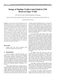
Slotted PIFA for Mobile Communication Devices<br />
Davor BONEFAČIĆ 1 , Bojan RAPINAC 2 , Juraj BAR<strong>TO</strong>LIĆ 1<br />
1 Dept. of Wireless Communications, Faculty of Electrical Engineering and Computing, University of Zagreb,<br />
Unska 3, HR-10000 Zagreb, Croatia<br />
2 Ericsson Nikola Tesla, Mobile Core and Radio Networks, Krapinska 45, HR-10000 Zagreb, Croatia<br />
davor.bonefacic@fer.hr, bojan.rapinac@ericsson.com, juraj.bartolic@fer.hr<br />
Abstract. Slotted PIFA with capacitive loading for operation<br />
in the 880 ÷ 960 MHz band is presented. The PIFA is<br />
intended for mobile terminals in GSM mobile communication<br />
network. The antenna is placed on a ground plane<br />
with dimensions of an average handheld device. It is optimized<br />
by using electromagnetic simulator and a prototype<br />
is manufactured. Calculated and measured results agree<br />
very well. Input impedance matching with SWR < 3 in the<br />
whole band was achieved. Maximum gain of 3.2 dBi is<br />
measured. Preliminary studies of the influence of the user's<br />
head and hand on the antenna characteristics have been<br />
performed.<br />
Keywords<br />
Small antenna, microstrip antenna, planar-inverted-F<br />
antenna, PIFA.<br />
1. Introduction<br />
The increasing interest for small and compact antennas<br />
is the consequence of the development of personal<br />
communications and handheld devices such as organizers,<br />
computers, navigation devices, etc. which are using wireless<br />
access points. For handheld wireless terminals the<br />
antenna is a necessary part. However, due to the market<br />
and end-user requirements, the antenna should not be visible.<br />
The answer to these conflicting requirements are small<br />
and compact antennas which can be integrated in the<br />
device body.<br />
Antenna size and its performance are strongly linked<br />
together. The first fundamental results showing the link<br />
between antenna size and its maximum bandwidth and gain<br />
were presented in the late forties [1, 2].<br />
The antenna size is not mainly determined by the<br />
technology used for its fabrication (like in electronic chips)<br />
but rather by physical laws. Good antenna performances<br />
are obtained when the antenna is resonant and when its size<br />
is comparable to the wavelength. At the operating frequencies<br />
of mobile communications and wireless networks this<br />
means that the antenna should be quite large. Several techniques<br />
and approaches have been introduced to reduce<br />
antenna dimensions and maintain good radiation properties<br />
[3–6]. Research and development on small and compact<br />
antennas is of great importance for all present and future<br />
wireless applications [4], [6]. Most frequently used small<br />
antennas are shorted patches and PIFAs [7–11]. Further<br />
reduction of antenna dimensions is obtained by modifications<br />
introduced in the patch [5], [12], [13]. However, the<br />
reduction in antenna dimensions is always made at the<br />
expense of bandwidth, gain and efficiency.<br />
Another important issue for handheld device antennas<br />
is that these antennas radiate near the human (user's) body.<br />
This interaction should be considered in two ways: how the<br />
human body influences the antenna characteristics (input<br />
impedance, far field radiation pattern, gain and efficiency)<br />
and how the body tissue is affected by the RF energy radiated<br />
by the antenna [14].<br />
2. Antenna Description<br />
y<br />
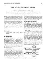
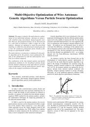
Fig. 1. Slotted PIFA (all dimensions in millimeters).<br />
The antenna proposed in this paper is shown in Fig 1. The<br />
antenna was designed and optimized by using HFSS 3D<br />
full-wave electromagnetic field simulator by Ansoft [15].<br />
The antenna is designed for operation in the 880 to<br />
960 MHz band. Its resonant frequency is chosen roughly at<br />
the center of the frequency operating bandwidth.
14 D. BONEFAČIĆ, B. RAPINAC, J. BAR<strong>TO</strong>LIĆ, SLOTTED PIFA FOR MOBILE COMMUNICATION DEVICES<br />
a)<br />
b)<br />
The antenna is placed on a 50 mm × 100 mm ground<br />
plane at one of the shorter edges. For simulation and<br />
testing purposes the antenna was excited by a coaxial probe<br />
and a SMA connector. However, in a real device, it would<br />
be excited directly from the T/R circuits on the printed<br />
circuit board placed bellow the ground plane. The ground<br />
plane size has been chosen to approximately match the size<br />
of a typical handheld device.<br />
A slot was introduced in the PIFA to increase the path<br />
length of the surface current and reduce the size of the<br />
PIFA. Further length reduction was achieved by bending<br />
the end of the slotted PIFA towards the ground plane. This<br />
increased the capacitive loading at the antenna end. The<br />
introduced modification increased the antenna quality<br />
factor resulting in calculated input impedance bandwidth<br />
(SWR < 3) of only 51 MHz while the capacitive loading<br />
lowered the resonant frequency to 865 MHz. As<br />
satisfactory impedance matching over the design<br />
bandwidth could not be obtained by further modifications<br />
of the bent end of the PIFA, part of the ground plane<br />
bellow the antenna was removed. After this modification,<br />
calculations have shown that the resonant frequency was at<br />
916 MHz, while the input impedance bandwidth was<br />
109 MHz.<br />
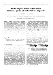
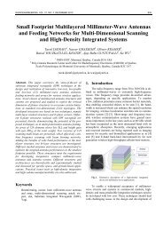
The calculated vector current density on the antenna<br />
at the center of the operating bandwidth (f = 920 MHz) is<br />
shown in Fig. 2. The vector current density has been<br />
calculated for four different moments during the first half<br />
of the signal period T (T = 1 / f). The plots for the second<br />
half of the period are omitted in Fig. 2 because the current<br />
intensity is the same while only the vector directions are<br />
opposite. The current flows around the slot in the PIFA,<br />
which increases the electrical length and allows size<br />
reduction. The current density maximum is at the middle of<br />
the excited part of the PIFA. The current density on the<br />
ground plane is low, but because of the ground plane size<br />
the total current is not negligible and it contributes to<br />
antenna radiation.<br />
c)<br />
d)<br />
Fig. 2. Calculated vector current density on the antenna at f =<br />
920 MHz: a) t=0; b) t=T/8; c) t=T/4; d) t=3T/8; (T = 1 / f).<br />
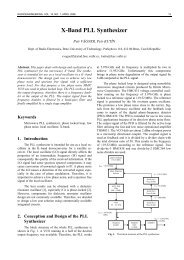
cm<br />
Fig. 3. Slotted PIFA on 50 mm × 100 mm ground plane.<br />
When the simulation and optimization process has been<br />
completed, the antenna prototype was manufactured. The<br />
antenna on the ground plane is shown in Fig. 3. Fig. 4<br />
shows construction details of the prototype.
55<br />
55<br />
55<br />
56<br />
54<br />
56<br />
54<br />
56<br />
54<br />
57<br />
53<br />
57<br />
53<br />
57<br />
53<br />
58<br />
52<br />
58<br />
52<br />
58<br />
52<br />
59<br />
51<br />
59<br />
51<br />
59<br />
51<br />
60<br />
50<br />
60<br />
50<br />
60<br />
50<br />
61<br />
49<br />
61<br />
49<br />
61<br />
49<br />
62<br />
48<br />
62<br />
48<br />
62<br />
48<br />
63<br />
47<br />
63<br />
47<br />
63<br />
47<br />
64<br />
46<br />
64<br />
46<br />
64<br />
46<br />
65<br />
45<br />
65<br />
45<br />
65<br />
45<br />
66<br />
44<br />
66<br />
44<br />
66<br />
44<br />
67<br />
43<br />
67<br />
43<br />
67<br />
43<br />
68<br />
42<br />
68<br />
42<br />
68<br />
42<br />
69<br />
41<br />
69<br />
41<br />
69<br />
41<br />
70<br />
40<br />
70<br />
40<br />
70<br />
40<br />
71<br />
39<br />
71<br />
39<br />
71<br />
39<br />
72<br />
38<br />
72<br />
38<br />
72<br />
38<br />
1<br />
37<br />
1<br />
37<br />
1<br />
37<br />
2<br />
36<br />
2<br />
36<br />
2<br />
36<br />
3<br />
35<br />
3<br />
35<br />
3<br />
35<br />
4<br />
34<br />
4<br />
34<br />
4<br />
34<br />
5<br />
33<br />
5<br />
33<br />
5<br />
33<br />
6<br />
32<br />
6<br />
32<br />
6<br />
32<br />
7<br />
31<br />
7<br />
31<br />
7<br />
31<br />
8<br />
30<br />
8<br />
30<br />
8<br />
30<br />
9<br />
29<br />
9<br />
29<br />
9<br />
29<br />
10<br />
28<br />
10<br />
28<br />
10<br />
28<br />
11<br />
27<br />
11<br />
27<br />
11<br />
27<br />
12<br />
26<br />
12<br />
26<br />
12<br />
26<br />
13<br />
25<br />
13<br />
25<br />
13<br />
25<br />
14<br />
24<br />
14<br />
24<br />
14<br />
24<br />
15<br />
23<br />
15<br />
23<br />
15<br />
23<br />
16<br />
22<br />
16<br />
22<br />
16<br />
22<br />
17<br />
21<br />
17<br />
21<br />
17<br />
21<br />
18<br />
20<br />
18<br />
20<br />
18<br />
20<br />
19<br />
19<br />
19<br />
RADIOENGINEERING, VOL. 17, NO. 4, DECEMBER 2008 15<br />
maximum gain increases with frequency, and the maximal<br />
value of 3.2 dBi is measured at 960 MHz. On the other<br />
hand, the gain at 0° decreases with frequency, as the beam<br />
maximum shifts from the 0° direction. At 960 MHz it is<br />
slightly bellow 0 dBi.<br />
0°<br />
10<br />
[dBi]<br />
0<br />
-10<br />
Fig. 4. Prototype detail.<br />
-20<br />
-30<br />
3. Calculated and Measured Results<br />
-90°<br />
-40<br />
90°<br />
The comparison of the calculated and measured<br />
reflection coefficient at the antenna input is shown in<br />
Fig. 5. The resonant frequency is around the center of the<br />
desired operating bandwidth. In the operating bandwidth of<br />
880 ÷ 960 MHz, both the calculated and measured<br />
reflection coefficient magnitudes are bellow –6 dB<br />
(SWR < 3) which is generally accepted limit for antennas<br />
used in handheld devices [5], [13].<br />
0<br />
a)<br />
180°<br />
0°<br />
10<br />
[dBi]<br />
0<br />
Calculated<br />
Measured<br />
-5<br />
-10<br />
-10<br />
-20<br />
S 11 [dB]<br />
-15<br />
-20<br />
Calculated<br />
Measured<br />
-90°<br />
-30<br />
-40<br />
90°<br />
-25<br />
-30<br />
850 900 950 1000<br />
Frequency [MHz]<br />
Fig. 5. Calculated and measured reflection coefficient at the<br />
antenna input.<br />
b)<br />
180°<br />
Calculated<br />
Measured<br />
4<br />
3<br />
0°<br />
10<br />
[dBi]<br />
0<br />
Gain [dBi]<br />
2<br />
1<br />
0<br />
Max. gain<br />
Gain at 0° direction<br />
-90°<br />
-10<br />
-20<br />
-30<br />
-40<br />
90°<br />
-1<br />
860 880 900 920 940 960 980<br />
Fig. 6. Measured gain.<br />
Frequency [MHz]<br />
The measured gain is shown in Fig. 6. The gain was measured<br />
at 0° direction (perpendicular to the ground plane) and<br />
at the beam maximum. As it can be seen in Fig. 6, the<br />
c)<br />
180°<br />
Calculated<br />
Measured<br />
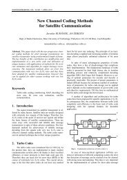
Fig. 7. Calculated and measured co-polarization gain patterns in<br />
x-z plane: a) 880 MHz, b) 920 MHz; c) 960 MHz.
55<br />
55<br />
55<br />
5 6<br />
5 4<br />
5 6<br />
5 4<br />
5 6<br />
5 4<br />
57<br />
53<br />
57<br />
53<br />
57<br />
53<br />
58<br />
52<br />
58<br />
52<br />
58<br />
52<br />
59<br />
51<br />
59<br />
51<br />
59<br />
51<br />
60<br />
50<br />
60<br />
50<br />
60<br />
50<br />
61<br />
49<br />
61<br />
49<br />
61<br />
49<br />
6 2<br />
4 8<br />
6 2<br />
4 8<br />
6 2<br />
4 8<br />
63<br />
47<br />
63<br />
47<br />
63<br />
47<br />
64<br />
46<br />
64<br />
46<br />
64<br />
46<br />
65<br />
45<br />
65<br />
45<br />
65<br />
45<br />
6 6<br />
4 4<br />
6 6<br />
4 4<br />
6 6<br />
4 4<br />
67<br />
43<br />
67<br />
43<br />
67<br />
43<br />
68<br />
42<br />
68<br />
42<br />
68<br />
42<br />
69<br />
41<br />
69<br />
41<br />
69<br />
41<br />
70<br />
40<br />
70<br />
40<br />
70<br />
40<br />
7 1<br />
3 9<br />
7 1<br />
3 9<br />
7 1<br />
3 9<br />
72<br />
38<br />
72<br />
38<br />
72<br />
38<br />
1<br />
37<br />
1<br />
37<br />
1<br />
37<br />
2<br />
36<br />
2<br />
36<br />
2<br />
36<br />
3<br />
35<br />
3<br />
35<br />
3<br />
35<br />
4<br />
3 4<br />
4<br />
3 4<br />
4<br />
3 4<br />
5<br />
33<br />
5<br />
33<br />
5<br />
33<br />
6<br />
32<br />
6<br />
32<br />
6<br />
32<br />
7<br />
31<br />
7<br />
31<br />
7<br />
31<br />
8<br />
30<br />
8<br />
30<br />
8<br />
30<br />
9<br />
2 9<br />
9<br />
2 9<br />
9<br />
2 9<br />
10<br />
28<br />
10<br />
28<br />
10<br />
28<br />
11<br />
27<br />
11<br />
27<br />
11<br />
27<br />
12<br />
26<br />
12<br />
26<br />
12<br />
26<br />
1 3<br />
2 5<br />
1 3<br />
2 5<br />
1 3<br />
2 5<br />
14<br />
24<br />
14<br />
24<br />
14<br />
24<br />
15<br />
23<br />
15<br />
23<br />
15<br />
23<br />
1 6<br />
2 2<br />
1 6<br />
2 2<br />
1 6<br />
2 2<br />
17<br />
21<br />
17<br />
21<br />
17<br />
21<br />
18<br />
20<br />
18<br />
20<br />
18<br />
20<br />
19<br />
19<br />
19<br />
16 D. BONEFAČIĆ, B. RAPINAC, J. BAR<strong>TO</strong>LIĆ, SLOTTED PIFA FOR MOBILE COMMUNICATION DEVICES<br />
-90°<br />
0°<br />
10<br />
[dBi]<br />
0<br />
-10<br />
-20<br />
-30<br />
-40<br />
90°<br />
both ends as well as at the center of the operating frequency<br />
bandwidth. The measurement planes, x-z and y-z,<br />
are defined with coordinate system shown in Fig. 1. The x-<br />
z patterns are almost omnidirectional, while the y-z patterns<br />
have two broad maxima. The patterns do not change significantly<br />
with frequency.<br />
Although simulation results predict very low density<br />
of the current flowing in the ground plane (Fig. 2), measurements<br />
show that the contribution of these currents to the<br />
radiation is significant.<br />
0<br />
-5<br />
a)<br />
-90°<br />
b)<br />
-90°<br />
c)<br />
0°<br />
10<br />
[dBi]<br />
0<br />
-10<br />
-20<br />
-30<br />
-40<br />
0°<br />
10<br />
[dBi]<br />
0<br />
-10<br />
-20<br />
-30<br />
-40<br />
180°<br />
180°<br />
180°<br />
Calculated<br />
Measured<br />
Calculated<br />
Measured<br />
Calculated<br />
Measured<br />
Fig. 8. Calculated and measured co-polarization gain patterns in<br />
y-z plane: a) 880 MHz, b) 920 MHz; c) 960 MHz.<br />
Comparison of the calculated and measured co-polarization<br />
gain patterns are shown in Figs 7 and 8. The<br />
antenna is linearly polarized. The patterns are measured at<br />
90°<br />
90°<br />
S 11 [dB]<br />
-10<br />
-15<br />
-20<br />
-25<br />
-30<br />
-35<br />
-40<br />
850 900 950 1000<br />
Frequency [MHz]<br />
PIFA<br />
PIFA + hand<br />
PIFA + hand + head<br />
Fig. 9. Measured reflection coefficient at the antenna input for<br />
the PIFA alone, for the PIFA with hand phantom, and for<br />
the PIFA with hand and head phantoms.<br />
Preliminary measurement results of the reflection coefficient<br />
at the antenna input for the presented PIFA in the<br />
proximity of human hand and head phantoms are shown in<br />
Fig. 9. For the measurements of the PIFA with only the<br />
hand phantom, the hand phantom was covering approximately<br />
8 cm of the bottom part of the antenna ground<br />
plane. For the measurements of the PIFA with the hand and<br />
head phantom, the position of the hand phantom was the<br />
same while the head phantom was placed 2 cm behind the<br />
ground plane. The first case simulates the application of the<br />
handheld device used with earphones, while the second<br />
simulates the case where the handheld device is placed<br />
near the user's ear. Measurement results in Fig. 9 show that<br />
better impedance matching than the one shown in Fig. 5<br />
can be expected. To enable the comparison, the measured<br />
results from Fig. 5 are repeated on Fig. 9. The presence of<br />
the hand phantom and especially the presence of both the<br />
hand and head phantoms shift the resonant frequency of the<br />
PIFA (Fig. 9). However, in both cases the requirement for<br />
impedance matching at the antenna input (SWR < 3) is<br />
satisfied in the desired operating bandwidth of 880 to<br />
960 MHz. Nevertheless, the influence of the user's hand<br />
and head on the antenna should be reduced. It is expected<br />
that the influence of the user's head can be reduced by<br />
further shaping of the removed part of the ground plane in<br />
order to lower the radiation in the direction of the user's<br />
head. The influence of the user's hand can be reduced by<br />
reducing the RF currents flowing on the ground plane by<br />
RF chokes. Both issues are important not only for<br />
obtaining better radiation properties of the antenna but also
RADIOENGINEERING, VOL. 17, NO. 4, DECEMBER 2008 17<br />
for protecting the user of the exposure to EM fields<br />
generated by the handheld device.<br />
Better impedance matching for the PIFA loaded with<br />
hand and head phantoms is due to the losses in the dielectric<br />
material simulating the human tissue. However, increased<br />
losses implicate gain reduction. Also distortion of<br />
the radiation patterns is expected. These two issues will be<br />
considered in our future work.<br />
4. Conclusion<br />
A slotted PIFA with capacitive loading for operation<br />
in the 880 ÷ 960 MHz band was presented. The modifications<br />
introduced in the PIFA allowed reduction in size. The<br />
PIFA was realized over a ground plane which dimensions<br />
approximately matched the size of a typical handheld device.<br />
The antenna was optimized and the prototype was<br />
fabricated. The input impedance as well as the radiation<br />
patterns and gain were measured. The measured and calculated<br />
results agree reasonably well.<br />
Preliminary results of the influence of human head<br />
and hand phantoms on the antenna characteristics show the<br />
need of reducing the radiation of the antenna in the direction<br />
of the user's head and hand. This will make the antenna<br />
less sensitive to its surrounding during operation and<br />
it will reduce the user's exposure to the electromagnetic<br />
fields generated by the handheld communication device.<br />
Acknowledgements<br />
The authors wish to thank prof. Angelo Freni from<br />
the University of Florence for letting them use the HFSS<br />
electromagnetic field simulator.<br />
This work is supported by ACE (Antenna Center of<br />
Excellence) and by the Ministry of science, education and<br />
sports of the Republic of Croatia.<br />
References<br />
[1] WHEELER, H. A. Fundamental limitations of small antennas.<br />
Proceedings of the IRE, 1947, vol. 35, pp. 1479-1484.<br />
[2] CHU, L. J. Physical limitation on omni-directional antennas. Journal<br />
of Applied Physics, 1948, vol. 19, pp. 1163-1175.<br />
[3] SKRIVERVIK, A. K., ZÜRCHER, J.-F., STAUB, O., MOSIG, J. R.<br />
PCS antenna design: The challenge of miniaturization. IEEE<br />
Antennas and Propag. Magazine, 2001, vol. 43, no. 4, pp. 12 to 26.<br />
[4] MARTÍNEZ-VÁZQUEZ, M. ACE small terminal antennas<br />
activities: a review of the state of the art. In Proc. of the 18 th Int.<br />
Conference on Applied Electromagnetics and Communications<br />
(ICECom 2005). Dubrovnik (Croatia), 2005, pp. 29 to 32.<br />
[5] WONG, K.L. Planar Antennas for Wireless Communications.<br />
Hoboken (New Jersey, USA): J. Wiley, 2003.<br />
[6] HIRASAWA, K. Small antennas for mobile communications. In<br />
Proceedings Antenn00, Nordic Antenna Symposium. Lund (Sweden),<br />
2000, pp. 11 - 15.<br />
[7] KAN, H. K., WATERHOUSE, R. B. Small printed-wing antenna<br />
suitable for wireless handset terminals. Microwave and Optical<br />
Technology Letters, August 2001, vol. 30, no. 4, pp. 226 - 229,<br />
[8] CHAIR, R., LUK, K. M., LEE, K. F., Miniature multilayer shorted<br />
patch antenna. Electronics Letters, 2000, vol. 36, no. 1, pp. 3 - 4.<br />
[9] CHAIR, R., LUK, K. M., LEE, K. F. Miniature shorted dual-patch<br />
antenna. IEE Proc.-Microw. Antennas Propag., 2000, vol. 147, no. 4,<br />
pp. 273 - 276.<br />
[10] KUO, J. S., WONG, K.-L. A low-cost microstrip-line-fed shortedpatch<br />
antenna for a PCS base station. Microwave and Optical<br />
Technology Letters, 2001, vol. 29, no. 3, pp. 146 - 148.<br />
[11] VIRGA, K. L., RAHMAT-SAMII, Y. Low-profile enhancedbandwidth<br />
PIFA antennas for wireless communications packaging.<br />
IEEE Transactions on Microwave Theory and Techniques, 1997, vol.<br />
45, no. 10, pp. 1879 - 1888.<br />
[12] HERSCOVICI, N., FUENTES OSORIO, M., PEIXEIRO, C.<br />
Minimization of a rectangular patch using genetic algorithms. In<br />
Proceedings of the 18 th International Conference on Applied<br />
Electromagnetics and Communications (ICECom 2005). Dubrovnik<br />
(Croatia), 2005, pp. 37 - 40.<br />
[13] KUMAR, G., RAY, K. P. Broadband Microstrip Antennas.<br />
Norwood (MA, USA): Artech House, 2003.<br />
[14] JENSEN, M. A., RAHMAT-SAMII, Y. EM interaction of handsets<br />
antennas and a human in personal communications. Proceedings of<br />
the IEEE, 1995, vol. 83, no. 1, pp. 7-17.<br />
[15] http://www.ansoft.com/products/hf/hfss/<br />
About Authors...<br />
Davor BONEFAČIĆ was born in Zagreb, Croatia, in<br />
1968. He received his Dipl.Ing., Mr.Sc. and Dr.Sc. degrees<br />
from the Faculty of Electrical Engineering and Computing,<br />
University of Zagreb in 1993, 1996, and 2000, respectively.<br />
Since 1993, he has been with the Department of<br />
Wireless Communications, Faculty of Electrical Engineering<br />
and Computing, University of Zagreb. From 1993 to<br />
2002 he worked as a research assistant and from 2002 to<br />
2006 as assistant professor. Currently he is associate professor<br />
at the same Department. His teaching activity includes<br />
several subjects on microwave engineering and<br />
radar systems. In 1996 he was a visiting researcher at the<br />
Third University of Rome, Rome, Italy. In 1996 he was<br />
awarded with the silver plaque "J. Lončar" for outstanding<br />
master thesis. Since 2004 he is a collaborating member of<br />
the Croatian Academy of Engineering. He is co-author of<br />
more than 60 journal articles and conference papers. Besides<br />
teaching and research his professional activity includes<br />
measurement of field distribution and estimation on<br />
health risk of mobile communication base stations and<br />
radar installations, technical inspections of radio broadcasting<br />
stations, and calibration and conformity verification<br />
of RF measurement equipment. His research interests include<br />
active integrated antennas and arrays, spatial power<br />
combining, electronic beam scanning, small and compact<br />
antennas for wireless communications, and wideband<br />
antennas.
18 D. BONEFAČIĆ, B. RAPINAC, J. BAR<strong>TO</strong>LIĆ, SLOTTED PIFA FOR MOBILE COMMUNICATION DEVICES<br />
Bojan RAPINAC was born in 1982, in Zagreb, Croatia.<br />
He received his Dipl.Ing. degree from the Faculty of Electrical<br />
Engineering and Computing, University of Zagreb, in<br />
2007. The same year he received the best student paper<br />
award from the Rector of the University of Zagreb. He is<br />
co-author of one journal paper and 3 conference papers.<br />
Since September 2007 he is with Ericsson Nikola Tesla<br />
Company working as Mobile Softswitch Solution support<br />
engineer. His professional interests include designing small<br />
antennas, programming, 3D modeling.<br />
Juraj BAR<strong>TO</strong>LIĆ was born in Zagreb, Croatia, in 1948.<br />
He received the Dipl. Ing., M.S., and Ph.D. degrees in<br />
Electrical Engineering from the University of Zagreb in<br />
1971, 1975, and 1982, respectively. From 1972 to 1974 he<br />
worked for the Radio Industry of Zagreb in R&D of microwave<br />
radio. In 1974, he joined the Institute for High<br />
Frequency Techniques, Faculty of Electrical Engineering at<br />
the University of Zagreb, were he was a Research Assistant,<br />
Assistant Professor, and Associate Professor. Currently,<br />
he is a Professor in the Department of Wireless<br />
Communications, Faculty of Electrical Engineering and<br />
Computing, University of Zagreb. He served as Head of<br />
the Department from 2000 to 2004. Since 1998 he is<br />
a member of the Croatian Academy of Engineering. He is<br />
the co-author of the book Mixing, Mixers, and Frequency<br />
Synthesizers, and the author and co-author of more then<br />
150 technical papers in journals and conferences. His research<br />
interests include electromagnetics, antennas and<br />
propagation, wireless circuit design, microwave engineering,<br />
and electromagnetic compatibility (EMC). He is<br />
a Senior Member of IEEE.