full-text - Radioengineering
full-text - Radioengineering
full-text - Radioengineering

You also want an ePaper? Increase the reach of your titles
YUMPU automatically turns print PDFs into web optimized ePapers that Google loves.
460 L. J. FOGED, A. SCANNAVINI, EFFICIENT TESTING OF WIRELESS DEVICES FROM 800 MHZ TO 18 GHZ<br />
Efficient Testing of Wireless Devices<br />
from 800 MHz to 18 GHz<br />
Lars Jacob FOGED, Alessandro SCANNAVINI<br />
SATIMO Italy, Via Castelli Romani 59, I-00040 Pomezia Rome, Italy<br />
lfoged@satimo.com, ascannavini@satimo.com<br />
Abstract. Small antennas and other modern communication<br />
applications are using increasingly higher frequencies<br />
while demanding shorter development time and very rapid<br />
testing cycles. A fast and accurate way to exhaustively<br />
determine antenna performance and/or investigate device<br />
malfunction is based on spherical near field measurement<br />
techniques combined with probe array technology.<br />
This paper describes the innovative design aspects of the<br />
StarLab portable antenna measurement system and present<br />
results from the validation campaigns including both<br />
passive and active measurements. The use of integrated<br />
diagnostic and analysis software modules for efficient<br />
antenna design and testing is also presented.<br />
StarLab is flexible with functionalities that can be<br />
easily extended depending on user needs. The equipment<br />
can be interfaced with different RF measurement<br />
instruments, i.e. network analyzer, radio communications<br />
tester etc. in order to perform a large range of both passive<br />
and active antenna measurements.<br />
Antenna measurements are widely used as an integral<br />
part of modern antenna design activities. StarLab is<br />
equipped with integrated software modules in order for<br />
antenna engineer to rapidly find antenna design issues and<br />
take corrective actions in real time [6], [7].<br />
Keywords<br />
Antenna Measurements, Spherical Near Field, Probe<br />
Array, Small Antennas, OTA (over-the-air)<br />
measurements, TRP (Total Radiated Power), TIS<br />
(Total Radiated Sensitivity), CTIA (Cellular<br />
Telecommunications and Internet Association), 3GPP<br />
(3G Partner Partnership).<br />
1. Introduction<br />
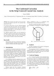
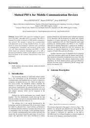
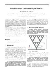
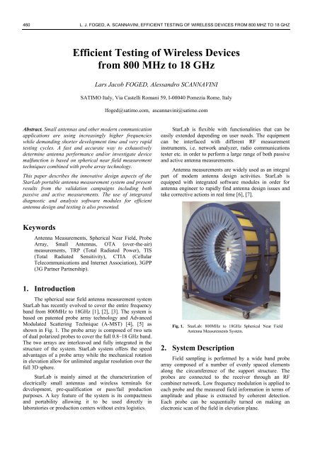
The spherical near field antenna measurement system<br />
StarLab has recently evolved to cover the entire frequency<br />
band from 800MHz to 18GHz [1], [2], [3]. The system is<br />
based on patented probe array technology and Advanced<br />
Modulated Scattering Technique (A-MST) [4], [5] as<br />
shown in Fig. 1. The probe array is composed of two sets<br />
of dual polarized probes to cover the <strong>full</strong> 0.8–18 GHz band.<br />
The two arrays are interleaved and <strong>full</strong>y integrated in the<br />
structure of the system. StarLab system offers the speed<br />
advantages of a probe array while the mechanical rotation<br />
in elevation allow for unlimited angular resolution over the<br />
<strong>full</strong> 3D sphere.<br />
StarLab is mainly aimed at the characterization of<br />
electrically small antennas and wireless terminals for<br />
development, pre-qualification or pass/fail production<br />
purposes. A key feature of the system is its compactness<br />
and portability allowing it to be used directly in<br />
laboratories or production centers without extra logistics.<br />
Fig. 1. StarLab: 800MHz to 18GHz Spherical Near Field<br />
Antenna Measurements System.<br />
2. System Description<br />
Field sampling is performed by a wide band probe<br />
array composed of a number of evenly spaced elements<br />
along the circumference of the support structure. The<br />
probes are connected to the receiver through an RF<br />
combiner network. Low frequency modulation is applied to<br />
each probe and the measured field information in terms of<br />
amplitude and phase is extracted by coherent detection.<br />
Each probe can be sequentially turned on making an<br />
electronic scan of the field in elevation plane.
RADIOENGINEERING, VOL. 18, NO. 4, DECEMBER 2009 461<br />
The Device Under Test (DUT) is located in the centre<br />
of the system on top of a Rohacell ® foam column. The <strong>full</strong><br />
sphere measurement is performed by electronically<br />
scanning the probe array in elevation and rotating the DUT<br />
180° in azimuth. As a consequence a <strong>full</strong> 3D measurement<br />
can be performed very rapidly compared to conventional<br />
single-probe systems.<br />
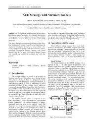
The probe array structure can mechanically rotate<br />
around its center increasing the number of measurement<br />
points by an integer factor (over-sampling factor). This<br />
feature enables the user to perform measurements with an<br />
unlimited number of sampling points as show in Fig. 2.<br />
Fig. 2. Elevation scan using probe array (left), Azimuth scan<br />
using DUT rotation (right).<br />
The probes are wide band printed elements<br />
specifically designed and optimized for probe array<br />
applications. The probes are dual polarized and aligned<br />
according to vertical and horizontal polarizations. The<br />
probes are completely reciprocal and can be used both in<br />
receive and transmit modes. Their assembly also houses<br />
a circuit board containing the control electronics for the<br />
scanning of the probe.<br />
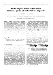
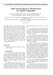
The probe array elements are mounted on a circular<br />
arch and embedded in multi-layer conformal absorbers.<br />
The probe tips protrude through small crossed slots in the<br />
smooth curvature of the absorbers keeping the reflectivity<br />
of the probe array at a minimum. The absorbing material<br />
also reduces scattering and reflections from the support<br />
structure and cabling. The internal diameter of the probe<br />
array in StarLab is 90 cm measured from the tip of one<br />
probe to the tip of the probe on the opposite side. Some<br />
details of the probe array are shown in Fig. 3.<br />
3. Passive/Active Measurements<br />
The StarLab system can be used for performing both<br />
passive and active antenna measurements (OTA). The test<br />
setup is slightly different for passive and active antenna<br />
measurements and involves different support<br />
instrumentation as will be discussed in detail in the<br />
following sections.<br />
3.1 Passive Measurements<br />
Due to the fast probe array technology a <strong>full</strong> 3D<br />
sphere measurements of a passive device can be performed<br />
at a large number of frequency points in the entire<br />
800 MHz to 18 GHz frequency band in a few minutes.<br />
Typical performance parameters such as: 3D pattern, gain,<br />
directivity, efficiency, polarization etc are easily accessed<br />
during post processing. Some typical results are presented<br />
in Section 5 of this paper.<br />
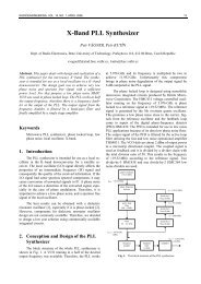
The set-up for passive device measurement is shown<br />
in Fig. 4. The system is connected to a VNA (Vector<br />
Network Analyzer) in order to measure amplitude and<br />
phase signals either being transmitted or received by the<br />
DUT (Device Under Test). For such measurements the<br />
DUT is connected to the VNA by a coax cable running<br />
inside the mast of the StarLab. The control and command<br />
of each probe is performed via a control unit. A USB<br />
interface is used for driving the control unit which allows<br />
to synchronize the probe array acquisition and the azimuth<br />
and elevation positioners. A USB/GPIB converter is used<br />
to control the vector network analyzer.<br />
PC control & acquisition<br />
USB/GPIB<br />
Control<br />
Vector Network Analyser<br />
RF TX<br />
RF RX<br />
StarLab equipment<br />
USB Control<br />
Integrated RF<br />
and control unit<br />
Probe Control<br />
RF TX<br />
RF RX<br />
Azimuth positioner<br />
Elevation positioner<br />
End motion sensor<br />
iti<br />
Power supply<br />
Fig. 4. StarLab Passive Measurements architecture.<br />
Fig. 3. Probe array embedded in conformal multilayer<br />
absorbers. Both the 800 MHz to 6 GHz array and<br />
6 GHz to 18 GHz array elements are visible.<br />
The system is <strong>full</strong>y self-calibrating in a similar<br />
manner widely used in modern VNA’s. The calibration is<br />
carried out in two steps: Orthomodal calibration and gain<br />
calibration. During the orthomodal calibration, a known<br />
reference antenna with good polarization purity is<br />
measured in different positions. This information is used by<br />
the system to calculate frequency dependant calibration<br />
coefficients, for each probe, to improve the probe array<br />
uniformity in terms of polarization and gain response.
462 L. J. FOGED, A. SCANNAVINI, EFFICIENT TESTING OF WIRELESS DEVICES FROM 800 MHZ TO 18 GHZ<br />
The gain calibration is essentially based on the gain<br />
transfer method which has been adapted for spherical nearfield<br />
measurement [8], [9]. A reference antenna with<br />
known gain or efficiency is measured and the system<br />
response is calibrated to reflect the known gain or<br />
efficiency values. Both approaches allow determining the<br />
gain of the AUT according to the IEEE definition [8]. The<br />
orthomodal calibration is performed during maintenance,<br />
when the system is installed in a new location or if it has<br />
been moved significantly. The gain/efficiency calibration is<br />
generally performed on a weekly basis.<br />
3.2 Active Measurements<br />
A <strong>full</strong> 3D sphere measurement of an active device can<br />
be performed at a large number of frequency points in the<br />
operating frequency band in fractions of an hour. Figure of<br />
merits of OTA radiated performances testing are TRP<br />
(Total Radiated Power), and TIS (Total Radiated<br />
Sensitivity). These are integral quantities calculated from<br />
measurements of EIRP (Effective Isotropic Radiated<br />
Power) and EIS (Effective Isotropic Sensitivity) on the <strong>full</strong><br />
3D sphere, surrounding the DUT by using a sampling grid<br />
of 15° and 30°, respectively.<br />
The StarLab active measurements set-up is shown in<br />
Fig. 5. Due to the wide operating bandwidth of the system<br />
it can be used for measuring most of the wireless protocols<br />
available on the wireless market. In the active measurement<br />
scenario there is no physical connection between DUT and<br />
the test system. A radio call must be set up between DUT<br />
and the measurement system using a radio communications<br />
tester in order to perform Over-the-Air (OTA) measurements<br />
based on 3GPP and CTIA standardization.<br />
circuitry, attenuators, and cables impacts are calibrated out<br />
before starting any measurements in order to measure<br />
absolute value of either RX or TX power at mobile phone’s<br />
antenna.<br />
The key elements of active testing are time duration,<br />
accuracy, and repeatability of results. Due to the fast probe<br />
array technology the StarLab system is much faster<br />
compared to traditional one probe system without<br />
degrading the accuracy of results. Fast TIS OTA testing<br />
techniques are usually employed to further increase speed<br />
and reduce measurements time. Representative TRP and<br />
TIS testing performances at CTIA frequencies (850 MHz<br />
and 1900 MHz bands) using StarLab are reported in Tab. 1<br />
and Tab. 2. Averaged performances are based on test<br />
campaign using SATIMO reference DUTs.<br />
TRP measurements<br />
Accuracy Free Space<br />
Accuracy Talk position (Phantom Head)<br />
Repeatability<br />
Measurement Time 3 Channels (CTIA settings)<br />
RADIOENGINEERING, VOL. 18, NO. 4, DECEMBER 2009 463<br />
The StarLab system is <strong>full</strong>y compatible with CTIA<br />
requirements in terms of measurement uncertainty but due<br />
to the limited size of the system it is not compatible with<br />
the requirements on measurement distance.<br />
As an example of an active device measurement the<br />
2D plots of measured EIRP and EIS vs. azimuths and<br />
elevation angle on an E-GSM900 capable device are shown<br />
in Fig. 6 and Fig. 7. Fig. 8 and Fig. 9 show the elevation<br />
pattern @ phi=0° for EIRP and EIS respectively measured<br />
on the same unit. Dipole-like shape of elevation patterns<br />
can be observed.<br />
Fig. 8. Phi = 0° - 3 channels EIRP elevation pattern on E-<br />
GSM 900 capable mobile phone at 897.4 MHz.<br />
SatMap. This software performs spherical backforward<br />
propagation and holography of measured data [4].<br />
For a user specified input power SatMap can calculate the<br />
radiated power density with distance in any direction. This<br />
is an important feature since approval testing is often<br />
specified at different distances than the one of the actual<br />
measurement. SatMap can also perform holographic backprojection,<br />
where electric and magnetic radiated near fields<br />
can be evaluated on planar surfaces everywhere around the<br />
antenna. Field distribution on the radiating plane allows the<br />
user to investigate local radiation and coupling effects.<br />
SatSim is an efficient extension to the fast measurement<br />
capabilities of the SATIMO family of antenna<br />
measurements systems. This code provides a user-friendly<br />
and economical way to accurately evaluate the behavior of<br />
an antenna in its final operational environment based on<br />
near field measurements of the isolated real antenna and<br />
numerical modelling of the environment [5]. Although the<br />
development and validation of the algorithm has been<br />
performed under an ESA contract specifically for<br />
accommodation analyses of spacecraft antennas, the<br />
powerful combination of antenna testing and simulation in<br />
a single environment also has strong potentials in other<br />
related fields.<br />
SatSar is an efficient evaluation tool for SAR<br />
performance of mobile phones. Based on radiated power<br />
measurements in free space and with a phantom, SatSar<br />
correlates the measurements with a data base of SAR and<br />
dissipated power values from the same type of phone<br />
providing an accurate evaluation of the SAR performances.<br />
Fig. 9. Phi = 0° - 3 channels EIS elevation pattern on E-<br />
GSM 900 capable mobile phone at 942.5 MHz.<br />
4. Control, Analysis and Diagnostics<br />
Software Modules<br />
All measurement control and data acquisition<br />
processes are performed by a standard PC running the<br />
proprietary software SatEnv. The software also performs<br />
the post-processing and the visualization of the<br />
measurement data. The StarLab real time interface allows<br />
the user to perform all measurement tasks including real<br />
time visualization of the measured radiation pattern and<br />
set-up of measurement configurations. Through SatEnv the<br />
user has access to a range of additional diagnostics and post<br />
processing features:<br />
4.1 Antenna Diagnostic<br />
By holographic back-projection, electric and magnetic<br />
radiated near fields can be evaluated on a planar surface<br />
almost everywhere around the antenna. The radiated far<br />
field of the antenna is represented by an expansion using<br />
plane waves. The plane wave expansion can be backprojected<br />
to any planar surface and gives insight to the near<br />
field distribution close to the radiating object [6], [7]. From<br />
the tangential and orthogonal field components, important<br />
characteristics of the radiating element can be derived.<br />
Fig. 10 shows an example of a measurement on an<br />
array of 4 x 4 printed dipoles with uniform phase and<br />
amplitude distribution from a corporate type feeding<br />
network. The array has been designed and manufactured<br />
for a WLAN application at 2.5 GHz. Prior to the<br />
measurement, each individual element has been tuned in<br />
the laboratory to optimize the overall return loss of the<br />
array.<br />
Fig. 11 and Fig. 12 show the far field radiation<br />
patterns of the array at 2.5 GHz. Phi = 90° elevation pattern<br />
shows the expected symmetric pattern with -13 dB side<br />
lobes. However, in the phi = 0° elevation cut the pattern<br />
has a small tilt of the main beam and slightly asymmetric<br />
side-lobe levels. The directivity of the array is also slightly<br />
lower than expected due to the larger main beam.
464 L. J. FOGED, A. SCANNAVINI, EFFICIENT TESTING OF WIRELESS DEVICES FROM 800 MHZ TO 18 GHZ<br />
5. Validation and Measurement<br />
Examples<br />
Both passive and active performance of the StarLab<br />
system have been validated by comparative measurements<br />
with other systems or own known reference devices.<br />
Measurement examples and validation activities are<br />
discussed in the following sections.<br />
Fig. 10. 4x4 array of printed dipoles for WLAN application<br />
and measured 3D far-field pattern at 2.5 GHz.<br />
5.1 Passive Measurements<br />
The measured co and cross polar pattern of an<br />
F = 2.45GHz calibration dipole is shown in Fig. 14. The<br />
dipole is a high efficiency sleeve dipole with an innovative<br />
choke minimizing cable and feed point interaction.<br />
Fig. 11. 4x4 dipole array. Measured field at 2.5 GHz, Phi = 0°<br />
Fig. 12. 4x4 dipole array. Measured field at 2.5 GHz, Phi = 90°<br />
By investigating the array far field by holographic<br />
back propagation as shown in Fig. 13 it is clear that the<br />
asymmetry and the decreased directivity are caused by<br />
asymmetry in the array excitation. By investigating further<br />
it was discovered that this asymmetry was introduced by<br />
the individual tuning of the elements. The tuning improved<br />
the overall array matching but also introduced asymmetry<br />
in the excitation of the elements. Fig. 13 shows the holographic<br />
back-projection of the array field on a 0.8m x 0.8m<br />
plane. An amplitude variation of about 1 dB is clearly<br />
visible is the x’-axis plane while symmetry is maintained in<br />
the y’-axis plane.<br />
Fig. 14. Dipole pattern @ 2.45GHz measured in StarLab.<br />
The measured dipole efficiency and gain has been<br />
compared to measurements performed in other ranges and<br />
based on other techniques as discussed in [10]. A very<br />
good correlation between the measurements was observed.<br />
StarLab passive measurements accuracy has also been<br />
validated by comparison with reference data from<br />
international facility comparisons in the frame of the ACE<br />
activities [11]. Two dual ridge horns, the SH800 and<br />
SH2000, have been measured both in European and US<br />
facilities from 800 MHz to 32 GHz. The reported differences<br />
are well within the measurement accuracies of<br />
each of the involved antenna test ranges and the impact of<br />
different set-ups used for testing. Fig. 15 and Fig. 16 show<br />
examples of the radiation pattern comparison at 3 GHz for<br />
the SH800 and the SH2000 at 12 GHz.<br />
Fig. 13. WLAN 4x4 array of dipoles 2D map on horizontal<br />
plane 0.8 x 0.8 meter at z = 0. (|Ex’| -1,-3, -6, -9 dB<br />
from the peak).<br />
Fig. 15. SH800 Radiation patterns comparison at 3 GHz.<br />
StarLab and reference from facility comparison [11].
RADIOENGINEERING, VOL. 18, NO. 4, DECEMBER 2009 465<br />
Fig. 16. SH2000 Radiation patterns comparison at 12 GHz.<br />
StarLab and reference from facility comparison [11].<br />
Several corrugated horns operating the 6–20 GHz<br />
band has been measured in the StarLab system as shown in<br />
Fig. 17 [12], [13]. A comparison of the measured and<br />
predicted Co and Cx polar radiation patterns is shown in<br />
Fig. 18.<br />
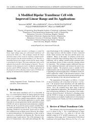
Fig. 19. Efficiency Measurements – Free-space (red curve),<br />
talk position (black curve)<br />
5.2 Active Measurements<br />
StarLab measurements accuracy when performing<br />
TRP and TIS testing has been investigated and validated by<br />
comparing measurements on reference devices (or golden<br />
standards) in different SATIMO systems installed at 3 customer<br />
sites around Europe. The testing has been performed<br />
at different protocol bands: E-GSM 900, GSM 1800,<br />
GSM 1900 and WCDMA Band I.<br />
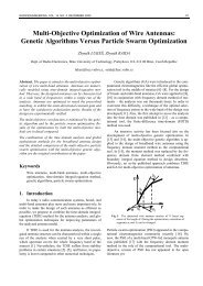
The comparison of the measured TRP and TIS<br />
performances is shown in Fig. 20 and Fig. 21, respectively.<br />
The comparison results show good agreement between the<br />
test ranges used for TRP and TIS testing.<br />
Fig. 17. Dual polarized wide band horn 10–20 GHz.<br />
Fig. 20. TRP Inter-labs comparison results.<br />
Fig. 18. Comparison of measured and predicted Co and Cx<br />
polar radiation patterns at 13 GHz for dual polarized<br />
wide band horn 10–20 GHz.<br />
Fig. 19 shows efficiency measurement data taken in<br />
StarLab. Efficiency has been measured on a dual band<br />
mobile phone in both E-GSM 900, and GSM 1800 bands<br />
when in free-space and talk position (by using a SAM<br />
phantom head). It can be seen that E-GSM900 efficiency<br />
drops from 70 % in free-space to 54 % when in talk<br />
position. The drop in efficiency is more important in<br />
GSM 1800, from 74 % (free-space) to 52 % (talk position).<br />
The same mobile phone has been measured in a SG-64<br />
system showing good match between the two set of<br />
measurements results.<br />
Fig. 21. TIS Inter-labs comparison results.
466 L. J. FOGED, A. SCANNAVINI, EFFICIENT TESTING OF WIRELESS DEVICES FROM 800 MHZ TO 18 GHZ<br />
6. Conclusion<br />
The spherical near field antenna measurement system<br />
StarLab has been presented including the use of integrated<br />
diagnostic and analysis software modules for efficient<br />
antenna design and testing. Measurement examples and<br />
validation comparisons for passive and active antennas and<br />
devices have also been presented.<br />
The system has recently evolved to cover the entire<br />
frequency band from 800 MHz to 18 GHz. The StarLab<br />
system offers the speed advantages of a probe array while<br />
mechanical rotation of the arch allows for unlimited<br />
angular resolution over the <strong>full</strong> sphere. StarLab is mainly<br />
aimed at the characterization of electrically small antennas<br />
and wireless terminals for development, pre-qualification<br />
or pass/fail production purposes.<br />
References<br />
[1] ROBIC, N., DUCHESNE, L., GARREAU, P., GANDOIS, A.,<br />
FOGED, L. J. A compact spherical near-field antenna test system<br />
for 800 MHz to 18 GHz. In 28 th Annual Meeting and Symposium<br />
of Antenna Measurement Techniques Association AMTA 2006.<br />
Austin (USA), 2006.<br />
[2] FOGED, L. J., ESTRADA, J., IVERSEN, P. O. pherical near field<br />
testing of small antennas from 800 MHz to 18 GHz. In IEEE<br />
International Symposium on Antennas and Propagation. Honolusu<br />
(USA), 2007.<br />
[3] ROBIC, N., DUCHESNE, L., GARREAU, P., GANDOIS, A.,<br />
IVERSEN, P. O., FOGED, L. J. A compact spherical near-field<br />
system for antenna testing from 800 MHz to 18 GHz. In The first<br />
European Conference on Antennas and Propagation EuCap 2006.<br />
Nice (France), 2006.<br />
[4] DUCHESNE, L., GARREAU, P., ROBIC, N., GANDOIS, A.,<br />
IVERSEN, P. O., BARONE, G. Compact multi-probe antenna test<br />
station for rapid testing of antennas and wireless terminals. In 26 th<br />
Annual Meeting and Symposium of Antenna Measurement<br />
Techniques Association AMTA 2004. Georgia (USA), 2004.<br />
[5] IVERSEN, P. O., GARREAU, P., ENGLUND, K., PASALIC, E.,<br />
EDVARDSSON, O., ENGBLOM, G. Real time spherical near<br />
field antenna test range for wireless applications. In 21 st Annual<br />
Meeting and Symposium of Antenna Measurement Techniques<br />
Association AMTA 1999. Monterey Bay (USA), 1999.<br />
[6] FOGED, L. J., MIOC, F., IVERSEN, P. O., NOREN, P. Holographic<br />
back-projection for measured low and medium gain<br />
antennas in a spherical near field range. In AMTA Europe<br />
Symposium 2006 Proceedings. Munich (Germany), 2006.<br />
[7] FOGED, L. J., MIOC, F., BENCIVENGA, B., DI GIAM-<br />
PAOLO, E., SABBADINI, M. High frequency numerical<br />
modeling using measured sources. In IEEE AP-S International<br />
Symposium. Albuquerque (USA), 2006.<br />
[8] ANSI/IEEE. IEEE Standard Test Procedures for Antennas,<br />
ANSI/IEEE Std 149-1979 (R2003). 2003.<br />
[9] HANSEN, J. E. Spherical Near-Field Antenna Measurements.<br />
London: Peter Peregrinus, 1988.<br />
[10] GIACOMINI, A., BENCIVENGA, B., DUCHESNE, L., FOGED,<br />
L. J. Determination of high accuracy performance data for dipole<br />
reference antennas. In AMTA Europe Symposium 2006 Proceedings.<br />
Munich (Germany), 2006.<br />
[11] FOGED, L. J., GARREAU, P., BREINBJERG, O., PIVNENKO,<br />
S., CASTAÑER, M., ZACKRISSON, J. Facility comparison and<br />
evaluation using dual ridge horn. In 27th Annual Meeting and<br />
Symposium of Antenna Measurement Techniques Association<br />
AMTA 2005. Newport (USA), 2005.<br />
[12] FOGED, L. J., GIACOMINI, A., MORBIDINI, R., SHETH, V. R.,<br />
SHARMA, S. B., MALAVIYA, R. K., SANADIYA, H. C. Circular<br />
polarised wide-band field probes. In 30 th Annual Meeting and<br />
Symposium of Antenna Measurement Techniques Association<br />
AMTA 2008. Boston (USA), 2008.<br />
[13] FOGED, L. J., GIACOMINI, A., MORBIDINI, R., SCIALAC-<br />
QUA, L. High accuracy field probes in circular polarization. In<br />
IEEE, APS Symposium. Charleston (USA), 2009.<br />
About Authors…<br />
Lars Jacob FOGED was born in Denmark in 1966. He<br />
received his M.Sc. in Electrical Engineering from<br />
California Institute of Technology in 1990. He was with the<br />
European Space Agency in the Netherlands as a “graduate<br />
trainee” and joined Space Engineering in Italy in 1991. He<br />
joined Satimo as deputy director of the office in Italy in<br />
2001. His research interests include: design, numerical<br />
modeling and optimization of antennas, antenna<br />
measurements and standardization issues. In 2008 he was<br />
awarded senior membership of AMTA and since 2004 he is<br />
acting secretary of the IEEE antenna standards committee<br />
and near field working group. He has authored and coauthored<br />
more than 40 journal and conference papers on<br />
antenna design and measurement topics, contributed to 4<br />
books and standards and holds 4 patents.<br />
Alessandro SCANNAVINI was born in Rome in 1971. He<br />
received his M.Sc. in electrical engineering from<br />
University La Sapienza of Rome in December 2000. He<br />
joined Motorola Turin Design Center in March 2001 and<br />
his research interests were in designing, and optimizing<br />
VCO (Voltage Controlled Oscillator), and PLL (Phase<br />
Locked Loop) to be used in GSM, and WCDMA mobile<br />
phones. He was also responsible for designing, and<br />
implementing RF transceivers for GSM, and WCDMA<br />
based handsets. He has got 7 patent disclosures on PLL<br />
designing optimization. He left Motorola in October 2006<br />
to join Altran where he worked as a senior consultant in<br />
Hutchinson Whampoa Ltd (H3G) in Rome. He mostly<br />
focused on chipset architectures’ requirements for<br />
compliancy with 3G deployed networks. He left Altran in<br />
June 2007 to join Satimo SA as a field application engineer<br />
in Europe. He is currently responsible for Satimo and<br />
Orbit/FR European customers and actively participates in<br />
OTA standardization committees. He is also working<br />
closely with R&D department for implementing a MIMO<br />
OTA test range based on Spatial Fading Emulator. He is<br />
a co-author of two papers on MIMO OTA testing.