Sierpinski-Based Conical Monopole Antenna - Radioengineering
Sierpinski-Based Conical Monopole Antenna - Radioengineering
Sierpinski-Based Conical Monopole Antenna - Radioengineering

Create successful ePaper yourself
Turn your PDF publications into a flip-book with our unique Google optimized e-Paper software.
634 P.VŠETULA, Z. RAIDA, SIERPINSKI-BASED CONICAL MONOPOLE ANTENNA<br />
Fig. 2. Frequency response of the planar <strong>Sierpinski</strong> monopole<br />
return loss.<br />
In order to improve the impedance matching, the concept<br />
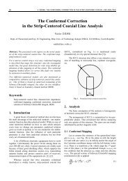
of the modified gasket monopole antenna (Fig. 3) can<br />
be adopted [3]. The vertical distance of the slot from the<br />
ground plane equals to the height of the smallest triangles<br />
of the <strong>Sierpinski</strong> structure [4].<br />
<strong>Sierpinski</strong> monopole Modified gasket monopole<br />
f [GHz] S 11 [dB] BW [MHz] f [GHz] S 11 [dB] BW [MHz]<br />
0.29 –9.74 71 0.31 –8.17 145<br />
1.08 –24.63 25 1.18 –21.34 51<br />
2.39 –15.28 180 2.66 –17.65 126<br />
4.41 –17.89 243 4.63 –33.33 48<br />
Fig. 4. Frequency response of return loss of the planar<br />
<strong>Sierpinski</strong> monopole (blue) and the gasket monopole<br />
antenna (red). Planar structures.<br />
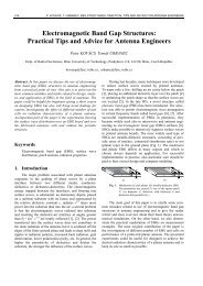
3. <strong>Conical</strong> <strong>Sierpinski</strong>-<strong>Based</strong> <strong>Monopole</strong><br />
In order to improve the symmetry of the radiation and<br />
to make the bandwidth wider, the planar structure is mapped<br />
[3] to the conical surface (Fig. 5).<br />
Tab. 1. Return loss of the conventional <strong>Sierpinski</strong> monopole<br />
(left) and the modified gasket monopole (right) at<br />
operation frequencies. Planar structure assumed.<br />
Frequency response of S 11 of the modified gasket<br />
monopole is depicted in Fig. 4. In the right-hand part of<br />
Tab. 1, magnitudes of S 11 at operation frequencies are<br />
compared with the values of the <strong>Sierpinski</strong> monopole. The<br />
responses are similar.<br />
Fig. 3. Planar gasket monopole antenna.<br />
Radiation patterns of both planar antennas exhibit<br />
asymmetries caused by their asymmetrical geometry<br />
(Fig. 14 and Fig. 15). In order to obtain the omni-directional<br />
pattern in the horizontal plane, geometries of planar<br />
antennas are projected into the conical surface [4].<br />
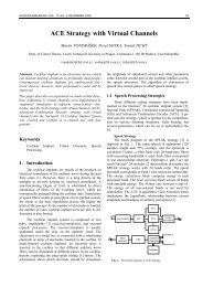
Fig. 5. <strong>Conical</strong> gasket monopole antenna.<br />
Thanks to the conical shape, the omni-directional radiation<br />
and wider operation bandwidth are reached [3].<br />
Heights of segments of the conical gasket monopole are<br />
identical with lengths of segments of the planar antenna.<br />
Frequency response of the reflection coefficient at the<br />
antenna input S 11 is depicted in Fig. 7. Magnitudes of the<br />
reflection coefficient in operation frequency bands are<br />
summarized in the right part of Tab. 2.<br />
Next, the layout of the planar <strong>Sierpinski</strong> monopole<br />
was mapped to the conical surface (Fig. 6). The mapping<br />
resulted in an asymmetrical geometry. Heights of triangles<br />
of the conical antenna are identical with heights of triangles<br />
of the planar <strong>Sierpinski</strong> monopole.<br />
The frequency response of the magnitude of the reflection<br />
coefficient S 11 at the input of the conical <strong>Sierpinski</strong>-based<br />
monopole (Fig. 7) is similar to the characteristics<br />
of the planar <strong>Sierpinski</strong> monopole.