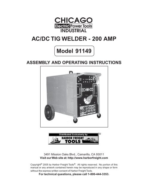
AC/DC TIG WELDER - Harbor Freight Tools
AC/DC TIG WELDER - Harbor Freight Tools
AC/DC TIG WELDER - Harbor Freight Tools

Create successful ePaper yourself
Turn your PDF publications into a flip-book with our unique Google optimized e-Paper software.
<strong>AC</strong>/<strong>DC</strong> <strong>TIG</strong> <strong>WELDER</strong> - 200 AMP<br />
Model 91149<br />
ASSEMBLY AND OPERATING INSTRUCTIONS<br />
®<br />
3491 Mission Oaks Blvd., Camarillo, CA 93011<br />
Visit our Web site at: http://www.harborfreight.com<br />
Copyright © 2005 by <strong>Harbor</strong> <strong>Freight</strong> <strong>Tools</strong> ® . All rights reserved. No portion of this<br />
manual or any artwork contained herein may be reproduced in any shape or form<br />
without the express written consent of <strong>Harbor</strong> <strong>Freight</strong> <strong>Tools</strong>.<br />
For technical questions, please call 1-800-444-3353.
PRODUCT SPECIFICATIONS<br />
Item<br />
Electrical Requirements<br />
Welding Modes (4)<br />
Duty Cycles<br />
Material Capacity<br />
Welding Machine Coolant Type<br />
Gun Gas Hose Length<br />
Ground Clamp Cable Length<br />
Accessories<br />
Weight<br />
Description<br />
Input Voltage: 220V / 60 Hz / 69 Input Amperage<br />
Built-In Thermal Overload Protection<br />
Required Power Cord (not included) Rating: 6 AWG, Maximum length 25’<br />
Must be direct wired to a 220V, 70 Amp, dedicated circuit<br />
<strong>AC</strong> MMA / <strong>DC</strong> MMA / <strong>AC</strong> <strong>TIG</strong> / <strong>DC</strong> <strong>TIG</strong>.<br />
40% @ 200 AMPs <strong>AC</strong> / 60% @ 165 AMPs <strong>AC</strong> / 100% @ 130 AMPs <strong>AC</strong><br />
40% @ 170 AMPs <strong>DC</strong> / 100% @ 110 AMPs <strong>DC</strong><br />
Suitable for all ferrous and non-ferrous metals<br />
Forced Air Cooled<br />
16’ 9-1/2”Long<br />
16’ 9-1/2”Long<br />
Welding Gloves / Welding Mask<br />
Chipping Hammer / Wire Brush<br />
127.05 Pounds<br />
SAVE THIS MANUAL<br />
You will need this manual for the safety warnings and precautions, assembly, operating,<br />
inspection, maintenance and cleaning procedures, parts list and assembly diagram.<br />
Keep your invoice with this manual. Write the invoice number on the inside of the front<br />
cover. Keep this manual and invoice in a safe and dry place for future reference.<br />
UNP<strong>AC</strong>KING<br />
When unpacking, check to make sure all the parts shown on the Parts Lists on pages 23<br />
and 26 are included. If any parts are missing or broken, please call <strong>Harbor</strong> <strong>Freight</strong> <strong>Tools</strong><br />
at the number shown on the cover of this manual as soon as possible.<br />
GENERAL SAFETY RULES<br />
WARNING!<br />
READ AND UNDERSTAND ALL INSTRUCTIONS<br />
Failure to follow all instructions listed below may result in<br />
electric shock, fire, and/or serious injury.<br />
SAVE THESE INSTRUCTIONS<br />
WORK AREA<br />
1. Keep your work area clean and well lit. Cluttered benches and dark areas<br />
invite accidents.<br />
2. Do not operate welding equipment in explosive atmospheres, such as in<br />
the presence of flammable liquids, gases, or dust. Welding equipment<br />
creates sparks which may ignite the dust or fumes.<br />
SKU 91149 For technical questions, please call 1-800-444-3353. PAGE 2
3. Keep bystanders, children, and visitors away while operating welding<br />
equipment. Distractions can cause you to lose control. Protect others in the<br />
work area from arc rays, sparks, and slag. Provide barriers or shields as<br />
needed.<br />
ELECTRICAL SAFETY<br />
1. This Tig Welder requires the connection of a 220 volt electrical cord (not included)<br />
wired directly from the Welder to a 220 volt, (70 Amp) dedicated electrical circuit.<br />
For safety purposes, a qualified, certified, electrician must do this wiring<br />
connection.<br />
2. Avoid body contact with grounded surfaces such as pipes, radiators,<br />
ranges, and refrigerators. There is an increased risk of electric shock if your<br />
body is grounded.<br />
3. Do not expose welding equipment to rain or wet conditions. Water entering<br />
welding equipment will increase the risk of electric shock.<br />
4. Do not abuse the Power Cord. Keep the Power Cord away from heat, oil,<br />
sharp edges, or moving parts. Replace damaged Power Cords immediately.<br />
Damaged Power Cords increase the risk of electric shock.<br />
PERSONAL SAFETY<br />
1. Stay alert. Watch what you are doing, and use common sense when<br />
operating welding equipment. Do not use welding equipment while tired or<br />
under the influence of drugs, alcohol, or medication. A moment of inattention<br />
while operating welding equipment may result in serious personal injury.<br />
2. Dress properly. Do not wear loose clothing or jewelry. Contain long hair.<br />
Keep your hair, clothing, and gloves away from hot or moving parts. Loose<br />
clothes, jewelry, or long hair can be caught in hot or moving parts.<br />
(See page 6, number 3, for recommended safety clothing.)<br />
SKU 91149 For technical questions, please call 1-800-444-3353. PAGE 3
3. Remove adjusting keys or wrenches before turning on the welding<br />
equipment. A wrench or a key that is left attached to an electrically charged part<br />
of the welding equipment may result in personal injury.<br />
4. Do not overreach. Keep proper footing and balance at all times. Proper<br />
footing and balance enables better control of the welding equipment in<br />
unexpected situations.<br />
TOOL USE AND CARE<br />
1. Use clamps (not included) or other practical ways to secure and support<br />
the workpiece to a stable platform. Holding the work by hand or against your<br />
body is unstable and may lead to loss of control.<br />
2. Do not force the welding equipment. Use the correct equipment for your<br />
application. The correct equipment will do the job better and safer at the rate for<br />
which it is designed.<br />
3. Do not use the power tool if the Power Switch does not turn it on or off.<br />
Any equipment that cannot be controlled with the Power Switch is dangerous and<br />
must be replaced.<br />
4. Store idle welding equipment out of reach of children and other untrained<br />
persons. Welding equipment is dangerous in the hands of untrained users.<br />
5. Maintain welding equipment with care. Keep equipmet clean and dry.<br />
Properly maintained equipment is less likely to malfunction and is easier to<br />
control. Do not use damaged welding equipment. Tag damaged equipment “Do<br />
not use” until repaired.<br />
6. Check for misalignment or binding of moving parts, breakage of parts, and<br />
any other condition that may affect the equipment’s operation. If damaged,<br />
have the equipment serviced before using. Many accidents are caused by<br />
poorly maintained equipment.<br />
SKU 91149 For technical questions, please call 1-800-444-3353. PAGE 4
7. Use only accessories that are recommended by the manufacturer for your<br />
model. Accessories that may be suitable for one type of welding equipment may<br />
become hazardous when used on another type of equipment<br />
SERVICE<br />
1. Equipment service must be performed only by qualified repair personnel.<br />
Service or maintenance performed by unqualified personnel could result in a risk<br />
of injury.<br />
2. When servicing welding equipment, use only identical replacement parts.<br />
Follow instructions in the “Inspection, Maintenance, And Cleaning” section<br />
of this manual. Use of unauthorized parts or failure to follow maintenance<br />
instructions may create a risk of electric shock, burns, or other injury.<br />
ELECTRICAL CONNECTION<br />
WARNING! This Tig Welder requires the connection of a 220 volt electrical cord<br />
(not included) wired directly from the Welder to a 220 volt, (70 Amp) dedicated<br />
electrical circuit. For safety purposes, a qualified, certified, electrician must do<br />
this wiring connection.<br />
SYMBOLOGY<br />
Double Insulated<br />
Figure A<br />
V ~<br />
A<br />
no<br />
xxxx/min.<br />
Canadian Standards<br />
Association<br />
Underwriters<br />
Laboratories, Inc.<br />
Volts Alternating Current<br />
Amperes<br />
No Load Revolutions<br />
per Minute (RPM)<br />
SKU 91149 For technical questions, please call 1-800-444-3353. PAGE 5
SPECIFIC SAFETY RULES<br />
1. Maintain a safe working environment. Keep the work area well lit. Make sure<br />
there is adequate surrounding workspace. Always keep the work area free of<br />
obstructions, grease, oil, trash, and other debris. Do not use the Welder in areas<br />
near flammable chemicals, dusts, and vapors.<br />
2. Maintain labels and nameplates on the Welder. These carry important<br />
information. If unreadable or missing, contact <strong>Harbor</strong> <strong>Freight</strong> <strong>Tools</strong> for a<br />
replacement.<br />
3. Prevent eye injury and burns. Wearing and using personal safety clothing and<br />
safety devices reduce the risk of injury. Wear ANSI approved safety impact<br />
eyeglasses with a welding helmut featuring at least a number 10 shade lens<br />
rating. Leather leggings, rubber soled, fire resistant shoes or boots should be<br />
worn when using this Welder. Do not wear pants with cuffs, shirts with open<br />
pockets, or any clothing that can catch and hold molten metal or sparks. Keep<br />
clothing free of grease, oil, solvents, or any other flammable substances. Wear<br />
dry, insulating gloves and protective clothing. Wear an approved head covering to<br />
protect head and neck. Use aprons, cape, sleeves and shoulder covers, and bibs<br />
designed and approved for welding procedures. When welding overhead or in<br />
confined spaces, wear flame resistant ear plugs or ear muffs to keep sparks out of<br />
ears.<br />
4. Avoid overexposure to fumes and gases. Always keep your head out of the<br />
fumes. Do not breathe the fumes. Use enough ventilation or exhaust, or both, to<br />
keep fumes and gases from your breathing zone and general area. Where<br />
ventilation is questionable, have a qualified technician take an air sampling to<br />
determine the need for corrective measures. Use mechanical ventilation to<br />
improve air quality. If engineering controls are not feasible, use an approved<br />
respirator. Work in a confined area only if it is well ventilated, or while wearing an<br />
air-supplied respirator. Follow OSHA guidelines for Permissible Exposure Limits<br />
(PEL’s) for various fumes and gases. Follow the American Conference of<br />
Governmental Industrial Hygienists recommendations for Threshold Limit Values<br />
(TLV’s) for fumes and gases. Have a recognized specialist in Industrial Hygiene<br />
or Environmental Services check the operation and air quality and make<br />
recommendations for the specific welding situation.<br />
5. Do not perform welding or cutting operations near chlorinated hydrocarbon<br />
vapors produced by degreasing or painting. The heat generated by arc rays<br />
can react to form phosgene, a highly toxic gas.<br />
6. Irritation of the eyes, nose, and throat are symptoms of inadequate<br />
ventilation. Take immediate steps to improve ventilation. Do not continue<br />
operations if symptoms persist.<br />
SKU 91149 For technical questions, please call 1-800-444-3353. PAGE 6
7. When welding or cutting in small areas, the operator should be externally<br />
accompanied by another person (standing near the enclosed work area) to<br />
observe accident prevention procedures.<br />
8. When welding or cutting, be aware that high frequency radiation may be<br />
produced which can interfere with radio navigation, safety devices,<br />
computers, and communications equipment. Before operating, have a<br />
qualified technician check out that possibility.<br />
9. Keep high frequency source doors and panels tightly shut. Keep spark<br />
gaps at the correct settings. Use proper grounding and shielding to minimize the<br />
possibility of interference. Keep all cables close together and close to the<br />
ground. Locate the welding or cutting operation as far as possible from sensitive<br />
electronic equipment, or have the electronic equipment shut down temporarily.<br />
10. Prevent accidental fires. Remove any combustible material from the work<br />
area. When possible, move the work to a location well away from combustible<br />
materials. If relocation is not possible, protect the combustibles with a cover<br />
made of fire resistant material. Remove or make safe all combustible materials<br />
for a radius of 35 feet (10 meters) around the work area. Use a fire resistant<br />
material to cover or block all open doorways, windows, cracks, and other<br />
openings. Enclose the work area with portable fire resistant screens. Protect<br />
combustible walls, ceilings, floors, etc., from sparks and heat with fire resistant<br />
covers. If working on a metal wall, floor, ceiling, etc., prevent ignition of<br />
combustibles on the other side by moving the combustibles to a safe location. If<br />
relocation of the combustibles is not possible, designate someone to serve as a<br />
fire watch, equipped with a fire extinguisher, during the welding process and at<br />
least one half hour after the welding is completed. Do not place the torch on any<br />
material other than bare concrete until the torch is completely cooled. Do not<br />
weld on materials having a combustible coating or combustible internal structure<br />
such as walls or ceilings, without an approved method for eliminating the hazard.<br />
Do not dispose of hot slag in containers holding combustible materials. Keep a<br />
fire extinguisher nearby, and know how to use it. After welding, make a thorough<br />
examination for evidence of fire. Be aware that easily visible smoke or flame<br />
may not be present for some time after the fire has started. Do not weld in<br />
atmospheres containing dangerously reactive or flammable gasses, vapors,<br />
liquids, and dust. Provide adequate ventilation in work areas to prevent<br />
accumulation of flammable gases, vapors, or dust. Do not apply heat to a<br />
container that has held an unknown substance or a combustible material whose<br />
contents, when heated, can produce flammable or explosive vapors. Clean and<br />
purge containers before applying heat. Vent closed containers, including<br />
castings, before preheating or welding.<br />
11. Read and understand all instructions and safety precautions as outlined in<br />
the manufacturer’s manual for the material you will weld.<br />
SKU 91149 For technical questions, please call 1-800-444-3353. PAGE 7
12. Industrial applications must follow OSHA requirements.<br />
13. Connect the earth ground as near as possible to the operating area. Earth<br />
connections to structural parts of the building or other places distant to the<br />
operating area will reduce their effectiveness and increase the danger of electric<br />
shock.<br />
14. In addition to grounding the workpiece with the Welder Grounding Clamp, an<br />
earth grounding of the workpiece is recommended. Ground it directly to an<br />
earth pipe or grounding rod with a separate cable of appropriate size.<br />
IMPORTANT: Only a qualified, certified electrician should perform this<br />
procedure.<br />
15. Do not touch the welding wire if you are in contact with the workpiece,<br />
ground, or another welding wire from a different machine.<br />
16. Do not allow the welding wire to touch earth ground. Accidental earth<br />
discharges may cause overheating and fire hazards.<br />
17. Do not pass equipment cables through or near lifting chains, crane cables,<br />
or any electrical lines.<br />
18. Never use the Welder near water. Ensure that the surrounding area and cutting<br />
objects are dry. Do not spray water or other liquids on or near the Welder.<br />
19. Avoid all direct contact between the skin and wet garments and metal parts<br />
under electrical power. Check that gloves and protective clothing are dry.<br />
20. Never leave the Welder unattended when it is turned ON.<br />
21. Always turn off the Welder in the event of a power failure.<br />
22. Significant <strong>DC</strong> electrical voltage exists after turning off the Welder.<br />
Discharge the electrode to ground before handling.<br />
23. Performance of this Welder may vary depending on variations in local line<br />
voltage.<br />
24. Always turn OFF the Welder before performing any inspection, maintenance,<br />
or cleaning procedures.<br />
SKU 91149 For technical questions, please call 1-800-444-3353. PAGE 8
25. Use the right tool or attachment for the right job. Do not attempt to force a<br />
small tool or attachment to do the work of a larger industrial tool or attachment.<br />
There are certain applications for which this product was designed. It will do the<br />
job better and more safely at the rate for which it was intended. Do not modify<br />
this product, and do not use this product for a purpose for which it was not<br />
intended.<br />
26. Proper cylinder care: Secure gas cylinders to the Base of the Welder, a wall, or<br />
post to prevent them from falling. All cylinders should be used and stored in an<br />
upright position. Never drop or strike a cylinder. Do not use cylinders that have<br />
been dented. Cylinder caps should be used when moving or storing cylinders.<br />
Empty cylinders should be kept in specified areas and clearly marked “empty”.<br />
Never use oil or grease on any inlet connector, outlet connector, or cylinder<br />
valve. Additional specific instructions for the safe handling of cylinders should be<br />
supplied by your cylinder supplier and covered under local, state, and federal<br />
regulations governing pressurized gases.<br />
27. WARNING! The brass components of this product contain lead, a chemical<br />
known to the State of Califormia to cause birth defects (or other reproductive<br />
harm). (California Health & Safety code 25249.5, et seq.)<br />
28. WARNING! This product, when used for welding, cutting, and similar<br />
applications, produces chemicals known to the State of Califormia to cause<br />
cancer and birth defects (or other reproductive harm).<br />
(California Health & Safety code 25249.5, et seq.)<br />
29. WARNING! People with pacemakers should consult with their physician(s)<br />
before using this product. Operation of electrical equipment in close proximity to<br />
a heart pacemaker could cause interference or failure of the pacemaker.<br />
30. WARNING! The warnings, precautions, and instructions discussed in this<br />
instruction manual cannot cover all possible conditions and situations that may<br />
occur. It must be understood by the operator that common sense and caution<br />
are factors which cannot be built into this product, but must be supplied by the<br />
operator.<br />
SKU 91149 For technical questions, please call 1-800-444-3353. PAGE 9
PRODUCT OVERVIEW<br />
1. This 200 AMP, <strong>AC</strong>/<strong>DC</strong> <strong>TIG</strong> Welder is designed for the <strong>TIG</strong> and stick welding process, both<br />
in the <strong>AC</strong> and <strong>DC</strong> application.<br />
2. Suitable for all ferrous and non-ferrous materials, including stainless steel, copper,<br />
aluminum and its alloys.<br />
3. Designed with HF (HIgh Frequency) starting which provides non-contact arc starting.<br />
4. Designed with reversible polarity for convenient <strong>DC</strong>EN or <strong>DC</strong>EP performance.<br />
5. Current may be adjusted steplessly by magnetic shunt.<br />
6. Pre-gas time is pre-set inside the machine. Post-gas time may be adjusted from 0-30<br />
seconds.<br />
7. Other design features include; forced air cooling system by fan and overload protection.<br />
6<br />
10<br />
3<br />
12<br />
4<br />
1<br />
Figure B<br />
Part # Description Part # Description<br />
1 Front Panel 6 MMA/<strong>TIG</strong> Selector<br />
3 Post-Gas Potentiometer 10 Power Switch<br />
4 Hand Wheel 12 <strong>AC</strong>/<strong>DC</strong> Main Selector<br />
SKU 91149 For technical questions, please call 1-800-444-3353. PAGE 10
FRONT<br />
COVER<br />
CONTROLS<br />
51B<br />
51A<br />
2<br />
52<br />
50<br />
Part # Description Part # Description<br />
2 Front Cover 51B Negative Terminal<br />
50 2-Pin Socket 52 Gas Hose Outlet<br />
51A Positive Terminal<br />
FIGURE C<br />
B<strong>AC</strong>K<br />
PANEL<br />
CONTROLS<br />
35<br />
36<br />
34<br />
FIGURE D<br />
Part #<br />
Description<br />
34 Gas Hose Inlet<br />
35 Input Terminal Cover<br />
36 Cable Bracket<br />
SKU 91149 For technical questions, please call 1-800-444-3353. PAGE 11
ASSEMBLY INSTRUCTIONS<br />
NOTE: For additional references to the parts listed in the following pages, refer to the<br />
Assembly Diagrams on pages 24 and 26 and Electrical Schematic on page 25.<br />
Electrical Connection:<br />
1. WARNING! This Tig Welder requires the connection of a 220 volt<br />
electrical cord (not included) wired directly from the Welder to a 220 volt, (70<br />
Amp) dedicated electrical circuit. For safety purposes, a qualified, certified,<br />
electrician must do this wiring connection. Required power cord rating:<br />
6 AWG, maximum length 25’.<br />
To Attach The Rear Wheels And Front Castor Wheels:<br />
1. WARNING! Prior to performing any further assembly procedures,<br />
make sure the Power Cord Plug of the Welder is unplugged from its<br />
electrical outlet.<br />
2. To attach the two Front Castor Wheels (53), open the Front Cover (2) of the<br />
Welder. Unscrew and remove the two Bolts that hold the front end of the Base<br />
(49) of the Welder to its shipping pallet. Remove the shipping pallet. Then<br />
screw the Castor Wheels into the threaded mounting holes in the Base.<br />
(See Figure E.)<br />
3. To attach the two Rear Wheels (54) to the Welder, slide a Wheel onto each end<br />
of the Axle located at the rear of the Base (49). Secure both Wheels to the<br />
Axle by inserting one Roll Pin (55) through each end of the Axle.<br />
(See Figure E.)<br />
FIGURE E<br />
ROLL PIN (55)<br />
FRONT CASTOR WHEEL<br />
(53)<br />
REAR WHEEL (54)<br />
SKU 91149 For technical questions, please call 1-800-444-3353. PAGE 12
To Install A Gas Cylinder:<br />
1. CAUTION! Do not use the Argon/Mixed Pressure Regulator/Flow<br />
Meter (6A) with CO 2 shielding gas. To use CO 2 shielding gas, you must<br />
install a CO 2 gas Pressure Regulator/Flow Meter (not included).<br />
2. With assistance, set the cylinder upright to the body of the Welder, wall, or other<br />
stationary support. Secure cylinder with chain (not included). (See Figure F.)<br />
3. Remove the Cap from the cylinder. Stand to the side of the cylinder Valve, and<br />
open the Valve slightly to blow dust and dirt from the Valve. Then, close the<br />
Valve. (See Figure F.)<br />
4. Make sure the Flow Adjust on the Gas Regulator/Flow Meter (6A) is turned<br />
off. Then, screw the Gas Regulator/Flow Meter firmly onto the cylinder Valve.<br />
(See Figure F.)<br />
5. Attach the Regulator Hose (7A) from the Gas Regulator/Flow Meter (6A) to<br />
the Gas Hose Inlet (34) located on the Back Panel (33) of the Welding machine.<br />
(See Figure F.)<br />
6. Adjust the flow rate of the gas by turning the Flow Adjust. The typical flow rate is<br />
20 cfh (cubic feet per hour). Check the welding wire manufacturer’s<br />
recommended flow rate. (See Figure F.)<br />
GAS REGULATOR/FLOW METER (6A)<br />
CYLINDER CAP<br />
CYLINDER VALVE<br />
REGULATOR HOSE<br />
(7A)<br />
FLOW<br />
ADJUST<br />
CHAIN<br />
(NOT INCLUDED)<br />
ARGON GAS<br />
OR<br />
MIXED GAS<br />
B<strong>AC</strong>K PANEL (33)<br />
GAS HOSE INLET (34)<br />
FIGURE F<br />
SKU 91149 For technical questions, please call 1-800-444-3353. PAGE 13
Output Connections For A <strong>TIG</strong> Welding Process With <strong>DC</strong>EN:<br />
Note: Always turn off the Welder before making connection changes.<br />
<strong>DC</strong>EN = Direct Current Electrode Negative.<br />
1. Raise the Front Cover (2) to expose the controls. (See Figure C.)<br />
2. Connect the Welding Gun’s Power Cable (4A) to the Negative Terminal (51B).<br />
Connect the Welding Gun’s Switch Cable (3A) to the 2-Pin Socket (50). Then,<br />
connect the Welding Gun’s Gas Hose (2A) to the Gas Hose Outlet (52).<br />
(See Figure C.)<br />
3. Connect the Ground Clamp Cable (5A) to the Positive Terminal (51A).<br />
(See Figure C.)<br />
4. NOTE: The <strong>DC</strong>EN mode is for a narrow and deep weld penetration,<br />
concentrating 70% of heat on the workpiece and 30% heat on the Welding Gun.<br />
Output Connections For A <strong>TIG</strong> Welding Process With <strong>DC</strong>EP:<br />
<strong>DC</strong>EP = Direct Current Electrode Positive.<br />
1. Raise the Front Cover (2) to expose the controls. (See Figure C.)<br />
2. Connect the Welding Gun’s Power Cable (4A) to the Positive Terminal (51A).<br />
Connect the Welding Gun’s Switch Cable (3A) to the 2-Pin Socket (50). Then,<br />
connect the Welding Gun’s Gas Hose (2A) to the Gas Hose Outlet (52).<br />
(See Figure C.)<br />
3. Connect the Ground Clamp Cable (5A) to the Negative Terminal (51B).<br />
(See Figure C.)<br />
4. NOTE: The <strong>DC</strong>EP mode is for shallow penetration and a strong cleaning action,<br />
concentrating 30% of heat on the workpiece and 70% heat on the Welding Gun.<br />
To Select The Welding Mode:<br />
NOTE: This Welder features 4 welding modes.<br />
1. <strong>AC</strong> MMA = The stick/electrode welding for mild steel. This is the simplest<br />
welding procedure.<br />
A. Move the <strong>TIG</strong> <strong>AC</strong>/<strong>TIG</strong> <strong>DC</strong> Selector (6) to this symbol:<br />
(See Figure B.)<br />
B. Move the <strong>AC</strong>/<strong>DC</strong> Main Selector (12) to this symbol:<br />
(See Figure B.)<br />
SKU 91149 For technical questions, please call 1-800-444-3353. PAGE 14
2. <strong>DC</strong> MMA = The stick/electrode welding for high tensile steel, stainless steel,<br />
aluminum, cast iron.<br />
A. Move the <strong>TIG</strong> <strong>AC</strong>/<strong>TIG</strong> <strong>DC</strong> Selector (6) to this symbol:<br />
(See Figure B.)<br />
B. Move the <strong>AC</strong>/<strong>DC</strong> Main Selector (12) to this symbol:<br />
(See Figure B.)<br />
3. <strong>AC</strong> <strong>TIG</strong> = <strong>TIG</strong> welding for aluminum and magnesium.<br />
A. Move the <strong>TIG</strong> <strong>AC</strong>/<strong>TIG</strong> <strong>DC</strong> Selector (6) to this symbol:<br />
(See Figure B.)<br />
B. Move the <strong>AC</strong>/<strong>DC</strong> Main Selector (12) to this symbol:<br />
(See Figure B.)<br />
4. <strong>DC</strong> <strong>TIG</strong> = <strong>TIG</strong> welding for most ferrous and non-ferrous material except<br />
aluminum and magnesium.<br />
A. Move the <strong>TIG</strong> <strong>AC</strong>/<strong>TIG</strong> <strong>DC</strong> Selector (6) to this symbol:<br />
(See Figure B.)<br />
B. Move the <strong>AC</strong>/<strong>DC</strong> Main Selector (12) to this symbol:<br />
(See Figure B.)<br />
The Post-Gas Potentiometer:<br />
1. The Post-Gas Potentiometer (3) is used to adjust the gas flow time after the<br />
welding current stops. This helps cool the Welding Gun and the ending weld<br />
bead. (See Figure B.)<br />
2. The higher the welding current, the longer the post-flow time should be adjusted<br />
(from 0 to 30 seconds). (See Figure B.)<br />
To Adjust The Welding Current:<br />
1. Rotating the Hand Wheel (4) raises and lowers the output current, allowing the<br />
operator to dial the desired current. (See Figure B.)<br />
2. A clockwise rotation increases the output current. A counterclockwise rotation<br />
decreases the output current. Turning the Hand Wheel drives the pointer which<br />
indicates the welding current. (See Figure B.)<br />
SKU 91149 For technical questions, please call 1-800-444-3353. PAGE 15
Welding Gun Duty Cycle And Overheating:<br />
1. IMPORTANT! Welding longer than the rated duty cycle for this Welding<br />
equipment can damage the Gun and void its warranty.<br />
2. Duty cycle is a percentage of 10 minutes that the unit can weld at its rated load<br />
without overheating. (See Figure G.)<br />
3. If the unit should overheat, the thermostat opens, output stops, and the cooling<br />
fans continue to run. Wait fifteen minutes for the unit to cool. Reduce amperage<br />
or voltage, or duty cycle, before welding.<br />
4. This Welder, at its 40% duty cycle, can run continuously under load for 4 minutes<br />
out of each 10 minute period. (See Figure G.)<br />
5. NOTE: Higher duty cycles can be used at lower currents.<br />
(See Rating Plate information on Front Panel.)<br />
40% Duty Cycle at 200 Amperes (<strong>AC</strong>) Using Mixed Gases<br />
4 Minutes Welding 6 Minutes Resting<br />
Relation Between Duty Cycle And Weld Amperes.<br />
<strong>DC</strong><br />
<strong>AC</strong><br />
DUTY CYCLE (%)<br />
FIGURE G<br />
WELDING CURRENT (AMPs)<br />
SKU 91149 For technical questions, please call 1-800-444-3353. PAGE 16
Welding Current:<br />
1. While the welding current intensity used depends upon size and type of<br />
welding rod, thickness of workpiece, and operating manner or posture, the<br />
relations between sizes of welding rod and operating current intensity, in general,<br />
are shown in Figure H and Figure I below.<br />
Relation Between Size Of Electrode And Welding Current<br />
FIGURE H<br />
Relation Between Size Of Tungsten Electrode And Welding Current<br />
FIGURE I<br />
SKU 91149 For technical questions, please call 1-800-444-3353. PAGE 17
TROUBLESHOOTING GUIDE - WELDING M<strong>AC</strong>HINE<br />
Use larger welding leads.<br />
See Figure L for proper size of tungsten.<br />
See Figure L for proper size of tungsten.<br />
Properly sharpen electrode.<br />
See Figure L for proper size of tungsten.<br />
SKU 91149 For technical questions, please call 1-800-444-3353. PAGE 18
TROUBLESHOOTING GUIDE - WELDING GUN<br />
No arc.<br />
Problem<br />
Arc between gas nozzle<br />
and workpiece.<br />
Welding gun body or<br />
power cable overheated.<br />
Welding wire melted<br />
onto contact tip.<br />
Possible Cause<br />
1. Interruption of welding power circuit to welding<br />
gun or workpiece.<br />
2. Power source or control defective.<br />
1. Spatter build-up inside gas nozzle.<br />
1. Welding current too high.<br />
2. Contact tip not correctly tightened.<br />
3. Ground clamp making poor contact.<br />
4. Contact tip too far away from workpiece.<br />
5. Burn-back time set too long.<br />
INSPECTION, MAINTENANCE, AND CLEANING - WELDING M<strong>AC</strong>HINE<br />
1. WARNING! Make sure the Power Switch (10) is in its “OFF” position.<br />
Unplug the Power Cord Plug from its electrical outlet, and allow the Welder to<br />
completely cool before performing any inspection, maintenance, or cleaning<br />
procedures.<br />
2. Before each use, inspect the general condition of the Welder. Check for<br />
damaged electrical wiring, loose connections, cracked, burnt, or broken parts,<br />
and any other condition that may affect its safe operation. If abnormal noise or<br />
vibration occurs, have the problem corrected before further use.<br />
Do not use damaged equipment.<br />
3. Every six months: Blow off or vacuum dirt and dust deposits on the Welding<br />
Transformer (46) and other components. Dirt or dust deposits on the Welding<br />
Transformer and other internal components may reduce the insulating property or<br />
cause overheated Transformer. During heavy usage, clean monthly.<br />
4. To replace the 3 AMP, 250V Fuse: Failure of the Welder to operate may be<br />
caused by a blown 3 AMP, 250V Fuse (8) as indicated by its melted wire strand<br />
within the Fuse. To replace the Fuse, unscrew and remove the Fuse Cap.<br />
Remove the old Fuse, and install a new 3 AMP, 250V Fuse. Then, replace the<br />
Fuse Cap.<br />
5. When storing, make sure to store the Welder in a safe, clean, dry location out of<br />
reach of children and unauthorized users.<br />
6. All maintenance, service, and repairs not listed in this<br />
manual are only to be attempted by a qualified service technician.<br />
SKU 91149 For technical questions, please call 1-800-444-3353. PAGE 19
INSPECTION, MAINTENANCE, AND CLEANING - WELDING GUN<br />
1. WARNING! Make sure the Power Switch (10) on the Welding Machine is<br />
in its “OFF” position. Unplug the Power from its electrical outlet, and allow the<br />
Welder to completely cool before performing any inspection, maintenance, or<br />
cleaning procedures.<br />
2. Before each use: Inspect the general condition of the Welding Gun. Check for<br />
damaged electrical wiring/gas hose, loose connections, cracked, burnt, or<br />
broken parts, and any other condition that may affect its safe operation. If<br />
abnormal noise or vibration occurs, have the problem corrected before further<br />
use.<br />
Do not use damaged equipment.<br />
3. Before each use: Clean welding spatter from the inside of the Gas Nozzle and<br />
spray with an anti-spatter fluid (not included).<br />
4. To replace the Gun Contact Tip: Remove the Nozzle. Remove the old Contact<br />
Tip (8A), and install a new Contact Tip. Then, replace the Nozzle.<br />
(See Figure J.)<br />
CONT<strong>AC</strong>T TIP (8A)<br />
FIGURE J<br />
NOZZLE<br />
5. To clean exterior of Welding Gun: Use a damp cloth with a mild detergent.<br />
Then, dry. Do not use solvents to clean the Gun.<br />
6. When storing: Make sure to store the Welding Gun in a safe, clean, and dry<br />
location out of reach of children and unauthorized users.<br />
7. CAUTION! All maintenance, service, and repairs not listed in this manual<br />
are only to be performed by a qualified service technician.<br />
SKU 91149 For technical questions, please call 1-800-444-3353. PAGE 20
PLEASE READ THE FOLLOWING CAREFULLY<br />
THE MANUF<strong>AC</strong>TURER AND/OR DISTRIBUTOR HAS PROVIDED THE PARTS LIST<br />
AND ASSEMBLY DIAGRAM IN THIS MANUAL AS A REFERENCE TOOL ONLY.<br />
NEITHER THE MANUF<strong>AC</strong>TURER OR DISTRIBUTOR MAKES ANY REPRESENTATION<br />
OR WARRANTY OF ANY KIND TO THE BUYER THAT HE OR SHE IS QUALIFIED TO<br />
MAKE ANY REPAIRS TO THE PRODUCT, OR THAT HE OR SHE IS QUALIFIED TO<br />
REPL<strong>AC</strong>E ANY PARTS OF THE PRODUCT. IN F<strong>AC</strong>T, THE MANUF<strong>AC</strong>TURER AND/<br />
OR DISTRIBUTOR EXPRESSLY STATES THAT ALL REPAIRS AND PARTS<br />
REPL<strong>AC</strong>EMENTS SHOULD BE UNDERTAKEN BY CERTIFIED AND LICENSED<br />
TECHNICIANS, AND NOT BY THE BUYER. THE BUYER ASSUMES ALL RISK AND<br />
LIABILITY ARISING OUT OF HIS OR HER REPAIRS TO THE ORIGINAL PRODUCT OR<br />
REPL<strong>AC</strong>EMENT PARTS THERETO, OR ARISING OUT OF HIS OR HER INSTALLATION<br />
OF REPL<strong>AC</strong>EMENT PARTS THERETO.<br />
PARTS LIST - WELDING M<strong>AC</strong>HINE<br />
Part # Description Part # Description<br />
1 Front Panel 30 PCB<br />
2 Front Cover 31 Capacitor<br />
3 Post-Gas Potentiometer 32 HV Capacitor<br />
4 Hand Wheel 33 Back Panel<br />
------- ----------------------------------------------------------------- 34 Gas Hose Inlet<br />
6 MMA/<strong>TIG</strong> Mode Selector 35 Input Terminal Cover<br />
7 Operating LED 36 Cable Bracket<br />
8 3 AMP, 250V Fuse 37 Input Terminal<br />
9 Overheating LED 38 Fan<br />
10 Power Switch 39 Solenoid Valve<br />
11 Handle 40 Auxiliary Transformer<br />
12 <strong>AC</strong>/<strong>DC</strong> Main Selector 41 Partition<br />
13 Guide Rail 42 Resistor<br />
14 Magnetic Shunt 43 Spark Gap<br />
15 Spring 44 Rectifier<br />
16 Shunt Support 45 Choke<br />
17 HV Coil 46 Welding Transformer<br />
18 Left Side Panel 47 Magnetic Contractor<br />
19 Frame Support 48 Right Side Panel<br />
20 Roof 49 Base<br />
21 Rubber Pad 50 2-Pin Socket<br />
22 HV Transformer 51 (A) Positive Terminal / (B) Negative Terminal<br />
23 8-Pin Relay Socket 52 5/8” Gas Hose Outlet<br />
24 8-Pin Relay 53 Castor Wheels<br />
25 8-Pin Relay 54 Rear Wheels<br />
26 11-Pin Relay Socket 55 Roll Pins<br />
27 11-Pin Relay<br />
28 PCB<br />
29 PCB<br />
NOTE:<br />
Some parts are listed and shown<br />
for illustration purposes only,<br />
and are not available individually<br />
as replacement parts.<br />
SKU 91149 For technical questions, please call 1-800-444-3353. PAGE 21
ASSEMBLY DIAGRAM - WELDING M<strong>AC</strong>HINE<br />
55<br />
54<br />
53<br />
NOTE:<br />
Some parts are listed and shown<br />
for illustration purposes only,<br />
and are not available individually<br />
as replacement parts.<br />
SKU 91149 For technical questions, please call 1-800-444-3353. PAGE 22
ELECTRICAL SCHEMATIC - WELDING M<strong>AC</strong>HINE<br />
NOTE:<br />
Some parts are listed and shown<br />
for illustration purposes only,<br />
and are not available individually<br />
as replacement parts.<br />
SKU 91149 For technical questions, please call 1-800-444-3353. PAGE 23
PARTS LIST - WELDING GUN & <strong>AC</strong>CESSORIES<br />
Part # Description Part # Description<br />
1A Welding Gun 7A Regulator Hose<br />
2A Gas Hose 8A Contact Tip (Quantity = 3)<br />
3A Switch Cable 9A Welding Gloves (not shown)<br />
4A Power Cable 10A Chipping Hammer (not shown)<br />
5A Ground Clamp Cable 11A Wire Brush (not shown)<br />
6A Gas Regulator/Flow Meter 12A Welding Mask (not shown)<br />
ASSEMBLY DIAGRAM - WELDING GUN & <strong>AC</strong>CESSORIES<br />
4A<br />
3A<br />
2A<br />
1A<br />
6A<br />
7A<br />
8A 8A 8A<br />
5A<br />
9A: WELDING GLOVES NOT SHOWN.<br />
10A: CHIPPING HAMMER NOT SHOWN.<br />
11A: WIRE BRUSH NOT SHOWN.<br />
12A: WELDING MASK NOT SHOWN.<br />
NOTE:<br />
Some parts are listed and shown<br />
for illustration purposes only,<br />
and are not available individually<br />
as replacement parts.<br />
SKU 91149 For technical questions, please call 1-800-444-3353. PAGE 24