PICAXE AND XBEE TUTORIAL
PICAXE AND XBEE TUTORIAL
PICAXE AND XBEE TUTORIAL

Create successful ePaper yourself
Turn your PDF publications into a flip-book with our unique Google optimized e-Paper software.
<strong>PICAXE</strong> <strong>AND</strong> <strong>XBEE</strong> <strong>TUTORIAL</strong><br />
Contents:<br />
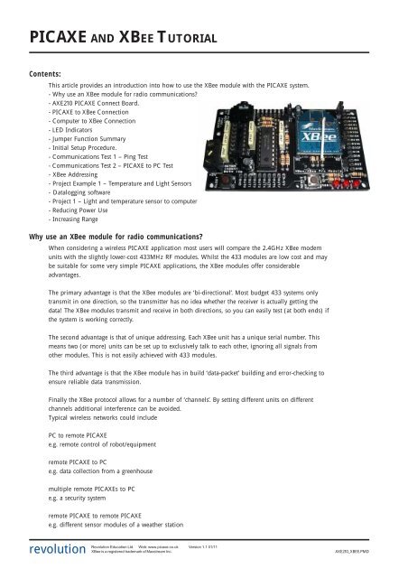
This article provides an introduction into how to use the XBee module with the <strong>PICAXE</strong> system.<br />
- Why use an XBee module for radio communications?<br />
- AXE210 <strong>PICAXE</strong> Connect Board.<br />
- <strong>PICAXE</strong> to XBee Connection<br />
- Computer to XBee Connection<br />
- LED Indicators<br />
- Jumper Function Summary<br />
- Initial Setup Procedure.<br />
- Communications Test 1 – Ping Test<br />
- Communications Test 2 – <strong>PICAXE</strong> to PC Test<br />
- XBee Addressing<br />
- Project Example 1 – Temperature and Light Sensors<br />
- Datalogging software<br />
- Project 1 – Light and temperature sensor to computer<br />
- Reducing Power Use<br />
- Increasing Range<br />
Why use an XBee module for radio communications?<br />
When considering a wireless <strong>PICAXE</strong> application most users will compare the 2.4GHz XBee modem<br />
units with the slightly lower-cost 433MHz RF modules. Whilst the 433 modules are low cost and may<br />
be suitable for some very simple <strong>PICAXE</strong> applications, the XBee modules offer considerable<br />
advantages.<br />
The primary advantage is that the XBee modules are ‘bi-directional’. Most budget 433 systems only<br />
transmit in one direction, so the transmitter has no idea whether the receiver is actually getting the<br />
data! The XBee modules transmit and receive in both directions, so you can easily test (at both ends) if<br />
the system is working correctly.<br />
The second advantage is that of unique addressing. Each XBee unit has a unique serial number. This<br />
means two (or more) units can be set up to exclusively talk to each other, ignoring all signals from<br />
other modules. This is not easily achieved with 433 modules.<br />
The third advantage is that the XBee module has in build ‘data-packet’ building and error-checking to<br />
ensure reliable data transmission.<br />
Finally the XBee protocol allows for a number of ‘channels’. By setting different units on different<br />
channels additional interference can be avoided.<br />
Typical wireless networks could include<br />
PC to remote <strong>PICAXE</strong><br />
e.g. remote control of robot/equipment<br />
remote <strong>PICAXE</strong> to PC<br />
e.g. data collection from a greenhouse<br />
multiple remote <strong>PICAXE</strong>s to PC<br />
e.g. a security system<br />
remote <strong>PICAXE</strong> to remote <strong>PICAXE</strong><br />
e.g. different sensor modules of a weather station<br />
revolution<br />
Revolution Education Ltd. Web: www.picaxe.co.uk Version 1.1 01/11<br />
XBee is a registered trademark of Maxstream Inc.<br />
AXE210_<strong>XBEE</strong>.PMD
<strong>PICAXE</strong> and the XBee Module<br />
2<br />
AXE210 <strong>PICAXE</strong> Connect Board.<br />
This tutorial assumes that you have already purchased and assembled two<br />
<strong>PICAXE</strong> ‘AXE210 Connect’ boards. Details on how to assemble these boards are<br />
provided in the separate datasheet AXE210.pdf, available from www.picaxe.co.uk<br />
The <strong>PICAXE</strong> ‘AXE210 Connect Board’ has been designed to allow two modes of<br />
use:<br />
- as a <strong>PICAXE</strong> to XBee wireless modem interface (<strong>PICAXE</strong> chip inserted)<br />
- as a computer to XBee wireless modem interface (MAX3232 chip<br />
inserted)<br />
This allows, for instance, a sensor connected to a <strong>PICAXE</strong> chip (on one AXE210<br />
board) to transmit data to a second AXE210 board that is directly connected to a<br />
computer – allowing the remote data to be displayed and recorded on the<br />
computer screen!<br />
Important Note:<br />
When used as a <strong>PICAXE</strong> interface the <strong>PICAXE</strong> chip is inserted in the 18 pin socket.<br />
When used as a computer interface a MAX3232CPE chip is inserted in the 16 pin<br />
socket. Never insert both the <strong>PICAXE</strong> chip and MAX3232 chip at the same time!<br />
<strong>PICAXE</strong> to XBee Connection<br />
When a <strong>PICAXE</strong> chip is inserted in the 18 pin socket the following connections<br />
are made:<br />
<strong>PICAXE</strong> output B.7 is connected to the XBee transmit pin (via jumper J1).<br />
<strong>PICAXE</strong> output B.6 is connected to the XBee sleep pin (via jumper J4)<br />
<strong>PICAXE</strong> input C.7 is connected to the XBee receive pin.<br />
Therefore data to be transmitted by the XBee module can be output via the<br />
<strong>PICAXE</strong> command serout e.g.<br />
serout B.7,T2400,(“Data”)<br />
Data received by the XBee module can be processed by the <strong>PICAXE</strong> command<br />
serin e.g.<br />
serin C.7,T2400, b1<br />
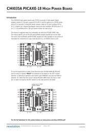
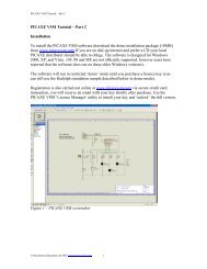
As the <strong>PICAXE</strong> operates at 5V, whilst the XBee operates at 3.3V, the output pins<br />
from the <strong>PICAXE</strong> are interfaced to the XBee via a simple potential divider<br />
arrangement.<br />
AXE210 - <strong>PICAXE</strong> Circuit<br />
5V<br />
C1<br />
4k7<br />
14<br />
V+<br />
4<br />
Reset<br />
<strong>PICAXE</strong><br />
0V<br />
5<br />
In7<br />
16<br />
Out7<br />
13<br />
Out6<br />
12<br />
Rcv<br />
3<br />
Txd<br />
2<br />
22k<br />
180<br />
J4<br />
10k<br />
10k<br />
XBee<br />
Sleep<br />
10k<br />
10k<br />
J1<br />
XBee<br />
TXD<br />
XBee<br />
RXD<br />
RESET<br />
CONN1<br />
10k<br />
10k<br />
10k<br />
0V<br />
revolution<br />
Revolution Education Ltd. Web: www.picaxe.co.uk Version 1.1 01/11<br />
XBee is a registered trademark of Maxstream Inc.<br />
AXE210_<strong>XBEE</strong>.PMD
<strong>PICAXE</strong> and the XBee Module<br />
3<br />
Computer to XBee Connection<br />
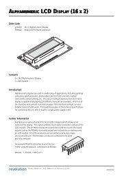
When a MAX3232 chip is inserted in the 16pin socket the XBee module is connected<br />
(via the download cable) directly to the computer serial port. Therefore data can be<br />
transmitted from/received by the computer. The XBee module can also be configured<br />
via use of the Programming Editor XBee Wizard or configuration commands (see XBee<br />
Manual for more details).<br />
If your laptop computer does not have an old style 9 pin serial port you will require<br />
the AXE027 USB cable.<br />
Remember - never insert both the <strong>PICAXE</strong> chip and MAX3232 chip at the same time.<br />
3.3V<br />
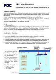
AXE210 - MAX3232 Circuit<br />
100n<br />
16<br />
MAX3232<br />
V+<br />
1<br />
2<br />
C1+ V+<br />
100n<br />
6<br />
V-<br />
3<br />
C1-<br />
4<br />
14<br />
C2+ T1OUT<br />
12<br />
R1OUT<br />
XBee<br />
TXD<br />
100n<br />
5<br />
C2-<br />
13<br />
R1IN<br />
11<br />
T1IN<br />
0V<br />
15<br />
100n<br />
100n<br />
J1<br />
XBee<br />
RXD<br />
CONN1<br />
0V<br />
AXE210 - Power Circuit<br />
5V<br />
CONN2<br />
9V<br />
0V<br />
5V<br />
MCP1702<br />
500<br />
MCP1702<br />
330<br />
+ +<br />
3.3V<br />
100u<br />
4u7<br />
100n<br />
0V<br />
revolution<br />
Revolution Education Ltd. Web: www.picaxe.co.uk Version 1.1 01/11<br />
XBee is a registered trademark of Maxstream Inc.<br />
AXE210_<strong>XBEE</strong>.PMD
<strong>PICAXE</strong> and the XBee Module<br />
4<br />
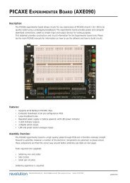
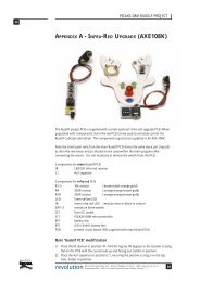
LED Indicators<br />
The AXE210 board has three LED indicators.<br />
RSSI connects to the XBee RSSI pin (pin 6)<br />
STATUS connects to the XBee ON/Sleep pin (pin 13<br />
IND connects via Jumper 3 to either XBee<br />
Associate pin (pin 15) or Transmit pin (pin 11)<br />
RSSI<br />
STATUS<br />
IND<br />
3.3V<br />
indicates the XBee received signal strength<br />
indicates whether the XBee module is active/sleeping<br />
indicates whether the XBee module has associated with another module<br />
(Associate position) or is transmitting data (Transmit position).<br />
AXE210 XBee circuit<br />
XBee<br />
1<br />
V+<br />
Vref<br />
14<br />
J2<br />
From/To<br />
PICXAE/<br />
MAX3232<br />
J1<br />
2<br />
3<br />
TXD<br />
RCV<br />
TX<br />
11<br />
Assoc<br />
15<br />
ON<br />
13<br />
RSSI<br />
6<br />
J3<br />
From<br />
<strong>PICAXE</strong><br />
9<br />
DI8<br />
0V<br />
10<br />
Reset<br />
5<br />
Reset<br />
180<br />
180<br />
180<br />
0V<br />
Jumper Function Summary<br />
The AXE210 board has 4 jumpers, labelled J1 to J4.<br />
The default position of each jumper is shown in bold.<br />
J1<br />
Open<br />
Top<br />
Bottom<br />
- (not used)<br />
- Normal use<br />
- Loopback test (XBee DOUT connected to DIN)<br />
J2<br />
Open - XBee Vref not connected<br />
Fitted - XBee Vref connected to 3.3V<br />
J3<br />
Open<br />
Top<br />
Bottom<br />
- IND. LED not connected<br />
- IND. LED connected to XBee Transmit (DIO4)<br />
- IND. LED connected to XBee Associate (DIO5)<br />
J4<br />
Open<br />
Fitted<br />
- <strong>PICAXE</strong> output 6 not connected<br />
- <strong>PICAXE</strong> output 6 connected to XBee sleep pin (DI8)<br />
revolution<br />
Revolution Education Ltd. Web: www.picaxe.co.uk Version 1.1 01/11<br />
XBee is a registered trademark of Maxstream Inc.<br />
AXE210_<strong>XBEE</strong>.PMD
<strong>PICAXE</strong> and the XBee Module<br />
5<br />
Initial Setup Procedure.<br />
For the initial setup procedure you require two AXE210 connect boards<br />
Board A should contain a MAX3232CPE chip.<br />
Board B should contain a <strong>PICAXE</strong>-18M2 (or older 18A or 18X) chip.<br />
Remember NEVER insert both chips into the same board!<br />
Board A Configuration<br />
MAX3232CPE chip fitted.<br />
Jumper 1 ‘top’ position.<br />
Jumper 2 fitted.<br />
Jumper 3 ‘bottom’ position.<br />
Jumper 4 not fitted.<br />
Board B Configuration<br />
<strong>PICAXE</strong> chip fitted.<br />
Jumper 1 ‘bottom’ position.<br />
Jumper 2 fitted.<br />
Jumper 3 ‘bottom’ position.<br />
Jumper 4 not fitted.<br />
The purpose of this procedure is to reset and then configure the two XBee modules so that they can<br />
communicate. It does not use the <strong>PICAXE</strong> chip (see test 2).<br />
1. Insert one XBee module into board A.<br />
2. Connect board A to the <strong>PICAXE</strong> download cable.<br />
3. Run the Programming Editor software. Ensure the correct serial port is selected<br />
(View>Options>Serial Port menu).<br />
4. Select the <strong>PICAXE</strong>>Wizard>AXE210 <strong>PICAXE</strong> Connect>XBee Setup menu.<br />
5. Make sure the PC baud rate option matches the current XBee setting. For new modules this will<br />
be 9600.<br />
6. Click the ‘Read Version’ button. This will confirm the module is correctly powered and<br />
connected.<br />
7. If not using a new module, click the ‘Factory Reset’ button. This will reset all current settings of<br />
the XBee module, and also reset the baud rate to 9600.<br />
8. In the ‘Set XBee baud rate’ option select 2400. Click ‘Write’ to configure the XBee to always use<br />
a baud rate of 2400. The ‘PC baud rate’ option will now also automatically change to 2400.<br />
9. Click the ‘Read Version’ button again. This will<br />
confirm the module is correctly operating at the new<br />
baud rate.<br />
10. Remove the XBee module and put into board B.<br />
11. Repeat steps 5-9 for the second XBee module, so that<br />
it is also working at a baud rate of 2400.<br />
Both modules are now set in the default configuration,<br />
at a baud rate of 2400. In this condition they will<br />
respond to any XBee module (ie they are address<br />
independent). We will look at how to use unique<br />
addresses next time. The boards are now ready for<br />
Communications Test 1.<br />
revolution<br />
Revolution Education Ltd. Web: www.picaxe.co.uk Version 1.1 01/11<br />
XBee is a registered trademark of Maxstream Inc.<br />
AXE210_<strong>XBEE</strong>.PMD
<strong>PICAXE</strong> and the XBee Module<br />
6<br />
Communications Test 1 – Ping Test<br />
Board A Configuration<br />
MAX3232CPE chip fitted.<br />
Jumper 1 ‘top’ position.<br />
Jumper 2 fitted.<br />
Jumper 3 ‘bottom’ position.<br />
Jumper 4 not fitted.<br />
Board B Configuration<br />
<strong>PICAXE</strong> chip fitted.<br />
Jumper 1 ‘bottom’ position.<br />
Jumper 2 fitted.<br />
Jumper 3 ‘bottom’ position.<br />
Jumper 4 not fitted.<br />
To test communication between the modules we first perform a ‘ping test’. In this test<br />
the computer sends serial data to the XBee module on board A. Board A then<br />
transmits the data over the wireless link. This data is received by board B and<br />
immediately ‘pinged’ (echoed) back to module A, which in turn transmits the<br />
received data back up the serial cable to the computer. The <strong>PICAXE</strong> chip is not used,<br />
as is it bypassed via jumper link 1 on board B. This jumper link connects the RX and<br />
TX lines of the XBee module together, so that anything received by the XBee module<br />
is instantly transmitted back as an ‘echo’.<br />
1. Connect board A to the <strong>PICAXE</strong> download cable.<br />
2. Place board B approximately 1m away from board A.<br />
3. Run the Programming Editor software. Ensure the correct serial port is selected<br />
(View>Options>Serial Port menu).<br />
4. Select the <strong>PICAXE</strong>>Wizard>AXE210 <strong>PICAXE</strong> Connect>XBee Setup menu.<br />
5. Make sure the PC baud rate option matches the current XBee setting, which<br />
should be 2400.<br />
6. Click the ‘Ping Test’ button. If all boards are configured correctly and operating a<br />
text string will be transmitted by board A, echoed by board B, and then displayed<br />
on the computer screen. The RSSI LED on both boards should light whilst they are<br />
communicating.<br />
revolution<br />
Revolution Education Ltd. Web: www.picaxe.co.uk Version 1.1 01/11<br />
XBee is a registered trademark of Maxstream Inc.<br />
AXE210_<strong>XBEE</strong>.PMD
<strong>PICAXE</strong> and the XBee Module<br />
7<br />
Communications Test 2 – <strong>PICAXE</strong> to PC Test<br />
Board A Configuration<br />
MAX3232CPE chip fitted.<br />
Jumper 1 ‘top’ position.<br />
Jumper 2 fitted.<br />
Jumper 3 ‘bottom’ position.<br />
Jumper 4 not fitted.<br />
Board B Configuration<br />
<strong>PICAXE</strong> chip fitted.<br />
Jumper 1 ‘top’ position.<br />
Jumper 2 fitted.<br />
Jumper 3 ‘bottom’ position.<br />
Jumper 4 not fitted.<br />
If you have just performed test 1 remember to move the ‘Jumper 1’ position on<br />
board B.<br />
In this second test, data is transmitted from the <strong>PICAXE</strong> chip on board B. The data is<br />
received by board A, which then displays the data on the computer screen. This tests<br />
that the <strong>PICAXE</strong> chip can transmit data over the wireless link.<br />
1. Connect the <strong>PICAXE</strong> download cable to board B.<br />
2. Download the following program into the <strong>PICAXE</strong> chip.<br />
init: high 7<br />
pause 100<br />
main: serout 7, T2400, (“Value =”, #b1,CR,LF)<br />
let b1 = b1 + 1<br />
pause 500<br />
goto main<br />
3. Remove the download cable from board B and connect to board A.<br />
4. Click the <strong>PICAXE</strong>>Terminal menu and make sure the baud rate is set to 2400.<br />
5. The data being transmitted by board B should now be displayed in the terminal<br />
Window.<br />
revolution<br />
Revolution Education Ltd. Web: www.picaxe.co.uk Version 1.1 01/11<br />
XBee is a registered trademark of Maxstream Inc.<br />
AXE210_<strong>XBEE</strong>.PMD
<strong>PICAXE</strong> and the XBee Module<br />
8<br />
XBee Addressing<br />
The previous two tests used the XBee module in its default state, where it will<br />
broadcast to, and receive data from, any other XBee module. However one of the<br />
main advantages of the XBee modules is that they can be configured to communicate<br />
with unique devices – e.g. two modules can be setup so they will only ‘talk’ to each<br />
other, ignoring information from any other module. So it is also useful to study a<br />
couple of sample projects where the modules are configured to only talk to each<br />
other.<br />
Before going any further it is necessary to define some XBee terms. It is also strongly<br />
recommended that the XBee datasheet (available from www.maxstream.net) is<br />
studied.<br />
Broadcast Channel <br />
The XBee modules can communicate on different ‘broadcast channels’. All XBee<br />
modules in the same network must be on the same channel. By placing different<br />
networks on different channels, interference can be reduced. By changing channel you<br />
may also reduce interference from, for instance, a home computer WiFi setup.<br />
Baud Rate <br />
To communicate, all XBee units must be operating at the same baud rate. For <strong>PICAXE</strong><br />
setups it is recommended to use a baud rate setting of 2400, as this is compatible<br />
with all <strong>PICAXE</strong> chips. Although this is fairly slow by modern standards, it is quite<br />
adequate for most <strong>PICAXE</strong> projects.<br />
Network Group <br />
The XBee modules can be configured to work in ‘Network Groups’ (referred to as<br />
‘PAN ID’ in the XBee documentation). Each module will only respond to devices in<br />
its own group. The group is defined by a 16-bit number.<br />
Serial Number <br />
Each XBee unit has a unique 64-bit serial number (aka ‘long address’). This serial<br />
number is factory loaded and cannot be changed. When transmitting data you can<br />
choose to address the data to a unique device, identified by its serial number. The<br />
serial number is printed on the bottom of the XBee module.<br />
Nickname <br />
Each XBee unit can also be set with a user configurable 16-bit ‘my nickname’ (aka<br />
‘short address’). The advantage of the ‘nickname’ over the serial number is that it<br />
uses less memory in a <strong>PICAXE</strong> program. It also allows XBee units to be easily<br />
interchanged within an existing system by re-programming a replacement module<br />
(which would have a different serial number) with the existing nickname.<br />
Summary for successful communication between XBee units:<br />
1) All modules that wish to communicate must use the same baud rate.<br />
2) All modules that wish to communicate must be on the same broadcast channel.<br />
3) All modules that wish to communicate must be in the same network group.<br />
4) Each XBee module can be configured to transmit to:<br />
· Any module<br />
· Module(s) with a specific ‘nickname’<br />
· A unique module with a specific ‘serial number’<br />
5) Each XBee module can be configured to receive data:<br />
· From any module<br />
· Only when its ‘nickname’ is used<br />
· Only when its ‘serial number’ is used<br />
revolution<br />
Revolution Education Ltd. Web: www.picaxe.co.uk Version 1.1 01/11<br />
XBee is a registered trademark of Maxstream Inc.<br />
AXE210_<strong>XBEE</strong>.PMD
<strong>PICAXE</strong> and the XBee Module<br />
9<br />
Project Example 1 – Temperature and Light Sensors<br />
In this first example project a DS18B20 temperature sensor and a Light<br />
Dependant Resistor are connected to the <strong>PICAXE</strong>-18X chip. The data from these<br />
sensors is then transmitted to a second XBee unit that is connected to a<br />
computer.Unique ‘nickname’ addressing will be used, so the data is only shared<br />
by these two modules. In this case the nickname of module 1 will be set to<br />
‘1234’ and the nickname of module 2 to ‘4321’.<br />
The first task is to configure the two XBee modules with the correct settings using<br />
the Wizard in the <strong>PICAXE</strong> Programming Editor software. To do this insert the<br />
MAX3232 chip into the AXE210 connect board (remove any <strong>PICAXE</strong> chip) and<br />
make sure jumper J1 is in the ’top’ position. Then click the<br />
<strong>PICAXE</strong>>Wizards>AXE210 Connect>XBee Setup menu.<br />
The settings required by each module are shown below:<br />
XBee (Board A) XBee (Board B)<br />
Baud Rate 2400 2400<br />
Broadcast Channel C C<br />
Network Group (PAN ID) 3332 3332<br />
Destination nickname 4321 1234<br />
My short nickname 1234 4321<br />
Note that all the settings are the same, apart from the ‘my nickname’ and<br />
‘destination nickname’ values which are swapped between the two modules so<br />
that they can correctly identify each other.<br />
After programming the units (by pressing the ‘Write’ button in each section) it is<br />
a good idea to do a ‘Ping Test’ to check the two units are communicating correctly<br />
with each other. Details of how to do this test are given in the initial setup<br />
procedure.<br />
On one AXE210 connect board (board A) insert a <strong>PICAXE</strong> chip and then connect a<br />
LDR light sensor and a DS18B20 temperature sensor to the <strong>PICAXE</strong> input pins (at<br />
the top of the board) as shown below. The LDR is connected to input 0 and the<br />
temperature sensor to input 1.<br />
5V<br />
4k7<br />
LDR<br />
temperature<br />
sensor<br />
DS18B20<br />
input<br />
pin1<br />
input<br />
pin0<br />
V+<br />
0V<br />
<strong>PICAXE</strong><br />
V+<br />
data<br />
0V<br />
0V<br />
10k<br />
revolution<br />
Revolution Education Ltd. Web: www.picaxe.co.uk Version 1.1 01/11<br />
XBee is a registered trademark of Maxstream Inc.<br />
AXE210_<strong>XBEE</strong>.PMD
<strong>PICAXE</strong> and the XBee Module<br />
10<br />
Connect board A to the computer and download the following program into the<br />
<strong>PICAXE</strong> chip. It reads the light and temperature values every second and then<br />
transmits them via the XBee unit.<br />
symbol TAB = 9<br />
init: high B.7<br />
pause 100<br />
serout B.7, T2400, (“Light”,TAB,”Temp”,CR,LF)<br />
main:<br />
readadc C.0,b0<br />
readtemp C.1,b1<br />
serout B.7, T2400, ( #b0,TAB,#b1,CR,LF)<br />
pause 1000<br />
goto main<br />
In this program the ‘init’ section sets the serial pin high and then waits for<br />
100ms. This gives the XBee time to ‘reset and wake up’. The main loop then reads<br />
the light value (readadc on input0) and temperature value (readtemp on input1)<br />
and transmits the data every second.<br />
Disconnect board A (<strong>PICAXE</strong>) from the computer and then reconnect board B<br />
(fitted with a MAX3232) to the computer. Now click the <strong>PICAXE</strong>>Terminal menu<br />
and make sure the baud rate is set to 2400. The data being transmitted by board 1<br />
should now be displayed in two columns in the Terminal window. That’s it – data<br />
is being transmitted wirelessly!<br />
Data logging Software<br />
<strong>PICAXE</strong> users often ask for simple serial datalogging software to allow<br />
recordings from a <strong>PICAXE</strong> project like this to be stored to a computer<br />
file, so that the data can be later analysed in, for instance, an Excel<br />
graph.<br />
One free piece of software to do this is ‘RS232 Data Logger’ from Eltima<br />
Software (www.eltima.com). This software is very simple to use. Just<br />
highlight the serial COM port, enter the filename, enter the serial port<br />
settings (for <strong>PICAXE</strong> projects use 2400-8-None-1-None) and click ‘Start<br />
logging ’!<br />
Once the logging is complete the file can be opened in, for example,<br />
Excel for analysis. To open this type of file in Excel simply click the<br />
File>Open menu and then select files of type:<br />
‘Text Files (*.prn, *.csv, *.txt)’<br />
revolution<br />
Revolution Education Ltd. Web: www.picaxe.co.uk Version 1.1 01/11<br />
XBee is a registered trademark of Maxstream Inc.<br />
AXE210_<strong>XBEE</strong>.PMD
<strong>PICAXE</strong> and the XBee Module<br />
11<br />
Project 2 – Light and temperature warning LEDs!<br />
This second project uses <strong>PICAXE</strong> to <strong>PICAXE</strong> communication. The hardware on<br />
board A will stay the same, but board B will now be fitted with a <strong>PICAXE</strong> chip<br />
and two output LEDs (on outputs 0 and 1) so that it can indicate the state of the<br />
temperature and light readings from board A. Remember to remove the<br />
MAX3232 chip!<br />
The first task is to download a new <strong>PICAXE</strong> program into board A.<br />
init: high B.7<br />
pause 100<br />
main: readadc C.0,b0<br />
readtemp C.1,b1<br />
serout B.7, T2400, ($55,$55,b0, b1)<br />
pause 1000<br />
goto main<br />
Note that it is no longer necessary to have the # before the variable names,<br />
because raw byte data is now being transmitted (rather than transmitting ASCII<br />
characters). Each transmission is also preceded by two $55 characters - this is a<br />
simple method to ensure that only valid data is accepted by the receiver.<br />
It is now necessary to download a matching receiving program to board B.<br />
main: serin C.7, T2400, ($55,$55),b0, b1<br />
debug<br />
test_LDR: if b0 > 40 then LDR_high<br />
LDR_low: low B.0<br />
goto test_temp<br />
LDR_high: high B.0<br />
test_temp: if b1> 20 then temp_high<br />
temp_low low B.1<br />
goto main<br />
temp_high: high B.1<br />
goto main<br />
This program waits until it receives valid data from the transmitter. The LEDs are<br />
then switched on and off accordingly. The (optional) debug command can be<br />
used to display (on the computer screen) which values are being transmitted<br />
during testing – this program uses ‘80’ as the light threshold value and ‘20’ as the<br />
temperature threshold, you may need to tweak these values slightly depending<br />
on how bright/hot your room is!<br />
revolution<br />
Revolution Education Ltd. Web: www.picaxe.co.uk Version 1.1 01/11<br />
XBee is a registered trademark of Maxstream Inc.<br />
AXE210_<strong>XBEE</strong>.PMD
<strong>PICAXE</strong> and the XBee Module<br />
12<br />
Reducing Power Use<br />
If you are designing your own project board and XBee project you are likely to be<br />
considering batteries as your power source. Two simple improvements to the<br />
project board are immediately obvious. The first improvement is to power the<br />
whole circuit from a 3.3V battery pack which will then allow you to remove the<br />
need for the two (fairly inefficient) voltage regulators.<br />
Secondly you may choose to enable ‘external’ sleep control of the XBee module.<br />
By adding Jumper 4 on the project board you can connect the ‘sleep’ pin of the<br />
XBee module to the <strong>PICAXE</strong> chip output 6. This means that with high and low<br />
commands you can switch the XBee module into low power sleep mode when<br />
they are not being used, hence saving power. For the XBee module to operate in<br />
this mode you must configure it to do so (the default is no external sleep<br />
control) – this is the carried out via the advanced programming options in the<br />
XBee Setup wizard (click the ‘>’ button to see the advanced option).<br />
Two pin controlled options are available here:<br />
Option Current Drain Wakeup Time<br />
Pin Doze