

TELEVISION NUMBER - AmericanRadioHistory.Com
TELEVISION NUMBER - AmericanRadioHistory.Com
TELEVISION NUMBER - AmericanRadioHistory.Com

You also want an ePaper? Increase the reach of your titles
YUMPU automatically turns print PDFs into web optimized ePapers that Google loves.
www.americanradiohistory.com<br />
Radia News for November, 1928 421<br />
Successful DX Work<br />
nADIO experimenters who are contemplating<br />
the construction of television<br />
or "radio-movie" receivers will<br />
be interested to learn of the splendid<br />
reception that is being obtained by<br />
others who have already assembled the scanning<br />
machinery and its supplementary apparatus.<br />
Such successful reception should<br />
encourage hesitant constructors to proceed<br />
with their own receivers without delay, so<br />
that they also will experience the great thrill<br />
of "seeing by radio."<br />
One of the most active television enthusiasts<br />
in the East is James Millen, of<br />
Malden, Mass. Although Mr. Millen is a<br />
professional radio engineer in, the employ<br />
of a large manufacturing concern, he is an<br />
amateur dabbler at heart and spends a great<br />
deal of time in his own home laboratory,<br />
pictures of which are shown on this page.<br />
He constructed a simple television receiver<br />
using a twenty -four-inch disc, a neon -gas<br />
glow -lamp and an adjustable -speed motor,<br />
and has had unusually good luck in receiving<br />
the Jenkins "radio movies" on 46.7<br />
meters.<br />
A letter received from him lately by<br />
RADIO News reads as follows:<br />
FIVE -HUNDRED-MILE RECEPTION<br />
"You will, no doubt he interested to know<br />
that for the past week I have been able to<br />
receive all of the Jenkins 46.7 -meter broadcasts<br />
on a rather simple outfit built up at<br />
home in one evening. While the pictures are<br />
not as good as those .Jenkins himself demonstrated<br />
in Washington, I think they are very<br />
fine when one considers the iliaance involved<br />
-somewhere around 500 miles. During a<br />
local thunderstorm last Friday (This letter<br />
Marks "Radio- Movie" Transmissions<br />
.11r. James Millen<br />
was written at the end of August.- EDITOn),<br />
when reception on the broadcast band was<br />
almost impossible, we received the entire<br />
silhouette broadcast, and had no difficulty<br />
in following the movements of the girl<br />
bouncing the ball and seeing the ball itself<br />
bounce up and down.<br />
"The outfit comprises the standard National<br />
short -wave kit, a three -stage trans -<br />
former- coupled amplifier operated from a<br />
'B' socket -power unit, and the scanning de-<br />
vice. The amplifier used was from a broadcast<br />
set, with one 'haywire' stage ahead. I<br />
had no trouble in using a 'B' supply unit for<br />
both the glow -lamp and the receiving tubes<br />
on this short wave."<br />
THE RECEIVING APPARATUS<br />
That Mr. Millen finds it possible to use<br />
a transformer -coupled amplifier for satisfactory<br />
reception of images is rather surprising,<br />
as practically all television engineers<br />
have considered resistance coúpling<br />
to be necessary, because of its comparatively<br />
smoother amplifying characteristics.<br />
Mr. Millen s transformers are exceptionally<br />
large and heavy ones, which may account for<br />
his success with them.<br />
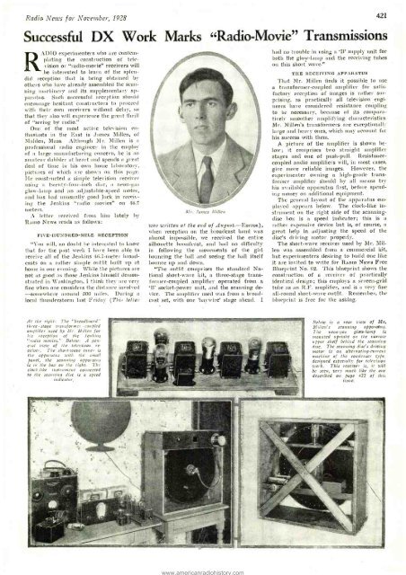
A picture of the amplifier is shown below;<br />
it comprises two straight amplifier<br />
stages and one of push -pull. Resistance -<br />
coupled audio amplifiers will, in most cases,<br />
give more reliable images. However, the<br />
experimenter owning a high -grade transformer<br />
amplifier should by all means try<br />
his available apparatus first, before spending<br />
money on additional equipment.<br />
The general layout of the apparatus employed<br />
appears below. The clock -like instrument<br />
on the right side of the scanning -<br />
disc box is a speed indicator; this is a<br />
rather expensive device but is, of course, a<br />
great help in adjusting the speed of the<br />
disc's driving motor properly.<br />
The short -wave receiver used by Mr. Millen<br />
was assembled from a commercial kit,<br />
but experimenters desiring to build one like<br />
it are invited to write for RADIO News Free<br />
Blueprint No. 62. This blueprint shows the<br />
construction of a receiver of practically<br />
identical design; this employs a screen -grid<br />
tube as an R.F. amplifier, and is a very fine<br />
all -rood short -wave outfit. Remember, the<br />
blueprint is free for the asking.<br />
At the right: The "breadboard"<br />
three -stage transformer - coupled<br />
amplifier used by Mr. Millen for<br />
his reception of the Jenkins<br />
"radio movies." Below: A general<br />
view of the television re.<br />
triver. The short -wave tuner is<br />
the apearatu s with the small<br />
panel, the scanning apparatus<br />
is in the box on Nue right. The<br />
clock -like instrument connected<br />
to the scanting disc is a speed<br />
indicator.<br />
Below is a rear view of Mr.<br />
Jlillen's scanning apparatus.<br />
The neon -.gas glow -lamp is<br />
mounted upright on the narrow<br />
upper shelf behind the scanning<br />
disc. The scanning disc's driving<br />
motor is an alternating -current<br />
machine of the condenser type.<br />
designed especially for television<br />
work. This receiver is, it will<br />
be seen, very much like the one<br />
described on page 422 of this<br />
issue.<br />
i


