

TELEVISION NUMBER - AmericanRadioHistory.Com
TELEVISION NUMBER - AmericanRadioHistory.Com
TELEVISION NUMBER - AmericanRadioHistory.Com

Create successful ePaper yourself
Turn your PDF publications into a flip-book with our unique Google optimized e-Paper software.
www.americanradiohistory.com<br />
434 Radio News for November, 1928<br />
f<br />
j<br />
-<br />
a<br />
eer,,,<br />
9 0<br />
a s New -1 1<br />
ün a<br />
`I f<br />
;<br />
Two -Way Regulator Corrects<br />
Line -Voltage Variation<br />
THE small box -shape device illustrated<br />
in this column is a voltage regulator for<br />
use in connection with radio receivers. It<br />
tential to 110 volts for the operation of<br />
the radio receiver, regardless of whether<br />
the line -voltage is above or below this value;<br />
whereas resistors are capable only of reducing<br />
the voltage. Secondly, the unit<br />
has a sufficiently wide range to cover all<br />
conditions; it will increase the voltage to<br />
normal value from as low as 90 volts, or it<br />
will decrease the voltage to normal from<br />
as high as 130 volts. Thirdly, there are<br />
eight voltage taps, thus providing a ver,v<br />
close adjustment. And fourthly, it is highly<br />
efficient, as it regulates the voltage by reactance,<br />
rather than resistance.<br />
The appearance of the device is clearly<br />
shown in the accompanying picture; it is<br />
housed in a metal box 41/4 x 414 x 3'''%<br />
inches and weighs 3 pounds. It is provided<br />
with a cord and plug for connection<br />
to the lamp socket, and also with a 110 -<br />
volt receptacle for the plug of the power<br />
transformer; the only adjustment is a knob<br />
which operates an eight -point switch.<br />
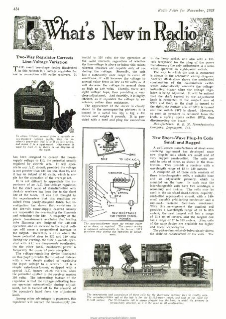
The way in which the unit is connected<br />
is shown in the schematic wiring diagram.<br />
Another illustration shows the mechanical<br />
construction of the combination switch<br />
which automatically connects the voltage -<br />
indicating buzzer when the voltage regulator<br />
is being adjusted. It will be noticed<br />
that the shaft turned by the adjustment<br />
knob is connected to the contact arm of<br />
SW1 and that, as the shaft is turned to<br />
the right, the contact arm of SW1 is turned<br />
and the switch SW2 is closed. However,<br />
as soon as pressure is removed from the<br />
knob, It spring opens switch SW2, thus<br />
disconnecting the buzzer.<br />
Manufacturer: R. B. 3!. Manufacturing<br />
<strong>Com</strong>pany, Logansport, Ind.<br />
To obtain 110 -volt current from a variable or<br />
non -standard lighting supply, plug the receiver's<br />
power -unit lead in at B on this device,<br />
and insert C in a light -socket. Adjustment is<br />
made by knob A, as shown in the diagram at<br />
the right.<br />
has been designed to correct the housesupply<br />
voltage to 110, the potential usually<br />
required by electric sets. It will operate<br />
in any A.C. circuit, provided the voltage<br />
is not greater than 130 nor less than 90, and<br />
it has an output of 60 watts, which is ample<br />
for the operation of the average set.<br />
It is not difficult to appreciate the importance<br />
of an A.C. line -voltage regulator,<br />
for the chief cause of dissatisfaction with<br />
electric receivers has been due to the short<br />
life of the tubes. It was first thought by<br />
the experimenters that this condition resulted<br />
from poorly -designed .tubes, but investigation<br />
has shown that variations in<br />
the 110 -volt house -supply current usually<br />
are responsible for overloading the filaments<br />
and reducing tube life. A. majority of the<br />
power transformers available for heating<br />
tube filaments are designed for 110 -volt<br />
operation and an increase in the input voltage<br />
will cause a proportional increase in<br />
the output. Therefore, in cities where the<br />
house potential rises to 120 and 130 volts<br />
during the evening, the tube filaments operated<br />
with A.C. are dangerously overheated.<br />
On the other hand, insufficient power is<br />
frequently the cause of poor reception.<br />
The voltage- regulating device illustrated<br />
on this page provides the broadcast listener<br />
with a very simple method of regulating<br />
the input voltage to a receiver. It is a<br />
simple auto-transformer, equipped with a<br />
special A.C. buzzer which vibrates when<br />
the potential applied to the receiver reaches<br />
110 volts. The interesting feature of the<br />
regulator is that the voltage- indicating buzzer<br />
operates automatically during adjustment,<br />
but is turned off by the removal of<br />
the operator's hand from the adjustment<br />
knob.<br />
Among other advantages it possesses, this<br />
regulator will correct the house -supply po-<br />
5W 2<br />
VIBRATOR<br />
5W 1<br />
TO 110V. A. C.<br />
SPRING<br />
5W 2<br />
-m41<br />
}<br />
110-V. RECEPTACLE<br />
FOR POWER TRANS-<br />
FORMER.<br />
T he auto -transformer steps the voltage either<br />
up or down, as required. The correct setting<br />
is indicated automatically by the buzzer; SW2<br />
functions only during the operation of adjustment.<br />
New Short -Wave Plug -In Coils<br />
Small and Rugged<br />
A well -known manufacturer of short -wave<br />
receiving equipment has developed some<br />
new plug -in coils which are small and of<br />
very rugged construction. The coils are<br />
sold in sets of three, as shown in the illustration.<br />
They provide a receiver with a<br />
wavelength range of 15 to 130 meters.<br />
A complete set of these coils consists of<br />
three interchangeable coils, a suitable base<br />
and an adjustable primary, which is<br />
mounted on the base. In each case the<br />
interchangeable coils have two windings, a<br />
secondary and tickler. The coils may be<br />
used in the standard fixed- tickler, capacity -<br />
controlled regenerative circuit, with a 140 -<br />
mmf. variable grid -tuning condenser and a<br />
250 -mmf. variable feed -back condenser.<br />
With this arrangement the smallest coil<br />
provides a wavelength range of 15 to 33.5<br />
meters, the next largest coil has a range<br />
of 31.5 to 68 meters, and the largest coil<br />
has a range of 57 to 133 meters. Also, coils<br />
of the same design are available for higher<br />
and lower wavelengths.<br />
The picture immediately below clearly shows<br />
the skeleton construction of the coils. The<br />
The compactness and convenience of these coils for the short -wave operator may be readily seen.<br />
The secondary- tickler coil at the left is for the 15 -33.5 -meter range, and that at the right for<br />
3L5 -68 meters. The 57. 133 -meter coil is shown plugged into the base; to which the primary is<br />
permanently attached, as it is the some in all combinations.


