

TELEVISION NUMBER - AmericanRadioHistory.Com
TELEVISION NUMBER - AmericanRadioHistory.Com
TELEVISION NUMBER - AmericanRadioHistory.Com

You also want an ePaper? Increase the reach of your titles
YUMPU automatically turns print PDFs into web optimized ePapers that Google loves.
www.americanradiohistory.com<br />
Radio News for November, 1928 423<br />
TO PLATE OF<br />
DETECTOR e<br />
TUBE 'I<br />
R1<br />
TO "B'+<br />
DETECTOR<br />
R3<br />
0<br />
V1 V2 V3<br />
-<br />
R3<br />
al<br />
r .ig<br />
-<br />
R4<br />
F<br />
i<br />
eL2<br />
II o 0<br />
o o<br />
180 -VOLT<br />
"B" BATTERY<br />
_L<br />
R5<br />
NEON<br />
TUBE<br />
DISC<br />
MOTOR<br />
R6<br />
SWITCH<br />
SWITCH 1 MF.<br />
DOUBLE -<br />
CIRCUIT JACK<br />
R7<br />
- + B- C+ C- C- B--<br />
A 1 -3 40 180<br />
VOLTS VOLTS VOLTS<br />
FIG. 1<br />
110 VOLTS<br />
A. C.<br />
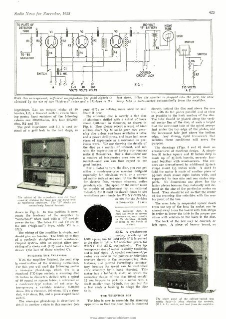
Vitte this arrangement, sufficient amplification for good signals is<br />
obtained by the use of two "high -inn" tubes and a 171 -type in the<br />
last stalle. When the speaker is plugged into the jack, the neonlamp<br />
tube is disconnected automatically from the amplifier.<br />
impedance, LI; an output choke of 30<br />
henries, L2; a filament switch; eleven binding<br />
posts; fixed resistors of the following<br />
values: one 100,000 -ohm, R1; four 250,000 -<br />
ohm, 112 and 113.<br />
The grid impedance unit LI is used instead<br />
of a grid Irak in the last stage, as<br />
The cabinet of the reproducer with the front<br />
removed, showing the lamp and the motor with<br />
its regulating condenser. The "B" blocks are<br />
conveniently located beneath.<br />
shown in Fig. 1. In this position it overcomes<br />
the tendency of the amplifier to<br />
"motorboat" when used with a "B" socket -<br />
power device. The tubes Vi and V2 are of<br />
the 240 ("high-mu") type, while V3 is a<br />
171A.<br />
The wiring of the amplifier is simple, and<br />
should give no trouble. The hook -up is that<br />
of a perfectly straightforward resistance -<br />
coupled system, with an output filter consisting<br />
of a choke coil (1.2) and a fixed condenser<br />
(the last of those marked C).<br />
BUILDING THE TELEVISOR<br />
With the amplifier finished, the next step<br />
is construction of the scanning mechanism..<br />
For this you will need the following parts:<br />
a neon -gas glow -lamp, which fits in a<br />
standard UX -type socket; a scanning disc<br />
24 inches in diameter, drilled with a spiral<br />
of 48 round or square holes; a universal or<br />
a condenser-type motor, of not over 1/8_<br />
horsepower; a variable resistor, 0- 10,000<br />
ohms, I15; a rheostat, 100 ohms, Rî; a rheostat,<br />
0 -10 ohms, R6, and a pear -shaped hand<br />
switch.<br />
The neon -gas glow -lamp is described in<br />
detail in another article in this number (see<br />
page 427) ; so nothing more need be said<br />
about it here.<br />
The scanning disc is merely a flat disc<br />
of aluminum drilled with a spiral of holes<br />
about 3/64 -inch in diameter, as shown in<br />
Fig. 4. Now please accept a word of kind<br />
advice: don't try to make your own scanning<br />
disc unless you have available a lathe<br />
and a power drill- press, and have had some<br />
years of experience as a mechanic on precision<br />
work. We are showing the details of<br />
the disc as a matter of interest, and not<br />
with the expectation of having our readers<br />
make it themselves. Buy a disc -there are<br />
a number of inexpensive ones now on the<br />
market -and you can then expect to see<br />
good images.<br />
For a motor to turn the disc, you can get<br />
either a condenser -type machine designed<br />
especially for television work, or a universal<br />
motor such as are used by the thousands<br />
for electric fans, vacuum cleaners, coffee<br />
grinders, etc. The speed of the motor must<br />
be capable of adjustment by an external<br />
rheostat; for it must be slowed down to 450<br />
revolutions per minute for WRNY- W2XAL,<br />
or 900 for the Jenkins<br />
radio -movies f r o m<br />
The scanning disc, to<br />
show the image in correct<br />
arrangement, must revolve<br />
in the direction opposite<br />
to those of the hands of<br />
a clock.<br />
3XK. A synchronous<br />
motor, revolving at<br />
1,800 r.p.m., can be used only if it is geared<br />
to the disc by 1 :1 or 1':2 reduction gears, for<br />
WRNY and 3XK, respectively. The 1/4-<br />
horsepower size of motor is widely available,<br />
and is just` right. A special condenser -type<br />
motor was used in the particular television<br />
receiver shown in the accompanying illustrations,<br />
and proved exceedingly satisfactory<br />
because its speed can be controlled<br />
very smoothly by a hand rheostat. 'l'liis<br />
motor has a half -inch shaft, on which the<br />
Mounting flange of the disc fitted snugly.<br />
If you happen to pick up a motor with a<br />
shaft smaller than IA-inch, you can buy for<br />
a few cents a bushing to adapt the disc<br />
to it.<br />
THE TELEVISOR BOX<br />
The idea is now to assemble the scanning<br />
apparatus so that the neon tube is mounted<br />
directly behind the disc and above the motor,<br />
with its flat plates parallel and as close<br />
as possible to the back surface of the disc.<br />
The tube should be placed along the vertical<br />
center line of the disc, at such a height<br />
that the outermost hole of the spiral sweeps<br />
,just under the top edge of the plates, and<br />
the innermost hole just above the bottom<br />
edge. Any strong, rigid framework that<br />
satisfies these conditions will serve the<br />
purpose.<br />
The drawings (Figs. 5 and 6) show an<br />
arrangement of excellent design. A simpb<br />
box 31 inches square and 12 inches deep k<br />
made up of 3/4-inch boards, securely fastened<br />
together with wood- screws. The corners<br />
are strengthened by additional 3 -inch<br />
strips about l/ inches wide. A shelf to<br />
'hold the motor is made of another piece of<br />
3 -inch stock about eight inches wide, and<br />
supported by two side and one center supports.<br />
No dimensions are given for the<br />
latter pieces because they naturally will depend<br />
on the size of the particular motor on<br />
hand.<br />
They should be cut so that the center<br />
of the scanning disc coincides with the center<br />
point of the box.<br />
The neon tube is suspended upside döwn<br />
from the top cf the box; its socket can lie<br />
spaced away trom the board with thin strips<br />
in order to lower the tube to the proper position<br />
with relation to the holes in the disc.<br />
The back of the box may be covered, or<br />
left open. A piece of beaver board, or<br />
The lower panel of the cabinet -which was<br />
solidly built -i,, place showing the controls,<br />
(R 5, 6, 7), switch, and lead from tue amplifier.


