

TELEVISION NUMBER - AmericanRadioHistory.Com
TELEVISION NUMBER - AmericanRadioHistory.Com
TELEVISION NUMBER - AmericanRadioHistory.Com

You also want an ePaper? Increase the reach of your titles
YUMPU automatically turns print PDFs into web optimized ePapers that Google loves.
www.americanradiohistory.com<br />
460<br />
Radio News for November, 1928<br />
LAB(RATORCE<br />
e rneltsnco<br />
adïo News<br />
praforie5<br />
manufacturers arc invited to send to RADIO NEWS LABORATORIES<br />
RADIO samples of their products for test. It does not matter whether or not<br />
they advertise in RADIO NEWS, the RADIO NEWS LABORATORIES being an independent<br />
organisation, with the improvement of radio apparatus as its aim.<br />
/f, after being tested, the instruments submitted prove to be built according<br />
ro modern radio engineering practice, they will each be awarded a certificate<br />
cf merit; and that apparatus which embodies novel, as well as meritorious<br />
features in design and operation, will be described in this department, or in<br />
the "What's New in Radio" department, as its news value and general interest<br />
for our readers shall deserve. If the apparatus does not pass the Laboratory<br />
tests, it will he returned to the manufacturer with suggestions for improve.<br />
meats. No "write-ups" sent by manufacturers are published in these pages,<br />
and only apparatus which has been-tested in the Laboratories and found of<br />
good mechanical and electrical construction is given a certificate. As the sere -<br />
vice of the RADIO NEWS LABORATORIES is free to all manufacturers, whether<br />
they are advertisers or not, it is necessary that all goods to be tested be forwarded<br />
prepaid, otherwise they cannot be accepted. Apparatus ready for, or<br />
already on, the market will be tested for manufacturers free of charge. Apparatus<br />
in process of development will be tested at a charge of $2.00 per hour<br />
required to do the work. Address all communications and all parcels to RADIO<br />
NEWS LABORATORIES, 230 Fifth Avenue. New York City. Readers will be informed<br />
on request if any article has been issued a Certificate of Merit.<br />
AUDIO -FREQUENCY<br />
TRANSFORMER<br />
The "Type AX" audio -frequency<br />
transformer shown, submitted by the<br />
Sangamo Electric <strong>Com</strong>pany, Springfield,<br />
III., is of excellent mechanical<br />
and electrical design. The amplification<br />
of the transformer maintained<br />
a value almost constant from 32 to<br />
5,000 cycles, when used with the<br />
201A -type tube. The primary in-<br />
ductance, with a<br />
plate current of<br />
3 milliamperes, was found to be<br />
approximately 80 henries. The<br />
transformer has a ratio of three to<br />
rie; and excellent quality with great<br />
volume was obtained when it was<br />
used in the conventional audio am-<br />
plifier employing the 201A and 171<br />
tubes. The transformer is identified<br />
by a yellow spot. The core and<br />
winding are completely shielded by<br />
an iron housing of olive -green finish.<br />
The dimensions of the base are 2%<br />
x 2h inches, while the height is 3<br />
inches.<br />
AWARDED TI1E R. \DIO NEWS<br />
LABORATORIES CERTIFICATE<br />
OF MERIT NO. 2421.<br />
AUDIO -FREQUENCY CHOKE<br />
The "Type E" audio- frequency<br />
choke or "impedance" submitted by<br />
the same manufacturer, is of the<br />
same size and shape as their "Type<br />
AX" A.F. transformer illustrated<br />
above. It is used as an output impedance<br />
for the 171 -type power tube.<br />
in which case the entire inductance<br />
is employed.<br />
It may he used also<br />
as an output impedance for the 112 -<br />
or 210 -type power tubes, by using<br />
the portion of the winding between<br />
"T" and "B } "' It is designed to<br />
match the impedance of the modern<br />
power tubes and, for this reason,<br />
allows the lower frequencies to be<br />
better reproduced. When it is emrloyed<br />
in the output circuit, a blocking<br />
condenser external to the choke<br />
must also be used; this should have<br />
f rom 2 to 4 tuf. capacity, and be<br />
of voltage rating suitable to withstand<br />
safely the maximum voltage<br />
of the power stage. The inductance<br />
was found to be within 10% of<br />
the rated value of 30 henries, when<br />
measured at 60 cycles; the ohmic<br />
resistance is approximately 570. The<br />
metal case is finished in dark red<br />
and the device is identified by a<br />
"mandarin red "' spot.<br />
AWARDED THE RADIO NEWS<br />
LABORATORIES CERTIFICATE<br />
OF MERIT NO. 2422.<br />
AC- OPERATED RECEIVER<br />
The "Packard" 8 -tube radio receiver<br />
shown, submitted by the Packard<br />
Radio Co., 2161 No. California<br />
Ave., Chicago, Ill., is of the all -<br />
electric type, using five 226 A.C.<br />
tubes, one 227 A.C. (heatéd- cathode)<br />
detector tube, and two 171 power<br />
tubes; it operates directly from the<br />
110 -volt, 60- cycle, house- lighting circuit.<br />
The low -voltage A.C. current<br />
for the filaments of the tubes is<br />
supplied by separate windings of the<br />
power transformer, and the "B"<br />
voltages are provided by a full -wave<br />
rectifier of the 280 type in connection<br />
with an efficient filter system,<br />
the chokes of which are contained<br />
in the same metal housing with the<br />
power transformer. Three stages of<br />
tuned radio frequency of modern design,<br />
using 226 -type tubes, give ample<br />
selectivity and sensitivity. The<br />
tuning inductors are of the compact,<br />
small -field type, enclosed in indi-<br />
vidual shield cans. The radio -frequency<br />
stages are followed by a<br />
conventional 227 -type detector, which<br />
feeds into two stages of transformer -<br />
coupled (1:1 ratio) audio frequency,<br />
followed by a stage of push -pull<br />
power amplification of the 171 type.<br />
The speaker windings are protected<br />
by a balanced output choke. The<br />
tuning of the R.F. and detector circuits<br />
is accomplished by one control,<br />
which is .geared to the common shaft<br />
of the condenser rotors; the scale is<br />
of the drum type. A fine adjustment<br />
of tuning for DX work is accomplished<br />
by means of the levers protruding<br />
through the panel on each<br />
side of the tuning control. A power<br />
rheostat with a panel voltmeter is<br />
provided. to maintain the filaments<br />
of the tubes at the proper temperature.<br />
The control at the right of<br />
the set is provided for controlling<br />
oscillations and volume, and there is<br />
a sub -panel adjustment to balance<br />
out the hum in the R.F. and 1:1-<br />
ratio audio stages. The filament<br />
circuits of the detector and the<br />
power tubes are automatically balanced<br />
by center- tapped windings. The<br />
receiver is of attractive appearance,<br />
and its operation, with regard to<br />
sensitivity, selectivity, quality, volume,<br />
and elimination of the A.C.<br />
bum, is satisfactory.<br />
AWARDED THE RADIO NEWS<br />
LABORATORIES CERTIFICATE<br />
OF MERIT NO. 2423.<br />
PHONOGRAPH PICK -UP<br />
The "Via-Rad" phonograph pick-up<br />
device shown, submitted by the<br />
Brooklyn Metal Stamping Corp.,<br />
718-728 Atlantic Ave., Brooklyn,<br />
N. Y., is of the magnetic type and<br />
makes it possible to reproduce speech<br />
and music from ordinary phonograph<br />
records, when it is used in connection<br />
with an audio -frequency amplifier.<br />
It is of the balanced- armature<br />
type; the airgap between the pole<br />
pieces is adjusted in the factory before<br />
sealing. The magnets are of<br />
the bar type and situated on each<br />
side of the adjustable pole pieces<br />
in such positions that their fields<br />
assist. Their magnetic strength is<br />
great, resulting in a very sensitive<br />
and loud reproducer. The frame or<br />
base which supports the coil, armature,<br />
and pole pieces, the dimensions<br />
of which are 11/4 x 2 inches, is cast<br />
of aluminum alloy. The end of the<br />
balanced armature protrudes through<br />
the metal housing and carries at its<br />
end the socket and fastening screw<br />
for the phonograph needle. The device<br />
is fitted with a flange, designed<br />
to fasten over the tone arm<br />
of the phonograph after the usual<br />
reproducer has been removed. The<br />
over -all dimensions are 2j inches<br />
long, 2 inches wide, and 1g inches<br />
high; and the weight 8 ounces. The<br />
housing is of a gold - finish.<br />
AWARDED THE RADIO NEWS<br />
LABORATORIES CERTIFICATE<br />
OF MERIT NO. 2424.<br />
PICK -UP VOLUME CONTROL<br />
The "Via-Trot" phonograph pickup<br />
device volume control shown, submitted<br />
by the same manufacturer,<br />
is of the graphite -and -powdered-mica<br />
compression type; it has a resistance<br />
range from 0 to 500,000 ohms and<br />
is to be shunted across the terminals<br />
of the phonograph pick -up device.<br />
This resistor is provided with cord -<br />
tip jacks, two on each side of the<br />
housing; the tips of the pick -up are<br />
plugged into one pair of jacks, while<br />
those of the receiving -set adaptor<br />
are plugged into the other pair. The<br />
case or housing is of brown molded<br />
bakelite of pleasing appearance, the<br />
top is of gold- finished die -stamped<br />
metal, and the adjusting knob is<br />
molded of the same colored bakelite.<br />
The diameter of the base is 21/4<br />
inches and the height over all 2V<br />
inches. The device has proved satisfactory<br />
in giving smooth control of<br />
volume when used with the pick -up<br />
manufactured by the same concern.<br />
AWARDED THE RADIO NEWS<br />
LABORATORIES CERTIFICATE<br />
OF MERIT NO. 2425.<br />
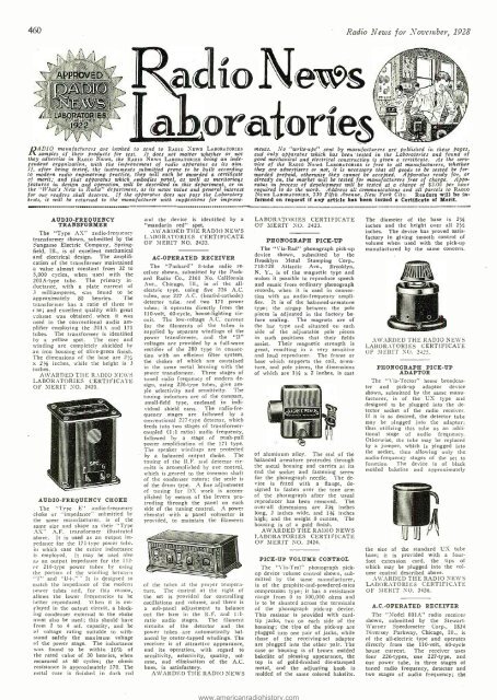
PHONOGRAPH PICK -UP<br />
ADAPTOR<br />
The "Via-Tector" home broadcaster<br />
and pick-up adaptor device<br />
shown, submitted by the same manufacturer,<br />
is of the UX type and<br />
designed to be plugged into the detector<br />
socket of the radio receiver.<br />
If it is so desired, the detector tube<br />
may be plugged into the adaptor;<br />
thus utilizing this tube as an additional<br />
stage of audio frequency.<br />
Otherwise, the tube may be replaced<br />
by a jumper, which is plugged into<br />
the socket, thus allowing only the<br />
audio -frequency stages of the set to<br />
function. The device is of black<br />
molded bakelite and approximately<br />
the size of the standard UX tube<br />
base; it is provided with a four -<br />
foot extension cord, the tips of<br />
which may be plugged into the volume<br />
control described above.<br />
AWARDED THE RADIO NEWS<br />
LABORATORIES CERTIFICATE<br />
OF MERIT NO. 2426.<br />
A.C.-OPERATED RECEIVER<br />
The "Model 801A" radio receiver<br />
shown, submitted by the Stewart -<br />
Warner Speedometer Corp., 1834<br />
Diversey Parkway, Chicago, Ill., is<br />
of the all- electric type and operates<br />
directly from the 110 -volt, 60 -cycle<br />
house current. The receiver uses<br />
four 226- types, one 227 -type, and<br />
one power tube, in three stages of<br />
tuned radio frequency, detector and<br />
two stages of audio frequency; the


