

TELEVISION NUMBER - AmericanRadioHistory.Com
TELEVISION NUMBER - AmericanRadioHistory.Com
TELEVISION NUMBER - AmericanRadioHistory.Com

You also want an ePaper? Increase the reach of your titles
YUMPU automatically turns print PDFs into web optimized ePapers that Google loves.
www.americanradiohistory.com<br />
Radio News for November, 1928 459<br />
SET BUILDING IN FRANCE<br />
Editor, RADIO NEWS:<br />
Just a few lines of appreciation to yourself and<br />
RADIO NEWS, the current copy of which was a<br />
boon companion to me during an exceedingly violent<br />
electrical storm up here (at Holzleck, in the<br />
Vosges Mountains). I was far too deeply engrossed<br />
in your description of the Screen -Grid Strobodyne<br />
to notice such trifles as storms. I ha n<br />
taken RADIO NEWS since its first edition but, because<br />
of traveling all over the world, I had to<br />
plan with my newsdealer in New York to hold<br />
over my copies until my return. Now that I have<br />
a permanent address in Paris, I have at last become<br />
a subscriber.<br />
Here is something that would be of great assistance<br />
to me and undoubtedly to many other<br />
fans over here, and that is a table comuaring the<br />
relative sizes of wires between the American B & S<br />
gauge and the French gauge which is given in<br />
mils. I desire to build a Strobodyne a l' Americaine,<br />
but cannot do so until I know what size<br />
wire is equivalent to that given. (See below). I<br />
fell down on the construction of the RADIO News<br />
Short -Wave set on this account and am anxious<br />
to complete it and fish for good old \VRXY on<br />
the 30.91 -meter wave.<br />
We have not yet come to the screen -grid tube<br />
in France, but I have found that the "Metal<br />
Radio" factories are putting one on the market<br />
in the near future, and if it has similar characteristics<br />
to the 222, I shall build the Strobodyne<br />
S. G. as described.<br />
I am at present using a Strobodyne built by M.<br />
Chrétien, the originator of the circuit, but the<br />
American hook -up is way ahead of it. My set<br />
has coils for both wavebands (180 to 500 and 500<br />
to 3.000 meters) incorporated, and the change is<br />
made by a commutator on the panel.<br />
By the way, the relay of the Tunney- Ilceney<br />
fight over Daventry and 21.0 was wonderful. I<br />
received it in Paris clear as a bell. Absolutely<br />
no fading right up to R'GY's announcement of<br />
the time signal, when England acknowledged the<br />
defeat of her champion with silence immediate and<br />
profound. But that relay certainly spoke worlds<br />
of the future of radio from an international view -<br />
point; may good old RADIO NEWS stick and grow<br />
with it..<br />
R. W. HuMPHRE.YS,<br />
57 Boulevard Suchet, Paris 16e, France<br />
Metric Measurements of Wire<br />
( Fiere arc the measurements of copper wire -<br />
the metal conductor only -in the metric system: the<br />
diameter in millimeters and the area in square<br />
millimeters. This may be of benefit to some of<br />
our other friends abroad. The gauge is Use familiar<br />
American Brown & Sharpe.- Eotroa.)<br />
Gauge Diam. Area Gauge Diam. Area<br />
14 1.628 2.081 28 0.321 0.081<br />
16 1.291 1.309 30 0.255 0.051<br />
18 1.024 0.823 32 0.202 0.032<br />
20 0.812 0.513 34 0.160 0.020<br />
22 0.644 0.325 36 0.127 0.013<br />
24 0.511 0.205 38 0.101 0.008<br />
26 0.405 0.123 40 0.080 0.005<br />
NO PANCAKES FOR BREAKFAST<br />
Editor, RADIO NEWS:<br />
I attach a snapshot of two speakers made of<br />
scrap paper, a cone and a horn built along the<br />
lines of the model described in Chester Schenck's<br />
article in the June issue of RADIO NEWS. The<br />
horn was built around a form made from an old<br />
orange crate and some stiff cardboard; the forni<br />
Mr. Ste-wart, above, flanked on either side by<br />
a low -cost loud speaker made as described.<br />
It will be bard to lower his record unless you<br />
steal a unit.<br />
being well coated with talcum powder to insure<br />
its easy removal after the horn had thoroughly<br />
dried. For the material, I used all the old magazines,<br />
newspapers, wrapping paper and so forth<br />
that was available, and for paste a mixture of flour<br />
and water. The job was rather tedious; but, as<br />
L am not especially fond of work anyway, it came<br />
in handy to apply a layer or two a day and allow<br />
time for drying. The horn was finally built up to<br />
near / -inch in thickness, but is still too thin. Only<br />
one brace is used, that being made of four pieces<br />
of wood, )1 -inch square and about twelve inches<br />
long, nailed together in the form of a square and<br />
slipped down on the bell as far as it will go and<br />
pasted in position. The tone is as good as that of<br />
several manufactured horns I've heard, and better<br />
than some.<br />
The cotte consists of one layer of heavy brown<br />
wrapping paper with two layers of newspapers<br />
pasted on the outside, three layers in all. A circle<br />
36 inches in diameter was laid off out this and a<br />
V- shaped slice cut out. That gave me a cone 34<br />
inches in diameter and 7 inches deep. A loop of<br />
soft copper wire was pasted on the outer edge and<br />
the string used for mounting the cone in the<br />
square wooden framework was laced back and forth<br />
through the wire and to the frame. A 1 x 2<br />
bolted to the frame, supports a cigar box, which,<br />
in turn. supports the driving unit, one taken from<br />
a Musicone. The main item of expense in this big<br />
cone was five cents for the two bolts in the 1 x 2;<br />
the flour for the paste was stolen from the family<br />
larder, so cost nothing.<br />
The cone is by far the better of the two. Both<br />
reproduce well the bass and middle- register notes;<br />
but we have lots of static down in this hot country<br />
and it is not so objectionable on the cone as on<br />
the horn. The set driving these speakers is home -<br />
built, a Browning -Drake type, with a screen -grid<br />
R.F. stage, 200A detector, Thordarson Autoformer<br />
audio amplifier with a UX -112 in the last socket.<br />
\ olume amt quality de luxe!<br />
GtY STEWART,<br />
U opio, Texas.<br />
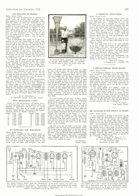
A SENSITIVE FOUR -TUBER<br />
Editor, RADIO NED S:<br />
I am sending my four -tube circuit, which was<br />
very much like Mr. McCormick's till the screen -<br />
grid tube came out. I think that the only real<br />
difference was that I changed my antenna coil<br />
by doing away with the fixed condenser and tapping<br />
at the twelfth turn from the filament end. 1<br />
have written Mr. McCormick, advis'ng him to put<br />
a screen -grid tube in his R.F. stage; it requires<br />
only a little changing and it is well worth the<br />
trouble. With his DX record, using a 201A, he<br />
certainly should step out with the screen -grid hookup<br />
for a few more miles.<br />
This circuit is very sensitive and selective with<br />
a short antenna, and the west coast comes in with<br />
plenty of volume.<br />
We have only from 7:30 p. m. until midnight<br />
to do any DXing, on account of the high -power<br />
naval station NSS here, which sends off a heavy<br />
mush or "back- wash "; so you can see ive do not<br />
have a shot at the foreigners. My most distant<br />
stations are California, Mexico, Cuba and Canada;<br />
but remember we have to do this early.<br />
This circuit was originally the "Reactodyne" published<br />
by RADIO NEWS its 1924. I hope you can<br />
interest a few others in this circuit.<br />
FRANCIS E. ENGLE,<br />
14 Cathedral St., Annapolis, .l(d.<br />
A SINGLE- CONTROL SHORT -WAVER<br />
Editor, RADIO NEws:<br />
I am enclosing a diagram of a "one-hand" shortwave<br />
receiver I have been using for about four<br />
months. I use Aero short -wave coils; with this<br />
arrangement I am able to set the feed -back control<br />
condenser for a given coil and sweep th,s whole<br />
range without any other adjustment until the desired<br />
signal is found. Then a little adjustment of<br />
the detector filament and I am all set to listen.<br />
No more "holes," etc.<br />
I am using special R.F. chokes. \\'hile an<br />
Aero No. 10 will work very well, a choke with very<br />
low inductance must be used on S. W. I use No.<br />
36 S.C.C. on a piece of round or square Vs -inch<br />
bakelite, about 6 inches long; start winding otoz<br />
end about 40 turns, space %-inch, then 60 turns,<br />
space 1/s -inch, 80 turns, and so on till the space is<br />
used up. I find the 112A tube the best detector<br />
for this receiver; the rest is standard.<br />
W. E. SMITH,<br />
Oak Forest, Illinois.<br />
MR. LOVELESS IS NOT SOLELY TO BLAME<br />
Editor, RADIO NEWS:<br />
I was interested in finding in the article on the<br />
Loveless aerial the description of a circuit embodying<br />
the principle of my patent No. 1,668,261,<br />
issued to me by the patent office May 1, 1928;<br />
application for the same having been filed Dec. 27,<br />
1923. An examination of this patent will reveal<br />
the validity of my claim; for it will be there seen<br />
that specific claim is there made for aerial circuits<br />
together with a claim embodying the same principle<br />
in radio sets themselves. The discovery of the<br />
principle involved was made by me as far back<br />
as 1920, while engaged as professor of physics its<br />
the University of Santa Clara.<br />
(Rev.) RICHARD H. BELL, S. J.<br />
St. Ignatius College, 2130 Fulton St.,<br />
San Francisco, Calif.<br />
(Continued on page 498)<br />
47<br />
22D LC<br />
i j<br />
i j<br />
35T 47T<br />
26D.CC. 22 D.C[<br />
2zz ¡ 2OI-A 201-A<br />
h<br />
,<br />
_<br />
FiY<br />
áó<br />
°°fiV<br />
71-A<br />
Ir<br />
-.00015 MMF<br />
r<br />
- I I 2-A<br />
t<br />
b<br />
BND, A- C4 -A +B=<br />
O 6<br />
B+45v. 'C=4;V. '8". 90V. -C-27V. '8+135V.<br />
Mr. Engle's hook -up differs from the " Reactodyne" in its aerial circuit; the latter was<br />
very loosely coupled in the original. The primaries are wound fumble -fashion and placed<br />
inside the secondaries, which are on 3 -inch tubing. Transformers are 5.31 220s. Ile<br />
suggest a fixed ballast also in the 222's "A-."<br />
Mr. Smith's set is tot a reflex, as first glance might suggest,<br />
but a short -waver with two A.F. amplification stages.<br />
Our readers may test it to see if ease of operation is accompanied<br />
by necessary sensitivity and control.


