

TELEVISION NUMBER - AmericanRadioHistory.Com
TELEVISION NUMBER - AmericanRadioHistory.Com
TELEVISION NUMBER - AmericanRadioHistory.Com

Create successful ePaper yourself
Turn your PDF publications into a flip-book with our unique Google optimized e-Paper software.
www.americanradiohistory.com<br />
Radio News for November, 1928 427<br />
The Neon Tube Television's "Loud Speaker"<br />
How This Marvelous Device Makes Possible the Distant Reproduction<br />
of Moving Scenes Simultaneously with Their Occurrence<br />
0<br />
NE of the essential components of<br />
a television receiver is the glow -<br />
lamp; this and its associated scanning<br />
device serve the sane purpose<br />
in the television apparatus that the loud<br />
speaker serves in the radio set.<br />
This remarkable device, as most success -<br />
fully developed, utilizes neon gas as the<br />
luminous element, and is the only lamp yet<br />
known which, without prohibitive cost, can<br />
be made, satisfactorily, to meet the requirements<br />
of the present television systems; in<br />
which there is required a light -source, of<br />
uniform intensity over a large area, which<br />
will instantaneously vary in brilliancy with<br />
variations in the television signals. The<br />
television lamp most strikingly differs from<br />
the familiar electric lamp, in that it gives<br />
off a soft orange "glow" from a large surface<br />
which may be looked at without hurting<br />
the eyes, rather than the dazzling white<br />
"spot" of an incandescent tungsten filament.<br />
The color of this glow may be readily controlled<br />
in manufacture by variation in the<br />
kind and quantity of gas employed within<br />
the bulb.<br />
As will be seen from Fig. 1, the construction<br />
of the television lamp is apparently<br />
quite simple; although this simplified appearance<br />
has been secured only after a<br />
great deal of research work with gaseous -<br />
conduction tubes and neon lamps of all<br />
types and for many different uses. Indeed,<br />
the development and refinement of this<br />
device has involved a review of many rare<br />
gases, a deep study of atomic structure,<br />
and a long process of reasoning out the<br />
acrobatics of electrons. The highly intricate<br />
action taking place in the miniature universe<br />
of the gas contained in the television lamp<br />
is, therefore, not at all in keeping with<br />
the utter simplicity of the mechanism and<br />
electrical features of the device; yet we<br />
must master the first before we can enjoy<br />
the second.<br />
ITS ACTION A PARADOX<br />
The "glow" takes place uniformly over<br />
the surface of either one or the other of<br />
the two flat and parallel plates (P and PI,<br />
Fig. 1) ; the effect depending upon which<br />
plate is connected to the positive and which<br />
to the negative side of the power supply.<br />
The two parallel plates are so placed with<br />
respect to each other as toT utilize the principle<br />
of "short- path'-insulation in order<br />
to prevent "glow" between the plates which,<br />
of course, would not be very desirable.<br />
The "short- path" prinçiple is one of<br />
those scientific truths that are stranger than<br />
fiction. Briefly, in a gaseous conducting<br />
nteditms, if we have oppositely -charged<br />
metallic bodies of sufficiently high potential<br />
difference, the gas between will "break<br />
down" or "ionize," and conduction will take<br />
place from one to the other. However,<br />
move these same conductors very close to<br />
each other, and the gas between is no<br />
longer ionized; Which is apparent from the<br />
fact that there is no longer a glow present<br />
in the tube. Current ceases to flow from<br />
" Raytheon Manufacturing <strong>Com</strong>pany<br />
By D. E. Replogle<br />
one to the other. An excellent insulator is<br />
now presented by the intervening gas. Why?<br />
The explanation is steeped in academic<br />
science, which is usually far beyond the<br />
realm of the layman. Furthermore, no one<br />
has ever seen atoms or electrons; hence cold<br />
logic steps in to explain things which man<br />
may never see for himself. However, if<br />
we may be permitted to make a free translation<br />
into lay language, of a theory by<br />
C. G. Smith, inventor of the "S" tube, the<br />
story runs about like this:<br />
The facing charges of electricity are<br />
bound to produce action. Some loose electron<br />
in the gap between the charged conductors<br />
is coaxed toward one or the other,<br />
and rapidly accelerates its rate of travel<br />
until its speed is sufficient to smash those<br />
atoms obstructing its path. The collisions<br />
result in ionization, or the breaking down<br />
of the gas, which then becomes a fair conductor<br />
of electricity; or, to put it another<br />
way, there is now a wholesale movement<br />
of electrons. It is evident, then, that the<br />
electron needs a good running start, so to<br />
speak, in order to smash things up in<br />
general. Failing in a good running start,<br />
the electron does no smashing, ionization<br />
cannot take place, and there is no electrical<br />
conduction; the gas, under such circumstances<br />
is a good insulator. Some gases<br />
require a longer path for ionization than<br />
others, which is another important consideration.<br />
Helium is especially ideal in<br />
this respect, having an exceptionally long<br />
free path.<br />
CONSTRUCTION OF THE GLOW LAMP<br />
The "short- path" principle, then, is<br />
adopted merely to prevent electrons from<br />
getting a gtiod running start; it is practically<br />
applied in insulating the inner surfaces<br />
of the two electrode plates most effectively.<br />
-<br />
Glass spacers are arranged at the top -<br />
edge of the plates in order to maintain this<br />
separation at just the right value, while the<br />
supporting rods between the stem and the<br />
lower edges of the plates serve the same<br />
purpose at the bottom. The cross rod at<br />
the top of the plates is merely to prevent<br />
the plates from being bent away from their<br />
normal vertical plane, as a result of jars<br />
during transportation. This brace serves<br />
also to prevent vibration of.the plates when<br />
the tube is mounted on the sanie framework<br />
as the scanning -disc motor, as frequently is<br />
the case.<br />
The bull) surrounding the two plates is<br />
of particularly clear glass, to permit the<br />
radiation of the maximum amount of light.<br />
'fhe tube contains neon gas, at a low pressure,<br />
together with certain alkaline substances<br />
which increase the speed of operation<br />
imd the intensity of illumination.<br />
The tube is fitted with a standard UX<br />
base. The luminous plates are placed in a<br />
plane at right angles to the axis of the<br />
socket pin. In a television receiver, therefore,<br />
the pin should point directly either to<br />
or away from the scanning disc, in order<br />
that the glow -lamp's plates may be parallel<br />
to the disc. Connections are made to the<br />
plate, and one of the filament, prongs of the<br />
socket.<br />
CIRCUIT CHARACTERISTICS<br />
As with all types of gas -discharge tubes,<br />
the neon lamp has a very pronounced "negative-<br />
resistance" characteristic and a stabilizing<br />
resistor must always be used in series<br />
with the lamp and the supply voltages.<br />
(This is just a technical way of saying that<br />
the internal electrical resistance of the lamp<br />
decreases as the current through the lamp<br />
is increased. Thus, if no current -limiting<br />
resistor were to be used in series with the<br />
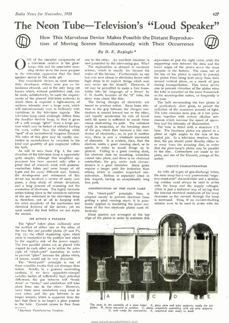
The steps in the assembly of a glow lamp: A, glass stem and wire supports, ready for the<br />
plates. B, plates mounted in position. C, plates completely assembled, with top wire supports.<br />
D, tube ready for evacuation. E, completed tube ready to work.


