

TELEVISION NUMBER - AmericanRadioHistory.Com
TELEVISION NUMBER - AmericanRadioHistory.Com
TELEVISION NUMBER - AmericanRadioHistory.Com

Create successful ePaper yourself
Turn your PDF publications into a flip-book with our unique Google optimized e-Paper software.
www.americanradiohistory.com<br />
Radio News for November, 1928<br />
á<br />
e<br />
6 y~j<br />
ó<br />
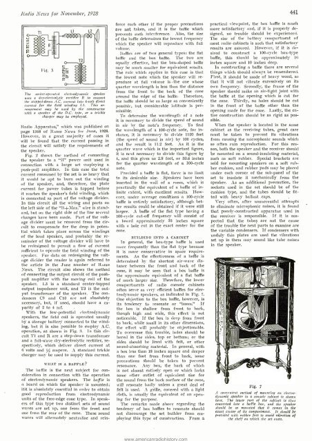
The socket- operated electrodynamic speaker<br />
uses a dry -electrolytic rectifier R to convert<br />
the stepped -dawn A.C. current into 6 -volt direct<br />
current for the field winding LI. This arrangement<br />
may he used by the constructor<br />
with a speaker of the D.C. type, or a trickle<br />
charger may be employed.<br />
Radio Apparatus," which was published on<br />
page 1348 of RADIO NEWS for June, 1928.<br />
However, in a great majority of cases it<br />
will be found that the current passing in<br />
the circuit will satisfy the requirements of<br />
the speaker.<br />
Fig. 2 shows the method of connecting<br />
the speaker to a "B" power unit used in<br />
connection with a large set employing a<br />
push -pull amplifier. In this case the total<br />
current consumed by the set is so heavy that<br />
it would be apt to burn out the winding<br />
of the speaker, and, therefore, the plate<br />
current for power tubes is tapped before<br />
it reaches the speaker's field winding, which<br />
is connected as part of the voltage divider.<br />
In this circuit all the wiring and parts on<br />
the left side of the "13 +JIax." wire is standard,<br />
but on the right side of the line several<br />
changes have been made. Part of the voltage<br />
divider must be removed from the circuit<br />
to compensate for the drop in potential<br />
which takes place across the windings<br />
of the loud speaker, and probably the remainder<br />
of the voltage divider will have to<br />
he redesigned to permit a flow of current<br />
sufficient to operate the field winding of the<br />
speaker. For data on redesigning the voltage<br />
divider the reader is again referred to<br />
the article in the June number of RADIO<br />
NEWS. The circuit also shows the method<br />
of connecting the output circuit of the push-.<br />
pull amplifier with the moving coil of the<br />
speaker. L5 is a standard center -tapped<br />
output impedance unit, and T3 is the output<br />
transformer of the speaker. 'l'he condensers<br />
C9 and C10 are not absolutely<br />
necessary, but, if used, -should have a capacity<br />
of 2 to 4 mf. -<br />
With the low -potential electrodynamic<br />
speakers, the field coil is operated usually<br />
by a storage battery- connected to the winding,<br />
but it is also possible to employ A.C.<br />
operation, as shown in Fig. 3. ln this circuit<br />
T1 and R are a step -down transformer<br />
and a full -wave dry -electrolytic rectifier, respectively,<br />
which deliver direct current at<br />
6 volts and / ampere. A standard trickle<br />
charger may be used to supply this current.<br />
WHAT IS A BAFFLE?<br />
The baffle is the next subject for consideration<br />
in connection with the operation<br />
of electrodynamic speakers. The baffle is<br />
a board on which the speaker is mounted;<br />
itit is absolutely essential in order to obtain<br />
good reproduction from electrodynamic<br />
units of the free -edge cone type. In speakers<br />
of this type two distinct sets of sound<br />
waves are set up, one from the front and<br />
one from the rear of the cone. These sound<br />
waves will alternately neutralize and rein-<br />
T2<br />
force each other if the proper precautions<br />
are not taken, and it is the baffle which<br />
prevents such interference. Also, the size<br />
of the baffle determines the lowest frequency<br />
which the speaker will reproduce with full<br />
Baffles are of two general types: the flat<br />
baffle and the box baffle. 'l'he two are<br />
equally effective, but the box -shaped baffle<br />
may be much smaller for equivalent results.<br />
The rule which applies in this case is that<br />
the lowest note which the speaker will reproduce<br />
at full volume is - the one whose<br />
quarter wavelength is less than the distance<br />
from the front to the back of the cone<br />
around the edge of the baffle. Therefore,<br />
the baffle should be as large as conveniently<br />
possible, but considerable latitude is permissible.<br />
To determine the wavelength of a note<br />
it is necessary to divide the speed of sound<br />
in air by the note's frequency. To find<br />
the wavelength of a 100 -cycle note, for instance,<br />
it is necessary to divide 1120 feet<br />
(the speed of sound in air) by 100 cycles,<br />
and the result is 11.2 feet. As it is the<br />
quarter wave which is the important figure,<br />
it is next necessary to divide this figure by<br />
4, and this gives us 2.8 feet, or 33.6 inches<br />
for the quarter wavelength of a 100 -cycle<br />
note.<br />
Provided a baffle is flat, there is no limit<br />
to its desirable size. Speakers have been<br />
inserted in the wall of a room, which is<br />
practically the equivalent of a baffle of infinite<br />
extent, with excellent results. However,<br />
under average conditions a 100 -cycle<br />
baffle is entirely satisfactory, although better<br />
results could be obtained if it were still<br />
larger. A baffle of the flat type having a<br />
100 -cycle cut -off frequency will consist of<br />
a board approximately 35 inches square<br />
with a hole cut in the exact center for the<br />
cone.<br />
BUILDING INTO A CABINET<br />
In general, the box -type baffle is used<br />
more frequently than the flat type because<br />
it is more conservative in space require-<br />
ments. As the effectiveness of a baffle is<br />
determined by the shortest air -wave distance<br />
between the front and back of the<br />
cone, it may be seen that a box baffle is<br />
the approximate equivalent of a flat baffle<br />
of much larger size. Therefore, the lower<br />
compartments of radio console cabinets<br />
often serve as very efficient baffles for electrodynamic<br />
speakers, as indicated in Fig. i.<br />
One objection to the box baffle, however, is<br />
its tendency to resonate or "boom."<br />
the box is shallow from front to back,<br />
though high and wide, this effect is not<br />
noticeable. If the box is deep from front<br />
to back, while small in its other dimensions,<br />
the effect will probably be objectionable.<br />
To overcome this trouble, holes should be<br />
bored in the sides, top or bottom; or the<br />
sides should be lined with felt, or other<br />
sound- absorbing material. In general, with<br />
a box less than 18 inches square and deeper<br />
than one foot from front to back, some<br />
precautions should be taken to prevent<br />
resonance. Any box, the back of which<br />
is not almost entirely open or which lacks<br />
some other outlet of equivalent size for<br />
the sound from the back surface of the cone,<br />
will resonate badly unless a great deal of<br />
felt is used. A grille, covered with a light<br />
cloth, is usually the equivalent of an opening<br />
for the purpose.<br />
The remarks made above regarding the<br />
tendency of box baffles to resonate should<br />
not discourage the set builder from employing<br />
this type of construction. From a<br />
If<br />
4.41<br />
practical viewpoint, the box baffle is much<br />
more satisfactory and, if it is properly designed,<br />
no trouble should be experienced.<br />
The size of the battery compartment of<br />
most radio cabinets is such that satisfactory<br />
results are assured. However, if it is desired<br />
to construct a 100 -cycle box -type<br />
baffle, this should be approximately 16<br />
inches square and 10 inches deep.<br />
In constructing a baffle there are several<br />
things which should always be remembered.<br />
First, it should be made of heavy wood, so<br />
that it will not vibrate excessively on its<br />
own frequency. Secondly, the frame of the<br />
speaker should make an air -tight joint with<br />
the baffle at the opening which is cut for<br />
the cone. Thirdly, no holes should be cut<br />
in the front of the baffle other than the<br />
opening made for the cone. Lastly, the entire<br />
construction should be as rigid as possible.<br />
When the speaker is located in the sanie<br />
cabinet as the receiving tubes, great care<br />
must be taken to prevent its vibrations<br />
from causing the microphonic sounds which<br />
so often ruin reproduction. For this reason,<br />
both the speaker and the receiver should<br />
be mounted on a sound -insulating material,<br />
such as soft rubber. Special brackets are<br />
sold for mounting speakers on a soft rubber<br />
cushion, and rubber pads may be placed<br />
under each corner of the sub -panel of the<br />
set to insulate it mechanically from the<br />
speaker. As an additional precaution, the<br />
sockets used in the set should be of the<br />
cushion type, and the tubes should be fitted<br />
with heavy ballast caps.<br />
Very often, after unsuccessful attempts<br />
to eliminate microphonic noises, it is found<br />
that poorly- constructed apparatus used in<br />
the receiver is responsible. If it is suspected<br />
that the tubes are not the cause<br />
of the trouble the next parts to examine are<br />
the variable condensers. If condensers with<br />
unduly thin plates are used the vibrations<br />
set up in them may sound like tube noises<br />
in the speaker.<br />
Fig. 7<br />
.4 convenient method of mounting an electrodynamic<br />
speaker in a console cabinet is shown<br />
here. The lower part of the cabinet is thus<br />
converted into a baffle box, and the speaker<br />
should be so mounted that it comes in the<br />
exact center of its compartment. It should be<br />
provided with rubber feet to avoid vibration of<br />
the shelf on tchich the set rests.


