

TELEVISION NUMBER - AmericanRadioHistory.Com
TELEVISION NUMBER - AmericanRadioHistory.Com
TELEVISION NUMBER - AmericanRadioHistory.Com

You also want an ePaper? Increase the reach of your titles
YUMPU automatically turns print PDFs into web optimized ePapers that Google loves.
www.americanradiohistory.com<br />
444 Radio News for November, 1928<br />
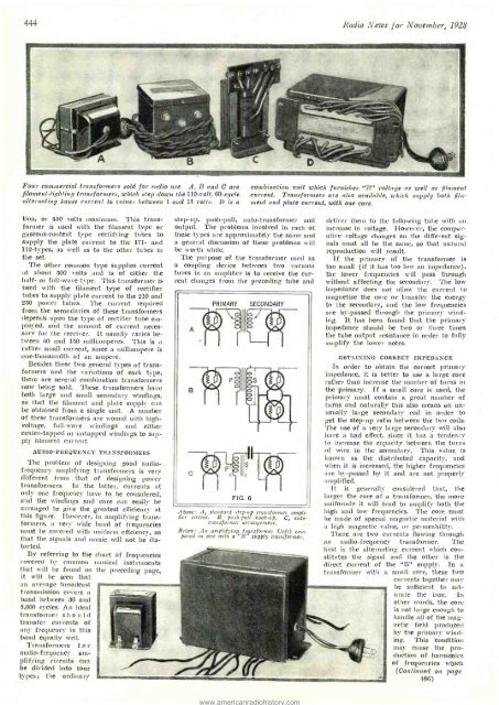
Four commercial transformers sold for radio use. A, B and C are<br />
filament -lighting transformers, which step down the 110 -volt, 60 -cycle<br />
alternating house current to values between 1 and 15 volts. D is a<br />
combination unit which furnishes "B" voltage as well as filament<br />
current. Transformers are also available, which supply both fibcment<br />
and plate current, with one core.<br />
tion, or 450 volts maximum. This transformer<br />
is used with the filament type or<br />
gaseous- content type rectifying tubes to<br />
supply the plate current to the 171- and<br />
112 -types, as well as to the other tubes in<br />
the set.<br />
The other common type supplies current<br />
at about 500 volts and is of either the<br />
half- or full -wave type. This transformer is<br />
Used with the filament type of rectifier<br />
tubes to supply plate current to the 210 and<br />
250 power tubes. The current required<br />
from the secondaries of these transformers<br />
depends upon the type of rectifier tube employed,<br />
and the amount of current necessary<br />
for the receiver. It usually varies between<br />
60 and 150 milliamperes. This is a<br />
rather small current, since a milliampere is<br />
one- thousandth of an ampere.<br />
Besicles these two general types of transformers<br />
and the variations of each type,<br />
there are several combination transformers<br />
now being sold. These transformers have<br />
both large and small secondary windings,<br />
so that the filament and plate supply can<br />
be obtained from a single unit. A number<br />
of these transformers are wound with high -<br />
voltage, full -wave windings and either<br />
center -tapped or untapped windings to supply<br />
filament current.<br />
AUDIO -FREQUENCY TRANSFORMERS<br />
The problem of designing good audio -<br />
frequency amplifying transformers is very<br />
different from that of designing power<br />
transformers. In the latter, currents at<br />
only one frequency have to be considered,<br />
and the windings and core can easily be<br />
arranged to give the greatest efficiency at<br />
this figure. However, in amplifying transformers,<br />
a very wide band of frequencies<br />
must be covered with uniform efficiency, so<br />
that the signals and music will not be distorted.<br />
By referring to the chart of frequencies<br />
covered by common musical instruments<br />
that will be found on the preceding page,<br />
it will<br />
be seen that<br />
an average broadcast<br />
transmission covers a<br />
band between 30 and<br />
5,000 cycles. An ideal<br />
transformer should<br />
transfer currents of<br />
any frequency in this<br />
band equally well.<br />
Transformers f o r<br />
audio-frequency amplifying<br />
circuits can<br />
be divided into four<br />
types; the ordinary<br />
step -up, push -pull, auto- transformer and<br />
output. The problems involved in each of<br />
these types are approximately the same and<br />
a general discussion of these problems will<br />
be worth while.<br />
The purpose of the transformer used as<br />
a coupling device between two vacuum<br />
tubes in an amplifier is to receive the current<br />
changes from the preceding tube and<br />
Above: A, standard step -up transformer amplifier<br />
circuit. B, push -pull hook-up. C, auto -.<br />
transformer arrangement.<br />
Below: An amplifying transformer (left) compared<br />
in size with a "B" supply transformer.<br />
deliver them to the following tube with an<br />
increase in voltage. However, the compa r-<br />
ative voltage changes on the different signals<br />
must all be the same, so that natural<br />
reproduction will result.<br />
If the primary of the transformer is<br />
too small (if it has too low an impedance),<br />
the lower frequencies will pass through<br />
without affecting the secondary. The low<br />
impedance does not allow the current to<br />
magnetize the core or transfer the energy<br />
to the secondary, and the low frequencies<br />
are by- passed through the primary wind-<br />
ing. It has been found that the primary<br />
impedance should be two or three times<br />
the tube output resistance in order to fully<br />
amplify the lower notes.<br />
OBTAINING CORRECT IMPEDANCE<br />
In order to obtain the correct primary<br />
impedance, it is better to use a large core<br />
rather than increase the number of turns in<br />
the primary. If a small core is used, the<br />
primary 'must contain a great number of<br />
turns and naturally this also means an unusually<br />
large secondary coil in order to<br />
get the step -up ratio between the two coils.<br />
'l'he use of a very large secondary will also<br />
have a bad effect, since it has a tendency<br />
to increase the capacity between the turns<br />
of wire in the secondary. This value is<br />
known as the distributed capacity, and<br />
when it is increased, the higher frequencies<br />
are by- passed by it and are not properly<br />
amplified.<br />
It is generally considered that, the<br />
larger the core of a transformer, the more<br />
uniformly it will tend to amplify both the<br />
high and low frequencies. The core must<br />
be made of special magnetic material with<br />
a high magnetic value, or permeability.<br />
'/'here are two currents flowing through<br />
an audio- frequency transformer. The<br />
first is the alternating current which constitutes<br />
the signal and the other -is the<br />
direct current of the "B" supply. In a<br />
transformer with a small core, these two<br />
currents together may<br />
be sufficient to saturate<br />
the iron. In<br />
other words, the core<br />
is not large enough to<br />
handle all of the magnetic<br />
field produced<br />
by the primary winding.<br />
This condition<br />
may cause the production<br />
of harmonics<br />
of frequencies which<br />
(Continued on. page<br />
486)


