

TELEVISION NUMBER - AmericanRadioHistory.Com
TELEVISION NUMBER - AmericanRadioHistory.Com
TELEVISION NUMBER - AmericanRadioHistory.Com

You also want an ePaper? Increase the reach of your titles
YUMPU automatically turns print PDFs into web optimized ePapers that Google loves.
www.americanradiohistory.com<br />
448<br />
the difference between the two frequencies<br />
present in the grid circuit. By tuning the<br />
oscillator circuit this third frequency may<br />
he wade equal to that, say 535 kilocycles<br />
(560 meters), to which the receiver proper<br />
has been tuned preciously and the signal<br />
from the broadcast station will be amplified<br />
in the receiver and heard in the loud<br />
speaker.<br />
From the foregoing explanation it is apparent<br />
that an installation, which includes<br />
a timed -R.F. receiver and the Pre -Selector,<br />
really amounts to a superheterodyne receiver;<br />
in which the Pre -Selector functions<br />
as the so- called "first detector" and oscillator,<br />
while the R.F. amplifier of the receiver<br />
proper serves as the intermediate<br />
amplifier of the combination.<br />
FEATURES OF THE CIRCUIT<br />
The tremendous selectivity afforded by<br />
the Pre- Selector is due largely to the frequency-<br />
changing process involved. In addition,<br />
the Pre- Selector combination provides<br />
better selectivity than the average<br />
superheterodyne receiver; because the R.F.<br />
amplifier of even a very broad -tuning broadcast<br />
receiver is tuned much more sharply<br />
than are the coupling transformers ordinarily<br />
employed in the intermediate stages<br />
of a regular superheterodyne receiver.<br />
Regeneration in the detector circuit of<br />
the Pre- Selector is not required for the<br />
sake of selectivity, but is used solely for<br />
r<br />
30 TURNS<br />
TAPPED 15?" TURN.<br />
#30 D.S.C. PRIMARY<br />
116= DIAMETER.<br />
-Id-<br />
N<br />
IÌI<br />
114 TURNS SPACED<br />
%28 D.S.C. SECONDARY`<br />
2 "- DIAMETER )<br />
64 TURNS *36DSC.<br />
TICKLER 11/2."-DIA. LI<br />
ri<br />
Radio News for November, 1928<br />
47 TURNS<br />
Z8 D.S.C.<br />
2 "- DIAMETER<br />
12 -TURN# 36 D.S.0<br />
PICK -UP<br />
14.-DIAMETER<br />
47 TURNS 4128 D.S.G.<br />
2 "- DIAMETER<br />
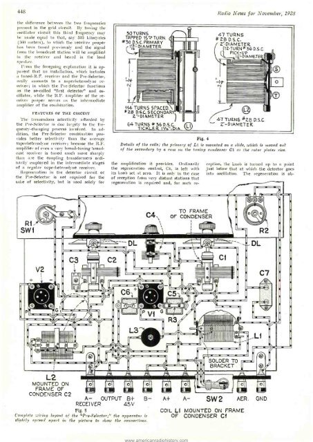
Fig. 4<br />
Details of the coils; the primary of L1 is mounted on a slide, which is moved out<br />
of the secondary by a cam on the tuning condenser Cl as the rotor plates rise.<br />
the amplification it provides. Ordinarily<br />
the regeneration control, C4, is left with<br />
its knob set at zero. It is only in the case<br />
of reception from very distant stations that<br />
regeneration is required and, for such re-<br />
ception, the knob is turned up to a point<br />
just below that at which the detector goes<br />
into oscillation. The regeneration is ob-<br />
R1-<br />
SW1<br />
IIIIIIIIIIIIIIIIIII<br />
C4,<br />
TO FRAME<br />
OF CONDENSER<br />
Illllllllllllllllr<br />
+<br />
V2<br />
J'<br />
i-<br />
IlPnnnnuq m<br />
I :,, n'lll ...<br />
. 1<br />
1<br />
=°ï'<br />
°<br />
Illla IIc : M '<br />
Imïlüüiüiüilddlau nu 1 IIII<br />
L2<br />
MOUNTED ON<br />
FRAME OF<br />
CONDENSER C2<br />
I1<br />
r<br />
si<br />
aÌÍÍÌÍIIII<br />
l<br />
I<br />
JIM PIPIT !I<br />
ailíi.!IiI<br />
ii:<br />
11<br />
1 r-<br />
!lgtIIIIII<br />
SOLDER TO<br />
BRACKET<br />
A- OUTPUT B+ B- A+ A- SW2 AER.<br />
RECEIVER<br />
45V<br />
Fig. 5<br />
<strong>Com</strong>plete wiring layout of the "Pre- Selector;" the apparatus is<br />
*lightly spread apart in the picture to show the connections.<br />
COIL LI MOUNTED ON FRAME<br />
OF CONDENSER Cl<br />
GND<br />
1


