ekS - Instytut Agrofizyki im. Bohdana DobrzaÅskiego PAN w Lublinie ...
ekS - Instytut Agrofizyki im. Bohdana DobrzaÅskiego PAN w Lublinie ...
ekS - Instytut Agrofizyki im. Bohdana DobrzaÅskiego PAN w Lublinie ...

You also want an ePaper? Increase the reach of your titles
YUMPU automatically turns print PDFs into web optimized ePapers that Google loves.
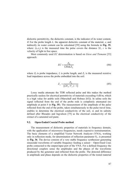
dielectric permittivity, the dielectric constant, is the indicator of its water content,<br />
θ. For the probe length L, the apparent dielectric constant of the material, ε, and<br />
indirectly its water content can be calculated [59] using the formula in Fig. 35,<br />
where: (t b -t a ) is the measured t<strong>im</strong>e the pulse covers the distance 2L, c is the<br />
velocity of light in free space.<br />
Most commonly used EC determination is based on Giese and Tiemann [33]<br />
approach:<br />
Z0<br />
EC = (84)<br />
120πLZ L<br />
where Z 0 is probe <strong>im</strong>pedance, L is probe length, and Z L is the measured resistive<br />
load <strong>im</strong>pedance across the probe embedded into the soil:<br />
Z0<br />
Z L =<br />
(85)<br />
[( 2V<br />
0 / V f ) −1]<br />
Lossy media attenuate the TDR reflected pulse and this makes the method<br />
practically useless for electrical permittivity of materials exceeding 4 dS/m, which<br />
is a high value for arable soils (Marschall and Holmes [63]). In saline soils the<br />
signal reflected from the end of the probe rods is completely attenuated (no<br />
amplitude at point b in Fig. 35). The measurement of the amplitude of the pulse<br />
reflected from the end of the probe, taken s<strong>im</strong>ultaneously to the pulse travel t<strong>im</strong>e,<br />
enables to determine the electrical conductivity of the soil, σ, and its salinity<br />
defined after Rhoades and Ingvalson [75] as the electrical conductivity of the<br />
extract of a saturated soil paste.<br />
9.2. Open-Ended Coaxial Probe method<br />
The measurement of dielectric properties of materials in frequency domain,<br />
with the application of microwave frequencies, needs expensive instrumentation.<br />
The basic elements of a s<strong>im</strong>plified Vector Network Analyzer (VNA), working<br />
only in reflection mode, for determination of reflection parameter S 11 is presented<br />
in Fig. 36. The device consists of a very stable frequency synthesizer generating<br />
sinusoidal waveforms of variable frequency feeding a sensor – Open-Ened Coax<br />
probe connected to the output/input port of the VNA. For a defined frequency the<br />
directional couplers sense the amplitudes and the phases of the waveforms<br />
produced by the generator and reflected from the probe. The detected difference<br />
in amplitude and phase depends on the dielectric properties of the tested material<br />
87