

Glacier Transportable Sampler - Isco
Glacier Transportable Sampler - Isco
Glacier Transportable Sampler - Isco

You also want an ePaper? Increase the reach of your titles
YUMPU automatically turns print PDFs into web optimized ePapers that Google loves.
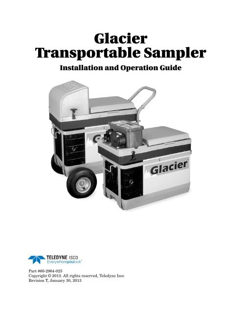
<strong>Glacier</strong><br />
<strong>Transportable</strong> <strong>Sampler</strong><br />
Installation and Operation Guide<br />
Part #60-2964-025<br />
Copyright © 2013. All rights reserved, Teledyne <strong>Isco</strong><br />
Revision T, January 30, 2013
Foreword<br />
This instruction manual is designed to help you gain a thorough understanding of the<br />
operation of the equipment. Teledyne <strong>Isco</strong> recommends that you read this manual<br />
completely before placing the equipment in service.<br />
Although Teledyne <strong>Isco</strong> designs reliability into all equipment, there is always the possibility<br />
of a malfunction. This manual may help in diagnosing and repairing the malfunction.<br />
If the problem persists, call or e-mail the Teledyne <strong>Isco</strong> Technical Service Department<br />
for assistance. Simple difficulties can often be diagnosed over the phone.<br />
If it is necessary to return the equipment to the factory for service, please follow the<br />
shipping instructions provided by the Customer Service Department, including the<br />
use of the Return Authorization Number specified. Be sure to include a note<br />
describing the malfunction. This will aid in the prompt repair and return of the<br />
equipment.<br />
Teledyne <strong>Isco</strong> welcomes suggestions that would improve the information presented in<br />
this manual or enhance the operation of the equipment itself.<br />
Teledyne <strong>Isco</strong> is continually improving its products and reserves the right to<br />
change product specifications, replacement parts, schematics, and instructions<br />
without notice.<br />
Contact Information<br />
Customer Service<br />
Phone: (800) 228-4373 (USA, Canada, Mexico)<br />
(402) 464-0231 (Outside North America)<br />
Fax: (402) 465-3022<br />
Email:<br />
<strong>Isco</strong>CSR@teledyne.com<br />
Technical Support<br />
Phone: Toll Free (866) 298-6174 (<strong>Sampler</strong>s and Flow Meters)<br />
Toll Free (800) 775-2965<br />
(Syringe Pumps and Liquid Chromatography)<br />
Email:<br />
<strong>Isco</strong>Service@teledyne.com<br />
Return equipment to: 4700 Superior Street, Lincoln, NE 68504-1398<br />
Other Correspondence<br />
Mail to: P.O. Box 82531, Lincoln, NE 68501-2531<br />
Email:<br />
<strong>Isco</strong>Info@teledyne.com<br />
Revised September 2012
<strong>Glacier</strong> <strong>Transportable</strong> <strong>Sampler</strong><br />
Safety<br />
<strong>Glacier</strong> <strong>Transportable</strong> <strong>Sampler</strong><br />
<strong>Glacier</strong> Safety Information<br />
Electrical Requirements<br />
The <strong>Isco</strong> <strong>Glacier</strong> <strong>Transportable</strong> <strong>Sampler</strong> is a “definite purpose”<br />
device, intended for use only with compatible <strong>Isco</strong> equipment. Do<br />
not use this product with any other manufacturers’ equipment,<br />
or for any other purpose. Use for any purpose not described in<br />
this manual could cause personal injury or property damage.<br />
The <strong>Glacier</strong> requires 12 VDC at 6 amperes. The DC power input<br />
is through the two-pin connector on the side of the refrigerated<br />
compartment. The <strong>Isco</strong>-supplied DC connect cables provide<br />
over-current protection through the use of an in-line 8A, 32V<br />
fuse. The dual-power configuration of the <strong>Glacier</strong> may also be<br />
powered by an 87 to 264 VAC, 47 to 63 Hz, 2 ampere power<br />
source using the attached AC line cord. The AC-powered <strong>Glacier</strong><br />
is protected by an internal thermal cut-out. Additionally, the controller<br />
circuitry is protected by an internal 3.75 ampere PTC<br />
(Positive Temperature Coefficient) device.<br />
WARNING<br />
Electrocution hazard. Never manipulate electrical switches<br />
or power connections with wet hands or when your feet are<br />
in contact with water.<br />
WARNING<br />
Dual-power units only:<br />
AC electrical power must meet the applicable electrical<br />
code requirements for your installation and must be<br />
provided with an earth ground connection. If necessary,<br />
consult with a certified electrician to ensure that AC power<br />
is provided in accordance with the local electrical code.<br />
AC Powered <strong>Glacier</strong>s<br />
The AC power cord of this device is quipped with a three-prong<br />
grounding plug designed to mate with a grounded power outlet.<br />
Grounding minimizes the possibility of electrical shock.<br />
It is the user’s responsibility to ensure that the AC power source<br />
is properly grounded. If in doubt, have the outlet checked by a<br />
qualified electrician.<br />
If the available AC power outlet only accepts two prongs, or if it<br />
is determined that the outlet is improperly grounded, the outlet<br />
must be replaced by a qualified electrician before attempting to<br />
power this device.<br />
WARNING<br />
Never modify the AC power cord or use a three-prong to<br />
two-prong adapter.<br />
WARNING<br />
If this device’s power cord is frayed or otherwise damaged,<br />
discontinue its use immediately. The AC power cord is not<br />
user-serviceable and must be returned to the factory for<br />
repair or replacement.<br />
iii
<strong>Glacier</strong> <strong>Transportable</strong> <strong>Sampler</strong><br />
Safety<br />
General Warnings<br />
Before installing, operating, or maintaining this equipment, it is<br />
imperative that all hazards and preventive measures are fully<br />
understood. While specific hazards may vary according to location<br />
and application, take heed in the following general warnings:<br />
WARNING<br />
Avoid hazardous practices! If you use this instrument in<br />
any way not specified in this manual, the protection<br />
provided by the instrument may be impaired.<br />
Hazard Severity Levels<br />
This manual applies Hazard Severity Levels to the safety alerts,<br />
These three levels are described in the sample alerts below.<br />
CAUTION<br />
Cautions identify a potential hazard, which if not avoided, may<br />
result in minor or moderate injury. This category can also warn<br />
you of unsafe practices, or conditions that may cause property<br />
damage.<br />
WARNING<br />
Warnings identify a potentially hazardous condition, which<br />
if not avoided, could result in death or serious injury.<br />
DANGER<br />
DANGER – limited to the most extreme situations<br />
to identify an imminent hazard, which if not<br />
avoided, will result in death or serious injury.<br />
iv
<strong>Glacier</strong> <strong>Transportable</strong> <strong>Sampler</strong><br />
Safety<br />
Hazard Symbols<br />
Warnings and Cautions<br />
The equipment and this manual use symbols to warn of hazards.<br />
The symbols are explained below.<br />
Hazard Symbols<br />
The exclamation point within the triangle is a warning sign alerting you of<br />
important instructions in the instrument’s technical reference manual.<br />
The lightning flash and arrowhead within the triangle is a warning sign alerting<br />
you of “dangerous voltage” inside the product.<br />
This symbol warns you that your fingers or hands will sustain serious injury<br />
if you place them between the moving parts of the mechanism near this<br />
symbol.<br />
Symboles de sécurité<br />
Ce symbole signale l’existence d’instructions importantes relatives au<br />
produit dans ce manuel.<br />
Ce symbole signale la présence d’un danger d’électocution.<br />
Warnungen und Vorsichtshinweise<br />
Ce symbole vous avertit que les mains ou les doigts seront blessès sérieusement<br />
si vous les mettez entre les éléments en mouvement du<br />
mécanisme près de ce symbole.<br />
Das Ausrufezeichen in Dreieck ist ein Warnzeichen, das Sie darauf<br />
aufmerksam macht, daß wichtige Anleitungen zu diesem Handbuch<br />
gehören.<br />
Advertencias y Precauciones<br />
Der gepfeilte Blitz im Dreieck ist ein Warnzeichen, das Sei vor “gefährlichen<br />
Spannungen” im Inneren des Produkts warnt.<br />
Esta señal le advierte sobre la importancia de las instrucciones del manual<br />
que acompañan a este producto.<br />
Esta señal alerta sobre la presencia de alto voltaje en el interior del<br />
producto.<br />
v
<strong>Glacier</strong> <strong>Transportable</strong> <strong>Sampler</strong><br />
Safety<br />
vi
<strong>Glacier</strong> <strong>Transportable</strong> <strong>Sampler</strong><br />
Table of Contents<br />
Section 1 Introduction<br />
1.1 Overview . . . . . . . . . . . . . . . . . . . . . . . . . . . . . . . . . . . . . . . . . . . . . . . . . . . . . . . . . . 1-1<br />
1.1.1 Typical Applications . . . . . . . . . . . . . . . . . . . . . . . . . . . . . . . . . . . . . . . . . . . 1-2<br />
1.1.2 Compatible Equipment . . . . . . . . . . . . . . . . . . . . . . . . . . . . . . . . . . . . . . . . . 1-2<br />
1.2 <strong>Glacier</strong> Features . . . . . . . . . . . . . . . . . . . . . . . . . . . . . . . . . . . . . . . . . . . . . . . . . . . . 1-3<br />
1.3 Technical Specifications . . . . . . . . . . . . . . . . . . . . . . . . . . . . . . . . . . . . . . . . . . . . . . 1-5<br />
Section 2 Installation<br />
2.1 Installation Checklist . . . . . . . . . . . . . . . . . . . . . . . . . . . . . . . . . . . . . . . . . . . . . . . . 2-1<br />
2.2 Positioning the <strong>Sampler</strong> . . . . . . . . . . . . . . . . . . . . . . . . . . . . . . . . . . . . . . . . . . . . . . 2-1<br />
2.3 Replacing the Pump Tube. . . . . . . . . . . . . . . . . . . . . . . . . . . . . . . . . . . . . . . . . . . . . 2-3<br />
2.3.1 Pump Tube Warning . . . . . . . . . . . . . . . . . . . . . . . . . . . . . . . . . . . . . . . . . . . 2-3<br />
2.3.2 Visual Inspection . . . . . . . . . . . . . . . . . . . . . . . . . . . . . . . . . . . . . . . . . . . . . . 2-4<br />
2.4 Install the Bottle . . . . . . . . . . . . . . . . . . . . . . . . . . . . . . . . . . . . . . . . . . . . . . . . . . . . 2-5<br />
2.5 Insert the Temperature Sensor into the Bottle . . . . . . . . . . . . . . . . . . . . . . . . . . . . 2-6<br />
2.6 Route the Discharge Tube. . . . . . . . . . . . . . . . . . . . . . . . . . . . . . . . . . . . . . . . . . . . . 2-7<br />
2.7 Connect a Power Source . . . . . . . . . . . . . . . . . . . . . . . . . . . . . . . . . . . . . . . . . . . . . . 2-8<br />
2.7.1 12 VDC Power Sources . . . . . . . . . . . . . . . . . . . . . . . . . . . . . . . . . . . . . . . . . 2-8<br />
2.7.2 Battery Recommendations . . . . . . . . . . . . . . . . . . . . . . . . . . . . . . . . . . . . . . 2-9<br />
2.8 Connect a Suction Line and Strainer. . . . . . . . . . . . . . . . . . . . . . . . . . . . . . . . . . . . 2-9<br />
2.8.1 Cutting the Suction Line . . . . . . . . . . . . . . . . . . . . . . . . . . . . . . . . . . . . . . . 2-11<br />
2.8.2 Connecting Vinyl Suction Line . . . . . . . . . . . . . . . . . . . . . . . . . . . . . . . . . . 2-11<br />
2.8.3 Connecting PTFE Suction Line . . . . . . . . . . . . . . . . . . . . . . . . . . . . . . . . . . 2-12<br />
2.8.4 Strainers . . . . . . . . . . . . . . . . . . . . . . . . . . . . . . . . . . . . . . . . . . . . . . . . . . . . 2-12<br />
2.8.5 Intake Placement . . . . . . . . . . . . . . . . . . . . . . . . . . . . . . . . . . . . . . . . . . . . . 2-13<br />
2.8.6 Pressurized lines . . . . . . . . . . . . . . . . . . . . . . . . . . . . . . . . . . . . . . . . . . . . . 2-14<br />
2.9 External Connections . . . . . . . . . . . . . . . . . . . . . . . . . . . . . . . . . . . . . . . . . . . . . . . 2-14<br />
2.10 Calibrate the Sample Volumes. . . . . . . . . . . . . . . . . . . . . . . . . . . . . . . . . . . . . . . 2-15<br />
2.10.1 Calibration Step 1 . . . . . . . . . . . . . . . . . . . . . . . . . . . . . . . . . . . . . . . . . . . 2-15<br />
2.10.2 Calibration Step 2 . . . . . . . . . . . . . . . . . . . . . . . . . . . . . . . . . . . . . . . . . . . 2-16<br />
2.10.3 Calibration Step 3 . . . . . . . . . . . . . . . . . . . . . . . . . . . . . . . . . . . . . . . . . . . 2-16<br />
2.10.4 Calibration Step 4 . . . . . . . . . . . . . . . . . . . . . . . . . . . . . . . . . . . . . . . . . . . 2-17<br />
2.10.5 Calibration Step 5 . . . . . . . . . . . . . . . . . . . . . . . . . . . . . . . . . . . . . . . . . . . 2-17<br />
2.10.6 Calibration Step 6 . . . . . . . . . . . . . . . . . . . . . . . . . . . . . . . . . . . . . . . . . . . 2-18<br />
2.11 Start the Program . . . . . . . . . . . . . . . . . . . . . . . . . . . . . . . . . . . . . . . . . . . . . . . . . 2-18<br />
2.12 Secure the <strong>Glacier</strong> . . . . . . . . . . . . . . . . . . . . . . . . . . . . . . . . . . . . . . . . . . . . . . . . . 2-19<br />
Section 3 Programming<br />
3.1 Programming Overview . . . . . . . . . . . . . . . . . . . . . . . . . . . . . . . . . . . . . . . . . . . . . . 3-1<br />
3.2 The <strong>Glacier</strong> Interface . . . . . . . . . . . . . . . . . . . . . . . . . . . . . . . . . . . . . . . . . . . . . . . . 3-1<br />
3.2.1 The <strong>Glacier</strong> Display . . . . . . . . . . . . . . . . . . . . . . . . . . . . . . . . . . . . . . . . . . . . 3-1<br />
3.2.2 The <strong>Glacier</strong> Keypad . . . . . . . . . . . . . . . . . . . . . . . . . . . . . . . . . . . . . . . . . . . . 3-1<br />
3.3 <strong>Glacier</strong> Operating States . . . . . . . . . . . . . . . . . . . . . . . . . . . . . . . . . . . . . . . . . . . . . 3-1<br />
3.3.1 Interactive States . . . . . . . . . . . . . . . . . . . . . . . . . . . . . . . . . . . . . . . . . . . . . 3-1<br />
3.3.2 Non-interactive States . . . . . . . . . . . . . . . . . . . . . . . . . . . . . . . . . . . . . . . . . . 3-2<br />
3.4 Programming the <strong>Glacier</strong> . . . . . . . . . . . . . . . . . . . . . . . . . . . . . . . . . . . . . . . . . . . . . 3-2<br />
vii
<strong>Glacier</strong> <strong>Transportable</strong> <strong>Sampler</strong><br />
Table of Contents<br />
3.5 One-button Programming. . . . . . . . . . . . . . . . . . . . . . . . . . . . . . . . . . . . . . . . . . . . . 3-2<br />
3.5.1 Stored Program . . . . . . . . . . . . . . . . . . . . . . . . . . . . . . . . . . . . . . . . . . . . . . . 3-2<br />
3.6 Standard Programming . . . . . . . . . . . . . . . . . . . . . . . . . . . . . . . . . . . . . . . . . . . . . . 3-3<br />
3.6.1 Programming Step 1 – Pacing . . . . . . . . . . . . . . . . . . . . . . . . . . . . . . . . . . . . 3-3<br />
3.6.2 Programming Step 2 – Pacing Interval . . . . . . . . . . . . . . . . . . . . . . . . . . . . 3-4<br />
3.6.3 Programming Step 3 – Bottle Volume . . . . . . . . . . . . . . . . . . . . . . . . . . . . . 3-4<br />
3.6.4 Programming Step 4 – Number of Samples . . . . . . . . . . . . . . . . . . . . . . . . . 3-5<br />
3.6.5 Programming Step 5 – Sample Volume . . . . . . . . . . . . . . . . . . . . . . . . . . . . 3-6<br />
3.6.6 Programming Step 6 – Program Start Time . . . . . . . . . . . . . . . . . . . . . . . . 3-6<br />
3.6.7 Programming Step 7 – Suction Line . . . . . . . . . . . . . . . . . . . . . . . . . . . . . . . 3-7<br />
3.7 Setting the Time and Date . . . . . . . . . . . . . . . . . . . . . . . . . . . . . . . . . . . . . . . . . . . . 3-8<br />
3.8 <strong>Glacier</strong> Options . . . . . . . . . . . . . . . . . . . . . . . . . . . . . . . . . . . . . . . . . . . . . . . . . . . . . 3-8<br />
3.8.1 Program Lock . . . . . . . . . . . . . . . . . . . . . . . . . . . . . . . . . . . . . . . . . . . . . . . . . 3-9<br />
3.8.2 Storing a Program . . . . . . . . . . . . . . . . . . . . . . . . . . . . . . . . . . . . . . . . . . . . 3-10<br />
3.8.3 Disable Bottle Full Detection . . . . . . . . . . . . . . . . . . . . . . . . . . . . . . . . . . . 3-10<br />
3.8.4 Liquid Detector Disable . . . . . . . . . . . . . . . . . . . . . . . . . . . . . . . . . . . . . . . . 3-10<br />
3.9 Foreign Language Displays . . . . . . . . . . . . . . . . . . . . . . . . . . . . . . . . . . . . . . . . . . 3-11<br />
Section 4 Operating the <strong>Sampler</strong><br />
4.1 Overview . . . . . . . . . . . . . . . . . . . . . . . . . . . . . . . . . . . . . . . . . . . . . . . . . . . . . . . . . . 4-1<br />
4.2 Starting a Program . . . . . . . . . . . . . . . . . . . . . . . . . . . . . . . . . . . . . . . . . . . . . . . . . . 4-1<br />
4.3 Counting Down Delay Times . . . . . . . . . . . . . . . . . . . . . . . . . . . . . . . . . . . . . . . . . . 4-1<br />
4.4 <strong>Sampler</strong> Inhibit . . . . . . . . . . . . . . . . . . . . . . . . . . . . . . . . . . . . . . . . . . . . . . . . . . . . . 4-2<br />
4.5 Run State Displays . . . . . . . . . . . . . . . . . . . . . . . . . . . . . . . . . . . . . . . . . . . . . . . . . . 4-2<br />
4.5.1 Collecting a sample – . . . . . . . . . . . . . . . . . . . . . . . . . . . . . . . . . . . . . . . . . . . 4-2<br />
4.5.2 Waiting to sample – . . . . . . . . . . . . . . . . . . . . . . . . . . . . . . . . . . . . . . . . . . . . 4-2<br />
4.5.3 Errors – . . . . . . . . . . . . . . . . . . . . . . . . . . . . . . . . . . . . . . . . . . . . . . . . . . . . . 4-3<br />
4.6 Sample Collection Cycle . . . . . . . . . . . . . . . . . . . . . . . . . . . . . . . . . . . . . . . . . . . . . . 4-3<br />
4.6.1 Pre-purge . . . . . . . . . . . . . . . . . . . . . . . . . . . . . . . . . . . . . . . . . . . . . . . . . . . . 4-3<br />
4.6.2 Fill . . . . . . . . . . . . . . . . . . . . . . . . . . . . . . . . . . . . . . . . . . . . . . . . . . . . . . . . . . 4-3<br />
4.6.3 Post-purge . . . . . . . . . . . . . . . . . . . . . . . . . . . . . . . . . . . . . . . . . . . . . . . . . . . 4-3<br />
4.7 Refrigeration Control . . . . . . . . . . . . . . . . . . . . . . . . . . . . . . . . . . . . . . . . . . . . . . . . 4-4<br />
4.8 Pausing or Stopping a Program . . . . . . . . . . . . . . . . . . . . . . . . . . . . . . . . . . . . . . . . 4-4<br />
4.9 Program Completion . . . . . . . . . . . . . . . . . . . . . . . . . . . . . . . . . . . . . . . . . . . . . . . . . 4-4<br />
4.10 Post-sampling Activities . . . . . . . . . . . . . . . . . . . . . . . . . . . . . . . . . . . . . . . . . . . . . 4-4<br />
4.10.1 Recovering the <strong>Sampler</strong> . . . . . . . . . . . . . . . . . . . . . . . . . . . . . . . . . . . . . . . . 4-5<br />
4.10.2 Preparing the Full Sample Bottle . . . . . . . . . . . . . . . . . . . . . . . . . . . . . . . . 4-5<br />
4.11 Log . . . . . . . . . . . . . . . . . . . . . . . . . . . . . . . . . . . . . . . . . . . . . . . . . . . . . . . . . . . . . . 4-5<br />
4.11.1 Errors . . . . . . . . . . . . . . . . . . . . . . . . . . . . . . . . . . . . . . . . . . . . . . . . . . . . . . 4-6<br />
4.11.2 Viewing Log Reports using <strong>Isco</strong> SAMPLINK software . . . . . . . . . . . . . . . 4-7<br />
4.11.3 Viewing Log Reports using a Terminal Program . . . . . . . . . . . . . . . . . . . . 4-7<br />
4.12 Grab Samples . . . . . . . . . . . . . . . . . . . . . . . . . . . . . . . . . . . . . . . . . . . . . . . . . . . . . 4-8<br />
Section 5 Maintenance<br />
5.1 Overview . . . . . . . . . . . . . . . . . . . . . . . . . . . . . . . . . . . . . . . . . . . . . . . . . . . . . . . . . . 5-1<br />
5.2 Cleaning. . . . . . . . . . . . . . . . . . . . . . . . . . . . . . . . . . . . . . . . . . . . . . . . . . . . . . . . . . . 5-1<br />
5.2.1 Cleaning the <strong>Glacier</strong> Exterior . . . . . . . . . . . . . . . . . . . . . . . . . . . . . . . . . . . . 5-1<br />
5.2.2 Cleaning the Bottles . . . . . . . . . . . . . . . . . . . . . . . . . . . . . . . . . . . . . . . . . . . 5-2<br />
5.2.3 Cleaning the Suction Line and Tubing . . . . . . . . . . . . . . . . . . . . . . . . . . . . . 5-2<br />
5.2.4 Cleaning the Temperature Sensor . . . . . . . . . . . . . . . . . . . . . . . . . . . . . . . . 5-2<br />
5.2.5 Cleaning Protocols for Priority Pollutants . . . . . . . . . . . . . . . . . . . . . . . . . . 5-2<br />
5.3 Defrosting the <strong>Glacier</strong> Refrigerated Compartment. . . . . . . . . . . . . . . . . . . . . . . . . 5-3<br />
5.4 Replacing the Pump Tube. . . . . . . . . . . . . . . . . . . . . . . . . . . . . . . . . . . . . . . . . . . . . 5-4<br />
5.4.1 Removing the Tube . . . . . . . . . . . . . . . . . . . . . . . . . . . . . . . . . . . . . . . . . . . . 5-4<br />
5.4.2 Replacing the Tube . . . . . . . . . . . . . . . . . . . . . . . . . . . . . . . . . . . . . . . . . . . . 5-6<br />
5.4.3 Resetting the Pump Tube Warning . . . . . . . . . . . . . . . . . . . . . . . . . . . . . . . 5-6<br />
viii
<strong>Glacier</strong> <strong>Transportable</strong> <strong>Sampler</strong><br />
Table of Contents<br />
5.4.4 Optimizing Pump Performance . . . . . . . . . . . . . . . . . . . . . . . . . . . . . . . . . . . 5-6<br />
5.5 Replacing the Discharge Tube . . . . . . . . . . . . . . . . . . . . . . . . . . . . . . . . . . . . . . . . . 5-6<br />
5.6 Servicing Batteries . . . . . . . . . . . . . . . . . . . . . . . . . . . . . . . . . . . . . . . . . . . . . . . . . . 5-7<br />
5.7 Replacing the Internal Desiccant . . . . . . . . . . . . . . . . . . . . . . . . . . . . . . . . . . . . . . . 5-8<br />
5.7.1 Renewing the Desiccant . . . . . . . . . . . . . . . . . . . . . . . . . . . . . . . . . . . . . . . . 5-9<br />
5.8 <strong>Glacier</strong> Self-diagnostics. . . . . . . . . . . . . . . . . . . . . . . . . . . . . . . . . . . . . . . . . . . . . . 5-10<br />
5.9 Contacting Teledyne <strong>Isco</strong> for Assistance . . . . . . . . . . . . . . . . . . . . . . . . . . . . . . . . 5-12<br />
5.9.1 Return Instructions . . . . . . . . . . . . . . . . . . . . . . . . . . . . . . . . . . . . . . . . . . . 5-12<br />
5.10 Replacement Parts . . . . . . . . . . . . . . . . . . . . . . . . . . . . . . . . . . . . . . . . . . . . . . . . 5-13<br />
5.11 Software Updates . . . . . . . . . . . . . . . . . . . . . . . . . . . . . . . . . . . . . . . . . . . . . . . . . 5-13<br />
Appendix A Replacement Parts<br />
A.1 Overview . . . . . . . . . . . . . . . . . . . . . . . . . . . . . . . . . . . . . . . . . . . . . . . . . . . . . . . . . . A-1<br />
Appendix B Accessories<br />
B.1 Accessories List. . . . . . . . . . . . . . . . . . . . . . . . . . . . . . . . . . . . . . . . . . . . . . . . . . . . . B-1<br />
B.1.1 Bottle Kits . . . . . . . . . . . . . . . . . . . . . . . . . . . . . . . . . . . . . . . . . . . . . . . . . . . B-1<br />
B.1.2 Replacement Bottles . . . . . . . . . . . . . . . . . . . . . . . . . . . . . . . . . . . . . . . . . . . B-1<br />
B.1.3 General Accessories . . . . . . . . . . . . . . . . . . . . . . . . . . . . . . . . . . . . . . . . . . . . B-1<br />
B.1.4 Suction line and strainers . . . . . . . . . . . . . . . . . . . . . . . . . . . . . . . . . . . . . . . B-2<br />
B.1.5 DC Power Connect Cables . . . . . . . . . . . . . . . . . . . . . . . . . . . . . . . . . . . . . . B-2<br />
B.1.6 Connect Cables and Interfaces . . . . . . . . . . . . . . . . . . . . . . . . . . . . . . . . . . . B-3<br />
Appendix C Material Safety Data Sheets<br />
C.1 Overview . . . . . . . . . . . . . . . . . . . . . . . . . . . . . . . . . . . . . . . . . . . . . . . . . . . . . . . . . . C-1<br />
Appendix D Battery Selection Guide<br />
D.1 Introduction . . . . . . . . . . . . . . . . . . . . . . . . . . . . . . . . . . . . . . . . . . . . . . . . . . . . . . . D-1<br />
D.2 Determining the Power Consumption. . . . . . . . . . . . . . . . . . . . . . . . . . . . . . . . . . . D-1<br />
List of Figures<br />
1-1 <strong>Glacier</strong> <strong>Transportable</strong> <strong>Sampler</strong>s . . . . . . . . . . . . . . . . . . . . . . . . . . . . . . . . . . . . . . . 1-1<br />
1-2 <strong>Glacier</strong> Features . . . . . . . . . . . . . . . . . . . . . . . . . . . . . . . . . . . . . . . . . . . . . . . . . . . . 1-3<br />
1-3 <strong>Glacier</strong> Keypad Buttons . . . . . . . . . . . . . . . . . . . . . . . . . . . . . . . . . . . . . . . . . . . . . . 1-4<br />
2-1 Pump Housing Cover Removed . . . . . . . . . . . . . . . . . . . . . . . . . . . . . . . . . . . . . . . . 2-4<br />
2-2 Placement of Bottle and Retainer (top view) . . . . . . . . . . . . . . . . . . . . . . . . . . . . . 2-6<br />
2-3 Temperature Sensor in Bottle . . . . . . . . . . . . . . . . . . . . . . . . . . . . . . . . . . . . . . . . . 2-7<br />
2-4 Discharge Tube and Tube Guide . . . . . . . . . . . . . . . . . . . . . . . . . . . . . . . . . . . . . . . 2-7<br />
2-5 Attaching the suction line to the pump tubing . . . . . . . . . . . . . . . . . . . . . . . . . . . 2-11<br />
2-6 Standard Weighted Polypropylene Strainer . . . . . . . . . . . . . . . . . . . . . . . . . . . . . 2-13<br />
2-7 Stainless Steel Strainer . . . . . . . . . . . . . . . . . . . . . . . . . . . . . . . . . . . . . . . . . . . . . 2-13<br />
2-8 CPVC Weighted Strainer . . . . . . . . . . . . . . . . . . . . . . . . . . . . . . . . . . . . . . . . . . . . 2-13<br />
2-9 Measuring Suction Head Height . . . . . . . . . . . . . . . . . . . . . . . . . . . . . . . . . . . . . . 2-16<br />
5-1 Liquid detector cover removed . . . . . . . . . . . . . . . . . . . . . . . . . . . . . . . . . . . . . . . . . 5-5<br />
5-2 Pump housing cover removed . . . . . . . . . . . . . . . . . . . . . . . . . . . . . . . . . . . . . . . . . 5-5<br />
5-3 Discharge Tube and Tube Guide . . . . . . . . . . . . . . . . . . . . . . . . . . . . . . . . . . . . . . . 5-7<br />
5-4 Internal Desiccant . . . . . . . . . . . . . . . . . . . . . . . . . . . . . . . . . . . . . . . . . . . . . . . . . . 5-9<br />
D-1 Amp-hours required to cool 6 liters of sample liquid from 20° C (A c ) . . . . . . . . . . D-3<br />
D-2 Amp-hours per day required to maintain sample liquid at 3° C (A m ) . . . . . . . . . D-3<br />
ix
<strong>Glacier</strong> <strong>Transportable</strong> <strong>Sampler</strong><br />
Table of Contents<br />
List of Tables<br />
1-1 <strong>Glacier</strong> <strong>Transportable</strong> <strong>Sampler</strong> Specifications . . . . . . . . . . . . . . . . . . . . . . . . . . . . 1-5<br />
2-1 Standard Bottles for the <strong>Glacier</strong> <strong>Transportable</strong> <strong>Sampler</strong> . . . . . . . . . . . . . . . . . . . 2-5<br />
2-2 Strainer/Suction Line Depths . . . . . . . . . . . . . . . . . . . . . . . . . . . . . . . . . . . . . . . . 2-12<br />
x
<strong>Glacier</strong> <strong>Transportable</strong> <strong>Sampler</strong><br />
Section 1 Introduction<br />
1.1 Overview The <strong>Glacier</strong> is a transportable refrigerated sampler, designed for<br />
automated sample collection in remote field situations where<br />
conventional, electrically-powered refrigerated samplers cannot<br />
be used. Normally, where there is no electrical power available,<br />
portable samplers using ice as the means for cooling the sample<br />
had to be used. The <strong>Glacier</strong>’s CFC-free cooling system meets the<br />
recommended EPA requirements for sample protection, eliminating<br />
the need for ice. Samples collected by the <strong>Glacier</strong> will be<br />
held at 3° C, even in extreme climates. However, some precautions<br />
and care must be taken when positioning and locating the<br />
<strong>Glacier</strong>. See section 2.2 before installation.<br />
The <strong>Glacier</strong> is ideally suited for the collection of composite<br />
samples for satisfying NPDES permit requirements. It is equally<br />
well suited for use in waste water treatment plants where portability<br />
or a compact size is needed. Since it can be operated from a<br />
12 volt battery or an internal AC converter, it can be easily<br />
moved from one location to another in the plant without worrying<br />
whether or not AC power is available.<br />
Figure 1-1 <strong>Glacier</strong> <strong>Transportable</strong> <strong>Sampler</strong>s<br />
1-1
<strong>Glacier</strong> <strong>Transportable</strong> <strong>Sampler</strong><br />
Section 1 Introduction<br />
The <strong>Glacier</strong> collects liquid samples and places them in a composite<br />
sample container. The largest standard sample container<br />
will hold 5 gallons (19 liters). A dependable peristaltic pump<br />
delivers the liquid to the bottle. Its pump, coupled with the<br />
non-contacting liquid detector, gives you accurate, repeatable<br />
sample volumes time after time. The liquid detector may also be<br />
used to halt the sampling routine when a full bottle is detected.<br />
At the heart of the sampler is the controller. It is environmentally<br />
sealed (rated NEMA 4X, 6 and IP67) to provide protection<br />
from accidental submersion and long term exposure to high<br />
humidity and corrosive gases. Its tactile keypad and 2 line by 20<br />
character display simplifies operation. In just seconds, the<br />
one-button programming procedure will load the stored program<br />
settings and run the sampling routine.<br />
1.1.1 Typical Applications The <strong>Glacier</strong> is part of Teledyne <strong>Isco</strong>’s many automated sampling<br />
solutions which include the Model 3700 and 6700 Series samplers.<br />
This versatile product line meets the demands of:<br />
• NPDES permit compliance<br />
• Pre-treatment compliance<br />
• Stormwater run-off<br />
• Combined sewer overflow<br />
• Sanitary sewer evaluations<br />
• Non-point source sampling<br />
• Biomonitoring<br />
1.1.2 Compatible<br />
Equipment<br />
Compatible <strong>Isco</strong> devices include:<br />
<strong>Isco</strong> flow measuring instruments:<br />
• 4100 Series Flow Loggers<br />
• 4200 Series Flow Meters<br />
Non-<strong>Isco</strong> device interfaces:<br />
• 4-20 mA Input Interface<br />
• Pulse Duration Input Interface<br />
<strong>Isco</strong> parameter measuring devices:<br />
• Liquid Level Actuator<br />
1-2
<strong>Glacier</strong> <strong>Transportable</strong> <strong>Sampler</strong><br />
Section 1 Introduction<br />
1.2 <strong>Glacier</strong> Features<br />
Top View<br />
2 3 4 5 6<br />
1<br />
Front View<br />
14<br />
7<br />
8 9<br />
10<br />
Side View<br />
13<br />
11 12<br />
1 <strong>Sampler</strong> Controller<br />
2 Flow meter connector<br />
3 Bulkhead fitting<br />
4 Discharge Tube<br />
5 Sample Bottle<br />
6 Sample Bottle Retainer<br />
7 Pump Tube<br />
8 Liquid Detector<br />
9 Pump Housing<br />
10 Carrying handle<br />
11 DC Power connector<br />
12 Power mode switch. Always LOW.<br />
13 AC Power Cable (Dual-power Models only)<br />
14 Refrigerated Compartment<br />
Figure 1-2 <strong>Glacier</strong> Features<br />
1-3
<strong>Glacier</strong> <strong>Transportable</strong> <strong>Sampler</strong><br />
Section 1 Introduction<br />
1<br />
5<br />
2<br />
3<br />
4<br />
1 Liquid Crystal Display (LCD) 2 rows by 20 characters<br />
2 Standby Button. When in the Off state the Standby button turns the <strong>Glacier</strong> on and places it in the<br />
Standby state. In any other state, the Standby button will place the sampler in the Off state.<br />
3 KeyPad<br />
NUMBER Buttons allow you to enter numerical values when prompted by an interactive<br />
screen.<br />
The ARROW Button changes the current selection in an interactive screen. Pressing<br />
the ARROW button causes a different option to blink.<br />
ENTER Button. In an interactive state, the ENTER button accepts the selected<br />
(blinking) option. In non-interactive states, pressing the ENTER button will scroll<br />
through any additional displays.<br />
The STOP Button interrupts the current task and the display reverts to the previous<br />
screen or state. If you press the STOP button while a number-entry screen is<br />
displayed, the <strong>Glacier</strong> restores the previous value. Pressing the STOP button during<br />
a running program places the <strong>Glacier</strong> in the Paused state.<br />
Pressing the CALIBRATE Button while in the Standby state takes you to the Calibrate<br />
Sample Volume sequence of the programming.<br />
The GRAB SAMPLE Button allows you to collect a grab sample outside of the programmed<br />
number of samples.<br />
The PROGRAM Button is used for the <strong>Glacier</strong> One-button Programming.<br />
4 GO Button. Pressing the GO button places the <strong>Glacier</strong> in the Run state using the current program.<br />
5 Humidity Indicator. Indicates the internal humidity. To protect the <strong>Glacier</strong>’s internal components,<br />
the desiccant must be replaced when the humidity is completely pink (see section 5.7).<br />
Figure 1-3 <strong>Glacier</strong> Keypad Buttons<br />
1-4
<strong>Glacier</strong> <strong>Transportable</strong> <strong>Sampler</strong><br />
Section 1 Introduction<br />
1.3 Technical<br />
Specifications<br />
Table 1-1 lists the technical specifications for the <strong>Glacier</strong> <strong>Transportable</strong><br />
<strong>Sampler</strong>.<br />
Table 1-1 <strong>Glacier</strong> <strong>Transportable</strong> <strong>Sampler</strong> Specifications<br />
Size (H W D) 25 15 24 in. 63 38 60 cm<br />
(Does not include optional mobility kit)<br />
Weight 60 lb. 28 kg<br />
(Includes refrigerator, controller, empty bottle, and bottle retainer. Does not<br />
include battery or optional mobility kit)<br />
Power<br />
The mains line cord is the<br />
disconnect device.<br />
Installation Category<br />
Pollution Degree 4<br />
Maximum Altitude 1<br />
2000 meters<br />
Pump<br />
Intake Purge<br />
Tubing Life Indicator<br />
Intake Suction Line:<br />
Length<br />
Material<br />
Inside Dimension<br />
Pump Tubing Life<br />
Maximum Suction Lift<br />
Typical Repeatability<br />
Typical Line Velocity:<br />
3 ft (1 m)<br />
10 ft (3.1 m)<br />
15 ft (4.6 m)<br />
Liquid Presence Detector<br />
Controller<br />
DC Power Configuration: 12 VDC, 6 amperes<br />
Dual-power Configuration: 12 VDC, 6 amperes, or<br />
87 to 264 VAC, 47 to 63 Hz, 2 amperes<br />
II<br />
Before and after each sample collection<br />
Provides message to change tubing<br />
3 to 99 feet 1 to 30 m<br />
Vinyl or PTFE line<br />
0.375 in. or 0.250 in. 0,952 or 0,635 cm<br />
2,000 samples typical<br />
26 feet<br />
± 10 ml<br />
2.9 ft/sec 0,88 m/sec<br />
2.5 ft/sec 0,76 m/sec<br />
1.9 ft/sec 0,58 m/sec<br />
Non-wetted, non-conductive sensor for automatic detection of liquid<br />
Weight 8 pounds 3.6 kg<br />
Dimensions 10 x 12.5 x 10 inches 26 x 32 x 25 cm<br />
Operational Temperature 32° to 120° F 0° to 49° C<br />
Enclosure Rating NEMA 4x, 6 IP 67<br />
Program Memory<br />
Flow Meter Signal Requirements<br />
Real Time Clock Accuracy<br />
Refrigerator<br />
Non-volatile ROM<br />
5 to 15 volt DC pulse or 25 millisecond or longer isolated contact closure<br />
1 minute per month typical<br />
Sample maintenance temperature 37.4 ± 1.8° F 3.0 ± 1.0° C<br />
Software<br />
Sample Frequency Selection<br />
1 minute to 9,999 minutes in 1 minute increments 1 to 9,999 flow pulses<br />
1-5
<strong>Glacier</strong> <strong>Transportable</strong> <strong>Sampler</strong><br />
Section 1 Introduction<br />
Sampling Modes<br />
Programmable Volume<br />
Program Storage<br />
Table 1-1 <strong>Glacier</strong> <strong>Transportable</strong> <strong>Sampler</strong> Specifications (Continued)<br />
Controller Diagnostics<br />
Time or Flow (Flow signal from external source)<br />
10 to 9,990 ml in 1 ml increments<br />
One program running, one stored<br />
Test for RAM, ROM Pump and Display<br />
Note 1: The maximum altitude rating is per European Norm 61010-1, which establishes safety requirements for electrical<br />
equipment. The rating pertains to electrical creepage and clearances. The rating is not applicable to<br />
pump performance.<br />
1-6
<strong>Glacier</strong> <strong>Transportable</strong> <strong>Sampler</strong><br />
Section 2 Installation<br />
2.1 Installation Checklist 1. Place the <strong>Glacier</strong> <strong>Sampler</strong> in position (2.2)<br />
2. Inspect the pump tube (2.3)<br />
3. Install the bottle (2.4)<br />
4. Insert the temperature sensor into the bottle (2.5)<br />
5. Check the discharge tube (2.6)<br />
6. Connect a power source (2.7)<br />
7. Connect a suction line and strainer (2.8)<br />
8. External connections (essential for flow-paced sampling or<br />
sampler inhibiting, section 2.9)<br />
9. Calibrate sample volumes (optional, section 2.10)<br />
10. Start the Program (2.11)<br />
11. Secure the <strong>Glacier</strong> (2.12)<br />
2.2 Positioning the<br />
<strong>Sampler</strong><br />
There are a few considerations when selecting a site for the<br />
<strong>Glacier</strong> sampler. The foremost concern should be personal safety.<br />
WARNING<br />
The installation and use of this product may subject you to<br />
hazardous working conditions that can cause you serious<br />
or fatal injuries. Take any necessary precautions before<br />
entering the worksite. Install and operate this product in<br />
accordance with all applicable safety and health<br />
regulations, and local ordinances.<br />
WARNING<br />
If this product is used in a manner not specified in this<br />
manual, the protection provided by the equipment may be<br />
impaired.<br />
WARNING<br />
AC Powered <strong>Glacier</strong>s – Never defeat or modify the mains<br />
plug earth ground connection.<br />
2-1
<strong>Glacier</strong> <strong>Transportable</strong> <strong>Sampler</strong><br />
Section 2 Installation<br />
The following points should also be considered:<br />
• Power–The only means to totally remove power from the<br />
<strong>Glacier</strong> is by disconnecting the mains line cord from the<br />
power outlet, or the cable to the battery. Position the<br />
battery or connect to the mains outlet in a location<br />
where power may be disconnected easily in an<br />
emergency.<br />
• Level surface–The <strong>Glacier</strong> should be placed on a level<br />
surface to prevent tipping or spills.<br />
CAUTION<br />
Positions other than the <strong>Glacier</strong>’s normal upright position will<br />
drain the lubricant away from the refrigerator compressor.<br />
Operation without adequate lubrication may permanently damage<br />
the refrigeration system. If the <strong>Glacier</strong> is turned over for<br />
more than a few seconds, the <strong>Glacier</strong>’s refrigeration system<br />
must not be operated for at least one hour after returning the<br />
<strong>Glacier</strong> to its upright position.<br />
• Support–The surface must be able to support the<br />
<strong>Glacier</strong> at full capacity. This weight would include the<br />
<strong>Glacier</strong>, the full sample bottle, and the battery (if used).<br />
• Ventilation–The <strong>Glacier</strong> requires at least 1 foot (0.3 m)<br />
of air space around the refrigeration components. The<br />
<strong>Glacier</strong>’s refrigeration system does not have an evaporator<br />
fan. Instead, it relies on air circulation to dissipate<br />
the heat removed from the refrigerated compartment.<br />
Inadequate ventilation will reduce the cooling capacity<br />
and significantly increase power consumption.<br />
• Environmental–The <strong>Glacier</strong> is designed for use in harsh<br />
environments. However, you should avoid installing the<br />
<strong>Glacier</strong> in locations where its components are subject to<br />
chemical attack. Also, prolonged exposure to direct<br />
sunlight will eventually damage the exterior. If the<br />
<strong>Glacier</strong> is subject to chemical attack or prolonged UV<br />
exposure, consider using a protective enclosure. Keep in<br />
mind that positioning the <strong>Glacier</strong> in direct sunlight will<br />
also increase power consumption, a factor worth considering<br />
when using battery power.<br />
• Avoid submersion–Although the controller will resist<br />
damage (rated NEMA 4x, 6), the refrigerator system<br />
and bottle compartment cannot prevent the liquid from<br />
entering. Liquid entering the refrigerated system will<br />
damage the cooling system; liquid entering the bottle<br />
compartment will contaminate the collected samples.<br />
• Accessibility–The <strong>Glacier</strong> must be installed in a location<br />
where it can be recovered easily without tipping or<br />
difficult maneuvering.<br />
• Security–The location may need to provide some degree<br />
of security to prevent tampering or vandalism. You can<br />
read more about securing the sampler in section 2.12.<br />
2-2
<strong>Glacier</strong> <strong>Transportable</strong> <strong>Sampler</strong><br />
Section 2 Installation<br />
2.3 Replacing the Pump<br />
Tube<br />
If your sampling protocol mandates that you replace the pump<br />
tube for each sampling program, refer to the replacement<br />
instructions in section 5.4. Otherwise, the pump tube can remain<br />
until one of the two following conditions are present:<br />
• The sampler controller displays a pump tube warning,<br />
or—<br />
• A pre-sampling program visual inspection identifies a<br />
worn or damaged tube.<br />
The pump tube must be replaced when the first of either condition<br />
exists.<br />
Note<br />
The importance of regular tubing replacement cannot be overstated.<br />
The key is to replace the tube before failure, not after.<br />
When a pump tube ruptures, grit and other abrasive debris can<br />
be driven into the pump shaft seal. Over time, this abrasive<br />
material will degrade the pump seal, jeopardizing the NEMA 4x<br />
6 rating of the controller.<br />
Failure to maintain the pump tube may result in permanent<br />
damage to the sampler. Check the condition of the pump tube<br />
regularly and if the tube shows signs of fatigue or wear,<br />
replace it immediately. A properly maintained sampler will provide<br />
years of reliable service that is expected of an <strong>Isco</strong> <strong>Sampler</strong>.<br />
Section 5.4 of this manual describes the pump tube removal and<br />
replacement steps. Afterwards, be sure to reset the pump counter<br />
(section 5.4.3).<br />
2.3.1 Pump Tube Warning The <strong>Glacier</strong> displays a pump tube warning at the recommended<br />
replacement interval. The warning display will alternate with<br />
the run screens, and is part of the VIEW LOG screens. Regardless<br />
of the visual condition of the pump tube, it should be replaced as<br />
soon as possible after the warning.<br />
The warning appears after the controller reaches the factory set<br />
value of 500,000 pump counts. This value will deliver approximately<br />
500 samples of 200 ml each, using a 3 /8-inch by 10-foot<br />
suction line at a 5-foot suction head. The pump tube replacement<br />
interval of 500,000 pump counts should be sufficient for most<br />
applications. If you are sampling abrasive liquids or liquids with<br />
a high content of suspended solids, you may find that the pump<br />
tube requires replacement more frequently.<br />
2-3
<strong>Glacier</strong> <strong>Transportable</strong> <strong>Sampler</strong><br />
Section 2 Installation<br />
2.4 Install the Bottle The base section of the <strong>Glacier</strong> is designed to hold five different<br />
types of bottles. These bottle options are shown in Table 2-1.<br />
Table 2-1 Standard Bottles for the <strong>Glacier</strong> <strong>Transportable</strong> <strong>Sampler</strong><br />
Illustration<br />
Part<br />
Number 1<br />
Program<br />
Volume<br />
Description<br />
68-2960-008 19000 ml 5-gallon (19-liter) lightweight polyethylene bottle<br />
with caps.<br />
68-2960-005 9400 ml 2.5-gallon (10-liter) Nalgene polyethylene bottle<br />
with caps.<br />
68-2960-006 9400 ml 2.5-gallon (10-liter) Glass bottle with PTFE-lined<br />
caps.<br />
68-2960-007 9400 ml 2.5-gallon (10-liter) lightweight polyethylene bottle<br />
with caps.<br />
68-2960-009 7000 ml 2-gallon (9-liter) ProPak single-use liner with<br />
holder, caps and 100 liners.<br />
1. Bottles ordered with this part number include two caps—one with a hole for the discharge tube, the other without<br />
the hole to be used when transporting the full bottle— two discharge tubes, and a bottle retainer.<br />
2-5
<strong>Glacier</strong> <strong>Transportable</strong> <strong>Sampler</strong><br />
Section 2 Installation<br />
5-gallon (19-liter) lightweight<br />
polyethylene bottle<br />
with narrow bottle retainer<br />
(69-2963-036)<br />
2.5-gallon (10-liter) round bottles<br />
and<br />
2.0-gallon (9-liter) ProPaks<br />
with narrow bottle retainer<br />
(69-2963-036)<br />
2.5-gallon (10-liter) lightweight<br />
polyethylene bottle<br />
with wide bottle retainer<br />
(69-2963-035)<br />
Figure 2-2 Placement of Bottle and Retainer (top view)<br />
The bottle fits inside the refrigerated compartment of the <strong>Glacier</strong><br />
and is secured by the bottle retainer. Refer to Figure 2-2 for the<br />
correct placement of the bottle and retainer.<br />
Attach the cap with the center hole to the bottle opening. The cap<br />
without the hole is for transporting the full bottle. You may store<br />
this inside the refrigerated compartment for later use.<br />
Note that the program volume listed in Table 2-1 is slightly less<br />
than the nominal bottle volume. The smaller program volume<br />
prevents the bottle from being over-filled. Refer to Section 3.6.3<br />
for more information on bottle volumes.<br />
You may use a non-standard bottle in the <strong>Glacier</strong>. When entering<br />
the non-standard bottle volume, it is advisable to enter a value<br />
less than the total volume. Again, this will reduce the possibility<br />
of missed samples and spills.<br />
2.5 Insert the<br />
Temperature Sensor<br />
into the Bottle<br />
To reliably cool the samples, the temperature sensor must be<br />
inserted into the bottle. The sensor should be routed through the<br />
hole in the bottle cap.<br />
Note<br />
When using the refrigeration control, the end of temperature<br />
sensor must be positioned at the bottom of the container. See<br />
Figure 2-3.<br />
Your sampling protocol may require that the temperature sensor<br />
be cleaned before each sampling program. Refer to section 5.2.4<br />
for cleaning instructions. Using a protective sleeve is a practical<br />
alternative to cleaning the temperature sensor. PTFE sleeves are<br />
available from Teledyne <strong>Isco</strong> (order part number 60-5314-523).<br />
Call the factory for more information.<br />
2-6
<strong>Glacier</strong> <strong>Transportable</strong> <strong>Sampler</strong><br />
Section 2 Installation<br />
Cut-away view of 2.5 gallon<br />
lightweight polyethylene bottle<br />
Figure 2-3 Temperature Sensor in Bottle<br />
2.6 Route the Discharge<br />
Tube<br />
The discharge tube is located inside the refrigerated compartment.<br />
The medical-grade Silastic tubing routes the liquid<br />
from the bulkhead fitting to the bottle. The 5-gallon and<br />
2 1 /2-gallon lightweight polyethylene bottles use a 5 1 /4-inch long<br />
tube. The 2 1 /2-gallon Nalgene and glass bottles, and the ProPaks<br />
use an 11 1 /4-inch long tube.<br />
The discharge tube should be well fitted over the bulkhead fitting<br />
and routed through the hole in the bottle cap. The tube must be<br />
free of twists or kinks.<br />
Figure 2-4 Discharge Tube and Tube Guide<br />
2-7
<strong>Glacier</strong> <strong>Transportable</strong> <strong>Sampler</strong><br />
Section 2 Installation<br />
Note<br />
The amount of tubing that should extend into the bottle will<br />
depend on the programmed sample volume (see section<br />
3.6.5). For the bottle-full detection to work properly, the volume<br />
above the discharge tube end must be greater than the programmed<br />
sample volume.<br />
Some users, particularly those who must clean or replace the<br />
entire liquid path for each sampling program, find it more convenient<br />
to eliminate the bulkhead fitting and discharge tube. If you<br />
desire to do this, simply unscrew both ends of the bulkhead<br />
fitting and remove it. This will allow a continuous piece of pump<br />
tubing to be routed through the hole. Tubing can be cut to length<br />
from bulk Silastic tubing. See Appendix B.<br />
2.7 Connect a Power<br />
Source<br />
The <strong>Glacier</strong> sampler is available with two different power<br />
options. The dual-power option allows you to power the refrigerated<br />
sampler using AC (87–264 Volt, 47–63 Hz) or DC (12 Volt)<br />
power. The DC powered option can only be powered by a 12 VDC<br />
source.<br />
To connect the dual-power <strong>Glacier</strong> to AC power, use the attached<br />
AC power cord. The dual-power <strong>Glacier</strong> may be ordered with a<br />
power cord for North American outlets, or with a power cord for<br />
most European outlets. Users in other regions may need to purchase<br />
an appropriate plug adapter for use with the available<br />
power outlets. Because the dual-power <strong>Glacier</strong> includes an<br />
internal universal AC power converter, only outlet adapters are<br />
required to configure the sampler for the power source. No other<br />
hardware or wiring changes are necessary.<br />
2.7.1 12 VDC Power Sources To connect the (DC or dual-power) <strong>Glacier</strong> to a DC power source,<br />
use one of the supplied 12V DC connect cables. Two types are<br />
shipped with the <strong>Glacier</strong>. Connect cable 60-2964-021 is used<br />
connect the <strong>Glacier</strong> to an automotive or deep-cycle marine<br />
battery with heavy-duty clips. Connect cable 480-0199-00 is used<br />
to connect the <strong>Glacier</strong> to a cigarette lighter outlet that provides<br />
12V DC power. Both cables provide over-current protection<br />
through the use of an in-line fuse:<br />
• 60-2964-021 15A Slo-Blo<br />
• 480-0199-00 8Z 32V fuse<br />
CAUTION<br />
Only use <strong>Isco</strong> battery cables 60-2964-021 or 480-0199-00 to<br />
connect the <strong>Glacier</strong> to a DC power source. The cable length<br />
and fusing protect you and the equipment from over-current<br />
conditions and the risk of fire.<br />
2-8
<strong>Glacier</strong> <strong>Transportable</strong> <strong>Sampler</strong><br />
Section 2 Installation<br />
CAUTION<br />
Never use a DC extension cable without first consulting with a<br />
Teledyne <strong>Isco</strong> Service Technician. They will advise you of the<br />
proper wire gauge for the length you require.<br />
The refrigerator compressor is equipped with a battery controller<br />
that will cut out to protect the compressor and the battery when<br />
the voltage drops to 10.4–11.3 VDC. The controller will cut in at<br />
11.7–12.5 VDC.<br />
CAUTION<br />
Never charge the battery while connected to the <strong>Glacier</strong>.<br />
Over-voltages could damage the electronics.<br />
Note<br />
The refrigerator housing has a High/Low power switch<br />
mounted near the DC input power connector. This High/Low<br />
switch is unused. The switch must remain in the Low position<br />
for normal operation.<br />
2.7.2 Battery<br />
Recommendations<br />
2.8 Connect a Suction<br />
Line and Strainer<br />
Before each sampling program, the battery should be exchanged<br />
with a fully-charged battery.<br />
Power consumption is mostly determined by the ambient temperature.<br />
Higher ambient temperatures will in turn create a higher<br />
demand for power. A battery selection guide is provided in<br />
Appendix D to help you determine the required battery capacity.<br />
The suction line carries the liquid from the sampling point to the<br />
<strong>Glacier</strong> pump tubing. The <strong>Glacier</strong> is designed to use:<br />
• 1 /4-inch (6-mm) I.D. Vinyl tubing<br />
• 3 /8-inch (9-mm) I.D. Vinyl tubing<br />
• 3 /8-inch (9-mm) I.D. PTFE tubing with a protective<br />
polyethylene jacket<br />
Note<br />
Selecting 1 /4-inch (6-mm) suction line disables the Bottle Full<br />
detection.<br />
Note<br />
The vinyl suction line contains a very low ppm (parts per million)<br />
level of phenols. If this affects your samples, use the<br />
PTFE suction line.<br />
The strainer reduces the possibility of debris plugging the<br />
suction line. Three types are available:<br />
• 3 /8-inch standard weighted polypropylene strainer<br />
2-9
<strong>Glacier</strong> <strong>Transportable</strong> <strong>Sampler</strong><br />
Section 2 Installation<br />
• CPVC body–strainer for highly-acidic liquids. Fits<br />
3 /8-inch suction lines.<br />
• 3 /8-inch and 1 /4- inch Stainless Steel low flow strainer<br />
for routine and priority pollutant sampling.<br />
Your application will dictate the best combination of suction line<br />
and strainer.<br />
2-10
<strong>Glacier</strong> <strong>Transportable</strong> <strong>Sampler</strong><br />
Section 2 Installation<br />
To prepare the suction line and strainer:<br />
1. Cut the suction line to the shortest feasible length (see<br />
2.8.1).<br />
2. Attach a strainer to the suction line.<br />
3. Connect the suction line to the pump tube (2.8.2).<br />
Alternative to Strainers<br />
2.8.1 Cutting the Suction<br />
Line<br />
4. Route the suction line and place the strainer in the liquid<br />
(see 2.8.5).<br />
When sampling from high velocity streams with heavy suspended<br />
solids, some field investigations suggest that more representative<br />
samples are obtained without the strainer. Consider<br />
attaching a short piece of thin-walled aluminum or stainless<br />
steel tubing to the end of the suction line; anchor the tubing so<br />
that the inlet opens upstream. The thin wall will not disturb the<br />
flow stream. Under most conditions, the presample purge<br />
removes any debris over the tubing entrance. Note that most<br />
sample analyses disregard aluminum ions if you decide to use<br />
aluminum thin wall tubing.<br />
The suction line should be cut to the shortest feasible length.<br />
This reduces the possibility of cross-contamination between<br />
sample volumes and extends the battery life. The suction line can<br />
be easily cut with a knife.<br />
When cutting the suction line, keep in mind that the length must<br />
be cut to the nearest whole foot or decimeter. The length is measured<br />
from end to end, without the strainer or tubing coupler.<br />
If you have altered the length, measure the length of the suction<br />
line from end to end. This measurement will be used when calibrating<br />
the sample volumes (section 2.10).<br />
2.8.2 Connecting Vinyl<br />
Suction Line<br />
Attach vinyl suction line to the pump tubing with the tube coupling.<br />
Two couplings are available, one for each size of vinyl line.<br />
Attach the vinyl suction line to the pump tube with the tubing<br />
coupler. First, screw the threaded end into the suction line until<br />
the flat surface is flush against the suction line (Figure 2-5).<br />
Then, push the other end of the coupler into the end of the pump<br />
tube until the other flat surface is flush against the tubing.<br />
2-11
<strong>Glacier</strong> <strong>Transportable</strong> <strong>Sampler</strong><br />
Section 2 Installation<br />
1.<br />
2.<br />
Figure 2-5 Attaching the suction line to the pump tubing<br />
Once the coupler is attached to the pump tube, removal is difficult,<br />
and may require cutting the tube.<br />
2.8.3 Connecting PTFE<br />
Suction Line<br />
To connect the 3 /8-inch (9-mm) PTFE suction line to the pump<br />
tube:<br />
Items required:<br />
Suction line with strainer attached<br />
3 /4-inch (19-mm) diameter hose clamp (plastic or<br />
stainless steel recommended)<br />
1. Place a hose clamp on the upper pump tube.<br />
2. Insert about 1 inch (25 mm) of the PTFE suction line into<br />
the upper pump tube.<br />
3. Position the clamp over the joined area and tighten it.<br />
2.8.4 Strainers The 3 /8 inch ID vinyl suction lines are shipped from the factory<br />
with our standard weighted polypropylene strainer (Figure 2-6)<br />
installed on one end of the suction line and a tubing coupling on<br />
the other end.<br />
Additionally, Teledyne <strong>Isco</strong> offers two low flow stainless steel<br />
strainers (Figure 2-7) for 1 /4 inch ID and 3 /8 inch ID suction lines.<br />
To install the low flow strainer in PTFE suction line, first heat<br />
the end of the suction line to make it more pliable, then carefully<br />
screw the threaded end of the strainer into the suction line.<br />
2-12
<strong>Glacier</strong> <strong>Transportable</strong> <strong>Sampler</strong><br />
Section 2 Installation<br />
For sampling from highly acidic flow streams, a weighted, CPVC<br />
plastic-coated strainer is available (Figure 2-8).<br />
The use of the strainer is optional. When heavy suspended solids<br />
are involved and flow stream velocities are significant, some field<br />
investigation results indicate that more representative samples<br />
are obtained without the strainer.<br />
You can purchase bulk suction line without strainers. Refer to<br />
the Accessories List in the back of this manual. The strainer prevents<br />
solid particles larger than a specific diameter from<br />
entering and clogging the suction line. Teledyne <strong>Isco</strong> recommends<br />
its use for bottom sampling or sampling from streams containing<br />
large solids. The 1 /4-inch strainers supplied for use with<br />
the 1 /4-inch ID suction line have 15 /64-inch (0.56 cm) diameter<br />
holes. The 3 /8-inch strainers supplied for use with the vinyl or<br />
PTFE 3 /8-inch ID suction line have 23 /64-inch (0.9 cm) diameter<br />
holes.<br />
2.8.5 Intake Placement The proper placement of the sampler intake assures the collection<br />
of representative samples. Place the intake in the main<br />
flow, not in an eddy or at the edge of flow. The vertical position of<br />
the intake in the flow is important. An intake at the bottom may<br />
result in excess heavy solids and no floating materials, while<br />
placement at the top may result in the opposite.<br />
The suction line tends to float in deep flow streams, dislodging<br />
the line and strainer. Table 2-2 shows the maximum depths you<br />
can submerge the lines and strainers without risks of flotation.<br />
At depths exceeding the safe depths, anchor the line and strainer<br />
securely.<br />
The suction line should always be cut to the shortest possible<br />
length. Route the suction line so that it runs continuously<br />
downhill. Loops of coiled suction line or low areas where the<br />
liquid can pool will hold residual amounts of liquid that will<br />
cross-contaminate sample volumes. A consistent downhill slope<br />
will help eliminate air slugs in the line, increasing the<br />
sample-to-sample repeatability and accuracy.<br />
Note<br />
The suction line should maintain a consistent downhill slope to<br />
achieve the best sample-to-sample repeatability and accuracy.<br />
Strainer<br />
Table 2-2 Strainer/Suction Line Depths<br />
Vinyl<br />
1 /4-inch (6 mm)<br />
Vinyl<br />
3 /8-inch (9 mm)<br />
PTFE<br />
3 /8-inch (9 mm)<br />
Standard Weighted<br />
Polypropylene<br />
Stainless Steel<br />
Low Flow<br />
— 22 feet (6.7 m) 15 feet (4.5 m)<br />
14 feet (4.3 m) 22 feet (6.7 m) 15 feet (4.5 m)<br />
CPVC — 4 feet (1.2 m) 4 feet (1.2 m)<br />
2-13
<strong>Glacier</strong> <strong>Transportable</strong> <strong>Sampler</strong><br />
Section 2 Installation<br />
Figure 2-6 Standard Weighted Polypropylene Strainer<br />
Figure 2-7 Stainless Steel Strainer<br />
Figure 2-8 CPVC Weighted Strainer<br />
If the strainer is not used, a short piece of thin walled aluminum<br />
tubing may be attached to the end of the suction line and the<br />
tubing anchored in the flow stream so that the inlet is oriented<br />
upstream. The thin wall will provide minimum disturbance of<br />
the flow stream and aluminum ions are usually not of concern in<br />
analysis. Whether the strainer is used or not, the pre-sample<br />
purge cycle should be sufficient to remove any debris which may<br />
collect over the strainer or tubing entrance between sampling<br />
events.<br />
2.8.6 Pressurized lines Teledyne <strong>Isco</strong> does not recommend sampling from pressurized<br />
lines. However, the sampler can obtain samples from pressurized<br />
lines, as long as the line pressure does not exceed 15 pounds per<br />
square inch. Pressures greater than 15 psi may prevent the<br />
sampler from purging the suction line; moreover, extreme pressures<br />
can force liquid past the pump, even when the pump is not<br />
running.<br />
2.9 External Connections The <strong>Glacier</strong> can be used with external devices that control the<br />
sampler pacing, sampler inhibiting, or both. The sampler pacing<br />
input can control the rate of sample collection so that it is proportional<br />
to the flow rate of a channel. This input must be used<br />
when the Flow Paced program option is selected. The sampler<br />
inhibit input can delay the <strong>Glacier</strong> operation until a monitored<br />
parameter meets user-defined conditions.<br />
2-14
<strong>Glacier</strong> <strong>Transportable</strong> <strong>Sampler</strong><br />
Section 2 Installation<br />
These devices connect to the 6-pin Flow Meter Connector located<br />
on the side of the <strong>Glacier</strong> controller. Compatible devices include:<br />
• Pacing and Inhibiting devices:<br />
· 4100 Series Flow Loggers<br />
· 4200 Series Flow Meters<br />
· 2100 Series Flow Modules<br />
• Pacing devices (non-<strong>Isco</strong> device interfaces):<br />
· 4-20 mA Input Interface (also used with closed-pipe<br />
flow meters)<br />
· Pulse Duration Input Interface<br />
• Inhibiting devices:<br />
· Liquid Level Actuator<br />
If you are connecting a device other than those listed above,<br />
ensure that the input signals conform to the following:<br />
• Flow pacing input signal (pin C) requirements — a 5 to<br />
15 volt DC pulse or isolated contact closure of at least 25<br />
milliseconds in duration.<br />
• <strong>Sampler</strong> inhibit signal (pin F) requirements — a low<br />
(grounded) level of at least 5 seconds inhibits the<br />
operation. A high (or open) level of at least 5 seconds in<br />
duration restores the operation.<br />
2.10 Calibrate the Sample<br />
Volumes<br />
The <strong>Glacier</strong> can deliver sample volumes repeatable to ±10 ml.<br />
The sampler relies on you to enter correct suction line diameter<br />
and length values. The <strong>Glacier</strong> uses these values to:<br />
• Generate internal pump tables to “measure” the liquid<br />
volume<br />
• Calculate the suction head.<br />
By calculating the suction head, the delivered volumes are not<br />
affected by varying liquid levels. The <strong>Glacier</strong> automatically calculates<br />
the suction head using input from the Liquid Detector.<br />
Incorrect suction line values or disabling the liquid detector may<br />
adversely affect the volume accuracy. Therefore, calibrating the<br />
sampler can enhance sample volume accuracy.<br />
To prepare the <strong>Glacier</strong> for calibration:<br />
1. Turn the <strong>Glacier</strong> on.<br />
2. Press the CALIBRATE button and follow the steps:<br />
2.10.1 Calibration Step 1 The <strong>Glacier</strong> advances to the Suction Line Size display after you<br />
press the CALIBRATE button.<br />
SUCTION LINE SIZE:<br />
6 mm 9 mm<br />
The Suction Line Size is the inside diameter (I.D.) of the suction<br />
line tubing. Two sizes of suction line may be used with the<br />
<strong>Glacier</strong>:<br />
• 1 /4-inch (6-mm) I.D.<br />
• 3 /8-inch (9-mm) I.D.<br />
2-15
<strong>Glacier</strong> <strong>Transportable</strong> <strong>Sampler</strong><br />
Section 2 Installation<br />
To set the suction line size:<br />
1. Determine the size of suction line in use. Compare this to<br />
the blinking selection.<br />
2. If the selection is incorrect, press the ARROW button. This<br />
will change the blinking selection.<br />
3. Press the ENTER button to accept the selection. The <strong>Glacier</strong><br />
loads the size into the current program settings and<br />
advances to the next step.<br />
Note<br />
Selecting 1 /4-inch (6-mm) suction line disables the Bottle Full<br />
detection.<br />
2.10.2 Calibration Step 2 The <strong>Glacier</strong> advances to the Suction Line Length display.<br />
SUCTION LINE LENGTH:<br />
7.6 m (0.9-30.2 m)<br />
The Suction Line Length is the measured length of tubing in use.<br />
The length is measured from end-to-end, without the strainer or<br />
tube coupling. When using English units of measure, the suction<br />
line tubing must be cut in whole foot lengths. When using metric<br />
units of measure, the tubing must be cut in decimeter lengths.<br />
To enter the Suction Line Length:<br />
1. Measure the length of tubing. Cut the tubing if necessary,<br />
to the nearest whole foot or decimeter.<br />
2. Enter the tubing length. Press the appropriate NUMBER<br />
buttons on the keypad.<br />
Note<br />
If you enter an incorrect value with the NUMBER buttons,<br />
press the STOP button. The <strong>Glacier</strong> restores the original value<br />
and waits for a new value.<br />
3. Press the ENTER button to accept the value. The <strong>Glacier</strong><br />
loads the length into the current program settings and<br />
advances to the next step.<br />
2.10.3 Calibration Step 3 The <strong>Glacier</strong> advances to the Suction Head display.<br />
Note<br />
This step only appears when the liquid detector is disabled<br />
(see section 3.8.4).<br />
SUCTION HEAD:<br />
3.1 m (0-7.6 m)<br />
Suction Head is defined as the vertical distance from the surface<br />
of the liquid to the inlet of the pump.<br />
Since the <strong>Glacier</strong> will be unable to calculate the suction head as<br />
it collects each sample, the <strong>Glacier</strong> will ask for a manual or<br />
“fixed” suction head. The <strong>Glacier</strong> skips this step when the Liquid<br />
Detector is enabled.<br />
2-16
<strong>Glacier</strong> <strong>Transportable</strong> <strong>Sampler</strong><br />
Section 2 Installation<br />
To enter the Suction Head:<br />
1. Measure the Suction Head height (Figure 2-9).<br />
2. Enter the height. Press the appropriate NUMBER buttons<br />
on the keypad.<br />
3. Press the ENTER button to accept the value. The <strong>Glacier</strong><br />
loads the fixed Suction Head into the current program settings<br />
and advances to the next step.<br />
Figure 2-9 Measuring Suction Head Height<br />
2.10.4 Calibration Step 4 The <strong>Glacier</strong> advances to the Check Sample Volume display.<br />
CHECK SAMPLE VOLUME?<br />
YES NO<br />
Checking the sample volume is recommended if ultimate<br />
accuracy is required by your sampling protocol.<br />
The default selection is NO. To accept this, press the ENTER<br />
button. The <strong>Glacier</strong> will return to the Standby state.<br />
To check sample volumes, select YES by pressing the ARROW<br />
button, and then press the ENTER button. The <strong>Glacier</strong> will continue<br />
with the calibration steps.<br />
2.10.5 Calibration Step 5 If YES was selected in Calibration Step 4, the sampler waits<br />
while you prepare to collect a sample.<br />
CALIBRATE VOLUME<br />
PRESS WHEN READY!<br />
To prepare for a sample:<br />
1. Pull the lower pump tube end from the bulkhead fitting.<br />
2. Hold the pump tube outlet over a graduated cylinder, such<br />
as Teledyne <strong>Isco</strong>’s 1000-ml plastic graduated cylinder, P/N<br />
299-0020-00.<br />
3. Press the ENTER button and the <strong>Glacier</strong> will start to collect<br />
the sample.<br />
2-17
<strong>Glacier</strong> <strong>Transportable</strong> <strong>Sampler</strong><br />
Section 2 Installation<br />
TAKING 200 ml<br />
CALIBRATE SAMPLE<br />
The <strong>Glacier</strong> displays the screen at left and goes through a complete<br />
sample collection cycle. The <strong>Glacier</strong> deposits the sample in<br />
the graduated cylinder.<br />
Note<br />
The volume delivered during calibration is the programmed<br />
Sample Volume.<br />
2.10.6 Calibration Step 6 The <strong>Glacier</strong> displays the amount of liquid it has deposited into<br />
the graduated cylinder.<br />
VOLUME DELIVERED<br />
200 ml<br />
Measure the volume and compare the numbers. If they match,<br />
press ENTER and the <strong>Glacier</strong> will return to the Standby state.<br />
Note<br />
Place the graduated cylinder on a level surface. Read the liquid<br />
volume from the bottom of the meniscus, not the top of the<br />
curved edges where the liquid wets the sides of the cylinder.<br />
If the amounts differ, enter the actual volume delivered. To enter<br />
the actual volume:<br />
1. Press the appropriate NUMBER buttons on the keypad.<br />
Note<br />
If you enter an incorrect value with the number buttons, press<br />
the STOP button. The <strong>Glacier</strong> restores the original value and<br />
waits for a new value.<br />
___ ml! ARE YOU<br />
SURE? YES NO<br />
2. Press the Enter button to accept the value. The <strong>Glacier</strong><br />
updates its internal pump tables. If there is a significant<br />
difference between the old and new values, the <strong>Glacier</strong> displays<br />
the screen at left.<br />
3. Compare this value with the measured volume.<br />
If they match, select YES using the ARROW button and<br />
then press ENTER.<br />
If they do not match, select NO using the ARROW button<br />
and then press ENTER. The <strong>Glacier</strong> returns to the Volume<br />
Delivered screen (step 1, above).<br />
When through with Calibration Step 6, the <strong>Glacier</strong> logs the calibration<br />
time in the event log and returns to the Standby state. Be<br />
sure to reconnect the pump tube end to the bulkhead fitting.<br />
2.11 Start the Program The <strong>Glacier</strong> has two programs—the current program and the<br />
stored program. To run the current program press the GO<br />
button.<br />
1 2 3<br />
You can also quickly recall the stored program and start it. To do<br />
so, press the PROGRAM button twice, followed by the GO button.<br />
This action will load the stored program settings as the current<br />
settings and run the program.<br />
2-18
<strong>Glacier</strong> <strong>Transportable</strong> <strong>Sampler</strong><br />
Section 2 Installation<br />
Generally when you start a program, the <strong>Glacier</strong> will attempt to<br />
take its first sample at the start time—unless the first sample is<br />
delayed or inhibited. See sections 4.3 and 4.4 for more information<br />
on delayed or inhibited sampling programs.<br />
If the <strong>Glacier</strong> requires programming before you start the sampling<br />
program, refer to Section 3 for instructions.<br />
2.12 Secure the <strong>Glacier</strong> After starting the program, the protective cover should be<br />
replaced over the controller.<br />
If the <strong>Glacier</strong> is in a location where tampering or theft is a possibility,<br />
it is advisable to:<br />
• Prevent access to the sampling program by using the<br />
Program Lock option. See section 3.8.1 for more information<br />
on this factory-installed option.<br />
• Prevent access to the sampler controller and refrigerated<br />
compartment. Use the <strong>Glacier</strong> Locking Kit,<br />
68-2960-011, to secure the covers. The locking cables<br />
thread through the locking loops on the sides of the<br />
<strong>Glacier</strong>, and is secured in the center with a lock.<br />
• Secure the <strong>Glacier</strong> to a immovable, permanent object<br />
nearby. A locking cable, such as bicycle locking cables<br />
available from most hardware stores, may be threaded<br />
through a locking loop or carrying handle to secure your<br />
sampler.<br />
2-19
<strong>Glacier</strong> <strong>Transportable</strong> <strong>Sampler</strong><br />
Section 2 Installation<br />
2-20
<strong>Glacier</strong> <strong>Transportable</strong> <strong>Sampler</strong><br />
Section 3 Programming<br />
3.1 Programming<br />
Overview<br />
This section shows you how to program the <strong>Glacier</strong>. In this<br />
section you will find:<br />
• The <strong>Glacier</strong> Interface—This explains how you operate<br />
the <strong>Glacier</strong> using the keypad and display (3.2).<br />
• Operating States—This explains the many states of<br />
operation (3.3).<br />
• Programming Instructions—This section provides<br />
instructions on One-button Programming and Standard<br />
Programming (3.4 through 3.6).<br />
• Setting the time and date—This section explains how to<br />
set the internal clock (3.7).<br />
• <strong>Sampler</strong> Options—This section lists the available<br />
software options and how to enable/disable them (3.8).<br />
3.2 The <strong>Glacier</strong> Interface The <strong>Glacier</strong> is easily programmed and operated from the controller<br />
front panel. The front panel holds the liquid crystal<br />
display and the keypad.<br />
The front panel also includes an internal case humidity indicator.<br />
3.2.1 The <strong>Glacier</strong> Display The Control panel holds a 2-column by 20-character liquid<br />
crystal display. Through this display, the <strong>Glacier</strong> reports all of<br />
the possible operating states.<br />
The display will also show messages as needed. These messages<br />
alert you to unusual conditions or the need for servicing. Messages<br />
may alternate with the current display, such as “ERRORS<br />
HAVE OCCURRED,” or at the end of a sequence of screens, such<br />
as “WARNING: CHANGE PUMP TUBE.”<br />
3.2.2 The <strong>Glacier</strong> Keypad The <strong>Glacier</strong> accepts input from the 18-button keypad. The operating<br />
state will determine which buttons are active.<br />
Refer to Section 1 for a description of the keypad buttons.<br />
3.3 <strong>Glacier</strong> Operating<br />
States<br />
The <strong>Glacier</strong> has many states of operation. States of operation can<br />
be classified as either “interactive” or “non-interactive.”<br />
3.3.1 Interactive States Standby—The display shows “PROGRAM, VIEW LOG,” and the<br />
current time and date. This is an interactive state and the<br />
<strong>Glacier</strong> is waiting for your input. You will see that one of the<br />
items is blinking; this is the current selection and will be<br />
accepted if the ENTER button is pressed. You can change the<br />
selected item by pressing the ARROW button.<br />
3-1
<strong>Glacier</strong> <strong>Transportable</strong> <strong>Sampler</strong><br />
Section 3 Programming<br />
Program—The display shows programming options or<br />
number-entry screens. Again, this is an interactive state through<br />
which you can modify the operation of the sampler controller.<br />
Paused—Pressing the STOP button while the sampler is running<br />
a program places the <strong>Glacier</strong> in the Paused state. This is an<br />
interactive state where you can choose to view the event log,<br />
return to the Run state, or halt the sampling routine.<br />
Time and Date—the display shows “ENTER TIME AND DATE:”<br />
This is an interactive state used to set the correct time and date.<br />
3.3.2 Non-interactive States Off—The display is blank. In this state, a few sampler functions<br />
continue to operate, even without its external 12-volt DC power<br />
source. An internal battery powers the real-time clock to<br />
maintain the correct date and time. When an external 12-volt DC<br />
power source is connected, the <strong>Glacier</strong> will respond only to the<br />
ON/OFF button.<br />
Run—The display shows information about the program that it<br />
is running. This is typically the current activity, such as “TAKING<br />
SAMPLE 10 OF 24,” or when the next event is to occur, such as<br />
“SAMPLE 8 OF 96 IN MM:SS.”<br />
Done—The display shows “PROGRAM DONE.” This state reports<br />
that the <strong>Glacier</strong> has finished running the program. Pressing any<br />
button will place the sampler in the Standby state.<br />
View Log—The display scrolls through the event log.<br />
3.4 Programming the<br />
<strong>Glacier</strong><br />
3.5 One-button<br />
Programming<br />
There are two ways to program the <strong>Glacier</strong>:<br />
• One-button Programming<br />
• Standard Programming<br />
One-button Programming quickly loads program settings from a<br />
stored program and runs the sampling routine.<br />
Standard Programming allows you to step through the current<br />
<strong>Glacier</strong> program settings, making any necessary modifications.<br />
The One-button Programming feature of the <strong>Glacier</strong> allows you<br />
to load the Stored program settings and run the program in one<br />
quick and simple step.<br />
1 2 3<br />
Note<br />
This sequence of buttons must be completed within 10 seconds.<br />
3.5.1 Stored Program At all times the <strong>Glacier</strong> holds two programs, the Stored program<br />
and the Current program. The Stored and Current program settings<br />
may or may not be the same. When you press the GO<br />
button, the <strong>Glacier</strong> runs the Current program settings.<br />
The One-button Programming restores the Current program settings<br />
to that of the Stored program.<br />
The <strong>Glacier</strong> is shipped from the factory with the following stored<br />
program settings:<br />
3-2
<strong>Glacier</strong> <strong>Transportable</strong> <strong>Sampler</strong><br />
Section 3 Programming<br />
• Time Paced<br />
• 15 Minute Pacing Interval<br />
• 9400 ml Bottle Volume - for 2.5 gallon (10 liter) bottles<br />
• Take 96 Samples - covers a 24-hour time period<br />
• 80 ml Sample Volume<br />
• No Delay to First Sample<br />
• 3 /8-inch by 25-foot suction line<br />
Note<br />
Re-initializing the <strong>Glacier</strong> (section 5.8) or updating its software<br />
(section 5.11) will restore the factory program settings.<br />
3.6 Standard<br />
Programming<br />
3.6.1 Programming Step 1 –<br />
Pacing<br />
TIME PACED<br />
FLOW PACED<br />
Standard Programming allows you to step through the current<br />
<strong>Glacier</strong> program settings and make any necessary modifications.<br />
To access the Standard Programming, select Program from the<br />
Standby screen and press ENTER.<br />
The seven-step Standard Programming goes through the following<br />
settings:<br />
• Pacing—Choose from time or flow paced sampling. Flow<br />
paced sampling requires an external flow metering<br />
instrument (3.6.1).<br />
• Interval—Set the pacing interval in minutes or flow<br />
pulses (3.6.2).<br />
• Bottle Volume—Enter the capacity of the bottle<br />
installed in the <strong>Glacier</strong> base section (3.6.3).<br />
• Number of Samples — Set the number of samples to<br />
collect or place the <strong>Glacier</strong> in the Continuous Sampling<br />
mode (3.6.4).<br />
• Sample Volume—Enter the desired volume to collect at<br />
each sample event (3.6.5).<br />
• Delay to First Sample—Without a delay the <strong>Glacier</strong> will<br />
always take the first sample when you press the GO<br />
button. This programming step allows you to delay the<br />
first sample (3.6.6).<br />
• Suction Line—Enter the type of suction line in use. This<br />
step also includes the Sample Volume Calibration<br />
procedure (3.6.7).<br />
The <strong>Glacier</strong> displays two pacing options—Time Paced and Flow<br />
Paced. Select Time to collect samples at uniform time intervals.<br />
Select Flow to collect samples based on flow volumes. An input<br />
signal from an external instrument is required when you select<br />
Flow Paced.<br />
The current selection will be blinking. To program the pacing<br />
method:<br />
1. Press the ARROW button to select an option.<br />
3-3
<strong>Glacier</strong> <strong>Transportable</strong> <strong>Sampler</strong><br />
Section 3 Programming<br />
2. Press the ENTER button to accept the blinking option. The<br />
<strong>Glacier</strong> loads the option into the current program settings<br />
and advances to the next step.<br />
3.6.2 Programming Step 2 –<br />
Pacing Interval<br />
15 MINUTES<br />
BETWEEN SAMPLES<br />
10 FLOW PULSES<br />
BETWEEN SAMPLES<br />
After selecting the pacing method in Step 1, the program now<br />
needs a pacing interval. A pacing interval is a value that the<br />
sampler will “count down” from after each sample event. Time<br />
paced programs will count down an interval in minutes using its<br />
internal clock. Flow paced programs will count down the number<br />
of flow pulses it receives from an external device.<br />
The Pacing Interval display will show “minutes” or “flow pulses”<br />
according to the previously selected pacing method.<br />
You can accept the interval by pressing the ENTER button, or<br />
change the setting. To change the setting:<br />
1. Enter the new value using the NUMBER buttons. The <strong>Glacier</strong><br />
will accept intervals from 1 to 9,999.<br />
Note<br />
If you enter an incorrect value with the NUMBER buttons,<br />
press the STOP button. The <strong>Glacier</strong> restores the original value<br />
and waits for a new value.<br />
2. Press the ENTER button to accept the new value. The <strong>Glacier</strong><br />
loads the value into the current program settings and<br />
advances to the next step.<br />
3.6.3 Programming Step 3 –<br />
Bottle Volume<br />
BOTTLE VOLUME<br />
9400 ml<br />
In this programming step, enter the capacity of the bottle<br />
installed in the base section of the sampler. As shown on the<br />
display, acceptable values range from 3,500 to 20,000 milliliters.<br />
The <strong>Glacier</strong> typically uses standard bottles provided by Teledyne<br />
<strong>Isco</strong>. When using Teledyne <strong>Isco</strong>’s standard bottles refer to the<br />
chart below for recommended values. You will note that the value<br />
is less than the total capacity. This reduces the possibility of<br />
missed samples due to a Bottle Full error, or spills when the<br />
bottle is full.<br />
Bottle Description<br />
Enter this value<br />
(in milliliters)…<br />
5-gallon (19-liter) lightweight polyethylene 19000<br />
2.5-gallon (10-liter) glass 9400<br />
2.5-gallon (10-liter) Nalgene 9400<br />
2.5-gallon (10-liter) lightweight polyethylene 9400<br />
2-gallon (7.6-liter) ProPak liner 7000<br />
You may use a non-standard bottle in the <strong>Glacier</strong>. When entering<br />
the non-standard bottle volume, it is advisable to enter a value<br />
less than the total volume. Again, this will reduce the possibility<br />
of missed samples and spills.<br />
3-4
<strong>Glacier</strong> <strong>Transportable</strong> <strong>Sampler</strong><br />
Section 3 Programming<br />
To enter the Bottle Volume:<br />
1. Press the appropriate NUMBER buttons on the keypad.<br />
The <strong>Glacier</strong> requires all four numbers.<br />
Cumulative Error<br />
2. Press the ENTER button to accept the new value. The <strong>Glacier</strong><br />
loads the value into the current program settings and<br />
advances to the next step.<br />
When entering the bottle volume, keep in mind that the actual<br />
total volume deposited in the bottle is subject to a cumulative<br />
error. Cumulative error is caused by slight variations in the<br />
repeated sample volumes and the actual volume delivered compared<br />
to the programmed volume. (The sample volume repeatability<br />
is ±10 ml.) These variations are repeated as the <strong>Glacier</strong><br />
collects additional samples, and soon becomes a significant<br />
amount of liquid. The example below illustrates this point.<br />
If the sampler consistently places 24 sample volumes<br />
of 160 ml (150 ml + a 10 ml variation) in a<br />
3800 ml bottle, the total volume deposited would be<br />
3840 ml. This would overfill the bottle by 40 ml.<br />
Again, to avoid possible overfilling, enter a bottle<br />
volume that is less than the actual bottle capacity.<br />
The true bottle size can be entered. However, this increases the<br />
likelihood that the cumulative error may cause samples to be<br />
missed or spilled.<br />
Note<br />
Overfilling the bottle or missing samples can affect your sampling<br />
results. In some applications, missed or spilled samples<br />
may render the bottle contents to be less than a representative<br />
composite sample.<br />
3.6.4 Programming Step 4 –<br />
Number of Samples<br />
TAKE 10 SAMPLES<br />
(1-470)<br />
Continuous Sampling<br />
Mode<br />
Enter the number of samples to collect. To enter the number of<br />
samples:<br />
1. Press the appropriate NUMBER buttons on the keypad.<br />
2. Press the ENTER button to accept the new value. The <strong>Glacier</strong><br />
loads the value into the current program settings and<br />
advances to the next step.<br />
The <strong>Glacier</strong> can be placed in a Continuous Sampling mode. In<br />
this mode, the <strong>Glacier</strong> collects samples without regard for the<br />
total number of samples. In continuous sampling mode, samples<br />
are collected until the Liquid Detector senses a full bottle condition.<br />
(Sample volumes should be greater than 60 ml for the<br />
liquid detector to reliably sense this condition.) The <strong>Glacier</strong> then<br />
halts the sampling routine. To enable the Continuous Sampling<br />
mode:<br />
1. At the “TAKE XX SAMPLES” display, press the ZERO button.<br />
2. Press the ENTER button. The <strong>Glacier</strong> is placed in the Continuous<br />
Sampling mode and advances to the next programming<br />
step.<br />
3-5
<strong>Glacier</strong> <strong>Transportable</strong> <strong>Sampler</strong><br />
Section 3 Programming<br />
3.6.5 Programming Step 5 –<br />
Sample Volume<br />
SAMPLE VOLUME<br />
80 ml (10-930)<br />
Enter the volume to collect at each sampling event. This value<br />
must be within the range shown on the <strong>Glacier</strong> display.<br />
To enter the sample volume:<br />
1. Press the appropriate NUMBER buttons on the keypad.<br />
2. Press the ENTER button to accept the new value. The <strong>Glacier</strong><br />
loads the value into the current program settings and<br />
advances to the next step.<br />
Note<br />
Sample volumes greater than 60 ml are recommended. This<br />
volume is necessary for the bottle full detection to work properly.<br />
3.6.6 Programming Step 6 –<br />
Program Start Time<br />
NO DELAY TO START<br />
SET START TIME<br />
FIRST SAMPLE AT:<br />
08:00 1/30/13<br />
The sampling program can be delayed to start at a user-specified<br />
time and day. To define the start time:<br />
1. Use the Arrow button to select “NO DELAY TO<br />
START” or “SET START TIME,” then press the Enter button<br />
.<br />
Select “NO DELAY TO START” to take the first sample<br />
immediately after the Go button is pressed. If you select<br />
this option, programming advances to step #7, Programming<br />
Step 7 – Suction Line (section 3.6.7).<br />
Select the “SET START TIME” to delay the first sample<br />
until a programmed time and date. If you select this option<br />
the <strong>Glacier</strong> advances to the “FIRST SAMPLE AT” display.<br />
2. Enter the start hour with the number entry buttons. The<br />
hours must be entered in a 24-hour (military time) format.<br />
For example, 5:00 p.m. is 17:00 on a 24-hour clock. Press<br />
the Enter button to accept the hour setting and advance<br />
the cursor to the minutes.<br />
Tip – If you enter an incorrect value, press the Stop button<br />
. The <strong>Glacier</strong> will restore the original setting and wait<br />
for a new value.<br />
3. Enter the minutes with the number entry buttons. Press<br />
the Enter button to accept the minutes setting and<br />
advance the cursor to the day setting.<br />
4. Enter the start date with the number entry buttons. Press<br />
the Enter button to accept the date and advance the cursor<br />
to the month setting.<br />
5. Enter the number of the month (for example, August = 08)<br />
with the number entry buttons. Press the Enter button and<br />
the <strong>Glacier</strong> abbreviates the name of the month and<br />
advances the cursor to the year setting.<br />
6. Enter the last two digits of the year (for example, 2003 =<br />
03). Press the Enter button to accept the year.<br />
3-6
<strong>Glacier</strong> <strong>Transportable</strong> <strong>Sampler</strong><br />
Section 3 Programming<br />
Note<br />
If the programmed start time elapses before running the program,<br />
the <strong>Glacier</strong> will take the first sample immediately after<br />
the Go button is pressed.<br />
MAXIMUM RUN TIME:<br />
168 HOURS<br />
3.6.7 Programming Step 7 –<br />
Suction Line<br />
If you selected “TIME PACED” in step #1, (section 3.6.1), the<br />
<strong>Glacier</strong> advances to step #7, Programming Step 7 – Suction Line.<br />
If you selected “FLOW PACED,” the <strong>Glacier</strong> advances to the<br />
“MAXIMUM RUN TIME” display.<br />
Some sampling protocols require a known composite sampling<br />
interval, that is, the run time of a sampling program. For<br />
time-paced sampling programs, the run time is the number of<br />
samples multiplied by the pacing interval. But for flow-paced<br />
sampling, the run time may vary widely because of the dependency<br />
on flow rates.<br />
• If your sampling protocol requires a known run time,<br />
enter the number of hours for the MAXIMUM RUN<br />
TIME. If the <strong>Glacier</strong> has not yet completed the sampling<br />
program, it will end the sampling program when it<br />
reaches the MAXIMUM RUN TIME.<br />
• If your sampling protocol does not have this<br />
requirement, enter “0” (zero). The <strong>Glacier</strong> will run until<br />
it completes the total number of samples.<br />
The display alternates between:<br />
SUCTION LINE<br />
9mm BY 7.6 m<br />
and<br />
PRESS GO TO RUN OR<br />
CALIBRATE TO CHANGE<br />
This Suction Line display reports the suction line diameter and<br />
length. This information must be correct so that the <strong>Glacier</strong> can<br />
deliver sample volumes as programmed. Verify that the diameter<br />
and length match the suction line in use.<br />
If the suction line settings are correct, calibration is not necessary.<br />
To skip the calibration, press:<br />
• The Go button to run the program, or,<br />
• The Enter button to accept the values and return to<br />
the Standby state.<br />
If the settings do not match the suction line in use, you must<br />
enter new values. Press the Calibrate button and proceed<br />
with the Calibration steps.<br />
3-7
<strong>Glacier</strong> <strong>Transportable</strong> <strong>Sampler</strong><br />
Section 3 Programming<br />
Note<br />
While the two displays alternate, the <strong>Glacier</strong> is counting down<br />
a five-minute time interval. If you do not press a button during<br />
this count down, the <strong>Glacier</strong> times out and automatically runs<br />
the current program.<br />
Note<br />
If your sampling protocol requires the utmost volume accuracy,<br />
step through the calibration procedure and check the delivered<br />
sample volume. Calibration may improve the <strong>Glacier</strong>’s volume<br />
accuracy.<br />
3.7 Setting the Time and<br />
Date<br />
Should it become necessary to set the time or date, do the following:<br />
1. From the standby state, press the ARROW button until the<br />
time and date is blinking.<br />
2. Press the ENTER button to access time and date entry display.<br />
The cursor is waiting for you to enter the current<br />
time.<br />
3. Enter the hours with the NUMBER buttons. The hours<br />
must be entered in a 24-hour (military time) format. For<br />
example, 5:00 p.m. is 17:00 on a 24-hour clock. Press the<br />
ENTER button to accept the hour setting and advance the<br />
cursor to the minutes.<br />
4. Enter the minutes with the NUMBER buttons. Press the<br />
ENTER button to accept the minutes setting and advance<br />
the cursor to the day setting.<br />
5. Enter today’s date with the NUMBER buttons. Press the<br />
ENTER button to accept the date and advance the cursor to<br />
the month setting.<br />
6. Enter the number of the month (for example, August = 08)<br />
with the NUMBER buttons. Press the ENTER button and<br />
the <strong>Glacier</strong> abbreviates the month and advances the cursor<br />
to the year setting.<br />
7. Enter the last two digits of the year (for example, 2002 =<br />
02). Press the ENTER button to accept the year and return<br />
to standby.<br />
3.8 <strong>Glacier</strong> Options Several software-based options are available for the <strong>Glacier</strong>.<br />
• Program Lock—adds password protection to sampler<br />
programming and operation.<br />
• Program Storage—store a program for easy recall.<br />
• Bottle Full Disable—turn off full bottle detection when<br />
using 3 /8-inch (9-mm) suction lines.<br />
• Liquid Detector Disable—turn off the liquid detector for<br />
difficult sampling applications.<br />
3-8
<strong>Glacier</strong> <strong>Transportable</strong> <strong>Sampler</strong><br />
Section 3 Programming<br />
• Refrigeration Control—turns the <strong>Glacier</strong> refrigeration<br />
system on or off.<br />
• Foreign Languages—The <strong>Glacier</strong> can be shipped with<br />
foreign language displays.<br />
3.8.1 Program Lock The Program Lock adds password protection to the sampler operation.<br />
When the Program Lock is enabled, you must enter a<br />
password before entering the programming mode and before<br />
pausing or halting a running program.<br />
The Program Lock is a factory-installed option. This option<br />
should be specified at the time of ordering, or you can return the<br />
controller to Teledyne <strong>Isco</strong> to have the option installed.<br />
PROGRAM VIEW LOG When the Program Lock function is installed, the LOCK option<br />
hh:mm ddmmyy LOCK appears on the Standby display.<br />
The lock option on the Standby display allows you to enable or<br />
disable the password protection and to change the password. A<br />
review of the lock option displays appears below.<br />
1. Press the ARROW button until “LOCK” is blinking.<br />
2. Press the ENTER button to accept the selection.<br />
ENTER PASSWORD:<br />
XXXXX<br />
USE PROGRAM LOCK?<br />
YES NO<br />
CHANGE PASSWORD:<br />
YES NO<br />
ENTER NEW PASSWORD:<br />
REENTER PASSWORD:<br />
3. If the lock is currently enabled you will be asked to enter<br />
the password before modifying any settings. The <strong>Glacier</strong> is<br />
shipped from the factory with a default password of “457.”<br />
Press the NUMBER buttons to enter the password and the<br />
display returns an asterisk for each button pressed. Press<br />
the ENTER button to continue.<br />
4. The next display allows you to enable or disable the password<br />
protection. Selecting YES turns the password protection<br />
on and advances to step 5. Selecting NO turns the<br />
protection off and the <strong>Glacier</strong> returns to the Standby state.<br />
5. The <strong>Glacier</strong> queries “CHANGE PASSWORD?”. If you select<br />
YES the <strong>Glacier</strong> advances to the password entry displays<br />
in steps 6 and 7. If you select NO, the <strong>Glacier</strong> retains the<br />
existing password and returns to the Standby state.<br />
6. Use the NUMBER buttons to enter the new password. A<br />
valid password uses any combination of numbers 0<br />
through 9. The password can use as many as five digits. As<br />
you enter the numbers, the <strong>Glacier</strong> displays asterisks to<br />
“hide” the password. Press the ENTER button to accept the<br />
password and advance to step 7.<br />
7. The <strong>Glacier</strong> asks you to confirm the password by re-entering<br />
it. Again, use the NUMBER buttons to enter the password<br />
and then press the ENTER button to accept it. When<br />
you successfully confirm the password, the <strong>Glacier</strong> returns<br />
to the Standby state. If the confirmation is unsuccessful,<br />
the <strong>Glacier</strong> notifies you that the passwords are different<br />
and returns you to step 6.<br />
While a program is running, it is possible to halt the operation of<br />
the pump without the password. Pressing the STOP button will<br />
halt the current sample and prompt you to ENTER PASSWORD.<br />
Entering the correct password places the <strong>Glacier</strong> in the Paused<br />
3-9
<strong>Glacier</strong> <strong>Transportable</strong> <strong>Sampler</strong><br />
Section 3 Programming<br />
state. If the password is incorrect, or if there is no password<br />
entered within 60 seconds, the sampler resumes the count down<br />
to the next sample. In any case, the <strong>Glacier</strong> logs the missed<br />
sample as USER STOPPED PUMP.<br />
Note<br />
Any samples that would have been taken while the sampler is<br />
waiting for password entry will be logged as missed due to<br />
PROGRAM PAUSED.<br />
3.8.2 Storing a Program <strong>Glacier</strong> is shipped with default program settings as its stored<br />
program. You can overwrite the stored program settings with<br />
your own program by using the Program Store function.<br />
To store a program:<br />
1. Modify the current program using the standard programming.<br />
2. Press 78673 while in the Standby state. The <strong>Glacier</strong> displays<br />
“PROGRAM STORED” for four seconds.<br />
The current program settings are now saved in the <strong>Glacier</strong><br />
memory as the Stored Program. In the field, recall and run the<br />
program with the One-button programming procedure.<br />
Note<br />
The stored program settings are held in the sampler's memory<br />
until the software is updated (section 5.11) or the <strong>Glacier</strong> is<br />
re-initialized (section 5.8). Either of these actions will restore<br />
the factory default program settings.<br />
3.8.3 Disable Bottle Full<br />
Detection<br />
BOTTLE FULL DETECT?<br />
YES NO<br />
The bottle full detection feature can be disabled.<br />
To disable the bottle full detection:<br />
1. Press 3855 while in the Standby state.<br />
2. The <strong>Glacier</strong> displays “BOTTLE FULL DETECT?” Select NO<br />
to disable bottle full detection. Select YES to use bottle full<br />
detection.<br />
3. Press the ENTER button to accept the blinking option and<br />
the <strong>Glacier</strong> returns to the Standby state.<br />
Note<br />
Bottle full detection is always disabled when using 1 /4-inch<br />
(6-mm) suction line.<br />
3.8.4 Liquid Detector<br />
Disable<br />
It is possible to disable the operation of the liquid detector. Typically,<br />
there are only two applications where this may be<br />
beneficial —collecting samples that include a large amount of<br />
foam, or collecting samples from pressurized lines.<br />
Keep in mind that disabling the liquid detector will affect the<br />
sample collection in several ways. The most significant effect is<br />
the sample volume accuracy. Although you can calibrate the<br />
sample volumes at a fixed suction head, the <strong>Glacier</strong> will be<br />
3-10
<strong>Glacier</strong> <strong>Transportable</strong> <strong>Sampler</strong><br />
Section 3 Programming<br />
USE LIQUID DETECTOR<br />
YES NO<br />
3.9 Foreign Language<br />
Displays<br />
unable to compensate for varying stream levels. Secondly, the<br />
<strong>Glacier</strong> will not be able to detect a full bottle. A disabled liquid<br />
detector may increase the risk of overfilling the bottle. Lastly, the<br />
<strong>Glacier</strong> will not be able to detect and log missed samples caused<br />
by NO LIQUID or NO MORE LIQUID.<br />
To disable the liquid detector:<br />
1. Press 5390 while in the Standby state.<br />
2. The <strong>Glacier</strong> displays “USE LIQUID DETECTOR?”. Select<br />
NO to disable the liquid detector. Selecting YES restores<br />
the operation.<br />
3. Press the ENTER button to accept the blinking option and<br />
the <strong>Glacier</strong> returns to the Standby state.<br />
The <strong>Glacier</strong> is shipped with English language displays unless a<br />
different language is specified at the time of ordering. Other<br />
available languages are listed below:<br />
• English 3645474<br />
• French 373624<br />
• German 437626<br />
• Italian 4825426<br />
• Spanish 7726474<br />
• Japanese 52726<br />
• Swedish 7933474<br />
• Czech 20324<br />
To change the display language, type the numeric code using the<br />
keypad, then press ENTER.<br />
Other languages may be available. Contact the factory for more<br />
information.<br />
3-11
<strong>Glacier</strong> <strong>Transportable</strong> <strong>Sampler</strong><br />
Section 3 Programming<br />
3-12
<strong>Glacier</strong> <strong>Transportable</strong> <strong>Sampler</strong><br />
Section 4 Operating the <strong>Sampler</strong><br />
4.1 Overview This section shows you how to run <strong>Glacier</strong> programs. In this<br />
section you will find:<br />
• Starting Programs (4.2)<br />
• Start time Delays (4.3)<br />
• <strong>Sampler</strong> Inhibiting (4.4)<br />
• Run State Displays (4.5)<br />
• An explanation of the Sample Collection Cycle (4.6)<br />
• An explanation of the refrigeration control (4.7)<br />
• Pausing or Stopping a Program (4.8)<br />
• Program Completion (4.9)<br />
• Post-sampling Activities (4.10)<br />
• Viewing the Log (4.11)<br />
• Text Reports using Teledyne <strong>Isco</strong>’s SAMPLINK<br />
software (4.11.2)<br />
• Errors (4.11.1)<br />
• Taking Grab Samples (4.12)<br />
4.2 Starting a Program You can easily start the <strong>Glacier</strong> operation by pressing the GO<br />
button. Pressing this button runs the current program.<br />
The <strong>Glacier</strong> operation can also be started with the one-button<br />
programming sequence. This action will load the stored program<br />
settings as the current settings and run the program.<br />
Generally when you start a program, the <strong>Glacier</strong> will attempt to<br />
take its first sample at the start time—unless the first sample is<br />
delayed (4.3) or the <strong>Glacier</strong> is inhibited (4.4).<br />
CAUTION<br />
Tests indicate that the pump produces sound levels in excess<br />
of 85 db at 3 feet (1 meter). Prolonged exposure to this sound<br />
level could result in hearing loss and requires the use of protective<br />
ear plugs.<br />
4.3 Counting Down Delay<br />
Times<br />
After pressing the GO button, the <strong>Glacier</strong> will immediately take<br />
a sample regardless of whether it is a time or flow paced<br />
program. However, the Delay to First Sample setting can be used<br />
to start the sample collection up to 9,999 minutes after you press<br />
GO.<br />
4-1
<strong>Glacier</strong> <strong>Transportable</strong> <strong>Sampler</strong><br />
Section 4 Operating the <strong>Sampler</strong><br />
FIRST SAMPLE<br />
IN mmm:ss<br />
If the Delay to First Sample setting is one or greater, the <strong>Glacier</strong><br />
must count down from the programmed value before drawing its<br />
first sample. During this delay, the First Sample count-down<br />
screen is displayed.<br />
4.4 <strong>Sampler</strong> Inhibit Before the <strong>Glacier</strong> takes its first sample, it checks the inhibit line<br />
of the Flow Meter connector. If the <strong>Glacier</strong> detects a logic low<br />
(grounded) level, it will suspend the program until the external<br />
device returns the line to a logic high (or open) level.<br />
SAMPLER<br />
INHIBITED<br />
While the <strong>Glacier</strong> is inhibited it will display the screen at left.<br />
The inhibit line allows an external device, while monitoring<br />
parameters of interest, to control the sampler operation. Compatible<br />
<strong>Isco</strong> devices can be configured to inhibit a sampler until a<br />
parameter meets user-defined conditions. For example, a 4200<br />
Flow Meter with a Model 201 pH/Temperature Module can be<br />
programmed to suspend sample collection until the stream temperature<br />
exceeds 100º F.<br />
When the external device releases the inhibit, the <strong>Glacier</strong> will:<br />
• immediately take the first sample<br />
• reset the time or flow pacing interval and begin counting<br />
down<br />
• latch the inhibit signal<br />
Latching the inhibit signal means that the <strong>Glacier</strong> will ignore<br />
any later inhibit signals from an external device. Once the<br />
<strong>Glacier</strong> collects its first sample, its operation will continue until<br />
the program is done.<br />
The <strong>Glacier</strong> will not “store” samples while it is inhibited. The<br />
<strong>Glacier</strong> takes no action at all when it counts down a complete<br />
time or flow-pacing interval. Time or flow pacing intervals that<br />
elapse while the <strong>Glacier</strong> is inhibited are simply ignored.<br />
4.5 Run State Displays The <strong>Glacier</strong> updates its display while it is running a program so<br />
that you can monitor the status. The Run State displays are<br />
described in the sections 4.5.1 through 4.5.3.<br />
4.5.1 Collecting a sample – As the <strong>Glacier</strong> goes through a sample collection cycle it displays<br />
the current sample number.<br />
TAKING SAMPLE<br />
xxx OF yyy<br />
If the <strong>Glacier</strong> is programmed to collect a fixed number of samples<br />
it will report which of the total number of samples it is now collecting.<br />
If the <strong>Glacier</strong> is operating in the continuous sampling mode<br />
(3.6.4) it will report only the current sample number.<br />
4.5.2 Waiting to sample – The <strong>Glacier</strong> counts down the pacing interval while it is waiting<br />
for the next sample collection cycle.<br />
For time paced sample programs, the <strong>Glacier</strong> will count down the<br />
time to next sample.<br />
For flow paced sample programs, the <strong>Glacier</strong> will count down the<br />
number of flow pulses to the next sample.<br />
4-2
<strong>Glacier</strong> <strong>Transportable</strong> <strong>Sampler</strong><br />
Section 4 Operating the <strong>Sampler</strong><br />
If the <strong>Glacier</strong> is in the Continuous Sampling mode, it only displays<br />
the next sample number.<br />
4.5.3 Errors – If the <strong>Glacier</strong> encounters an error while running a program, the<br />
“ERRORS HAVE OCCURRED” display alternates with the pacing<br />
interval countdown display.<br />
Note<br />
You can pause a running program to review the log and determine<br />
the cause of the error. See section 4.8.<br />
4.6 Sample Collection<br />
Cycle<br />
Each time the <strong>Glacier</strong> collects a sample (programmed or grab) it<br />
runs the pump through a complete sampling cycle. The cycle consists<br />
of three actions - Pre-purge, Fill, and Post-purge.<br />
4.6.1 Pre-purge As the <strong>Glacier</strong> waits to collect a sample, some liquid will tend to<br />
enter the suction line and debris may collect around the strainer.<br />
The pre-purge runs the <strong>Glacier</strong> pump in reverse to force air down<br />
through the suction line and strainer. This action will flush the<br />
water from the suction line and clear any debris near the<br />
strainer. The duration of the pre-purge is automatically calculated<br />
by the <strong>Glacier</strong> based on the programmed suction line settings.<br />
4.6.2 Fill After a pre-purge, the <strong>Glacier</strong> pump changes its direction to draw<br />
liquid into the suction line. The liquid travels up through the<br />
suction line and the pump tube where it then passes through the<br />
liquid detector and peristaltic pump. The liquid is transferred to<br />
the discharge tube via the bulkhead fitting. The discharge tube<br />
deposits the liquid into the bottle. The duration of the fill is controlled<br />
by the <strong>Glacier</strong> using input from the programmed volume<br />
and suction line settings, and the liquid detector. The Event<br />
Mark pin of the Flow Meter connector goes to a high level (+12<br />
Volts DC) at the beginning of the fill and remains high until the<br />
fill is complete.<br />
4.6.3 Post-purge After the fill, the <strong>Glacier</strong> again reverses the pump direction to<br />
force air down through the suction line. This action clears the<br />
entire liquid path to prevent cross-contamination. During the<br />
post-purge, the <strong>Glacier</strong> will determine if the bottle is full. Since a<br />
short length of discharge tube extends inside the bottle, an<br />
over-filled bottle will allow liquid to be drawn back into the discharge<br />
tube. If the liquid detector finds that this excess amount<br />
of liquid is being returned through the liquid path, the <strong>Glacier</strong><br />
stops the program and indicates that the bottle is full. The<br />
duration of the post-purge is automatically calculated by the<br />
<strong>Glacier</strong> based on the programmed suction line settings.<br />
4-3
<strong>Glacier</strong> <strong>Transportable</strong> <strong>Sampler</strong><br />
Section 4 Operating the <strong>Sampler</strong><br />
4.7 Refrigeration Control The refrigeration system will not operate until the completion of<br />
the program’s first sample. Even if the first sample results in an<br />
error condition, the refrigeration system will be activated.<br />
Likewise, the refrigeration system will also be re-activated once<br />
power is restored after a power failure.<br />
Once activated, the refrigeration control will remain activated<br />
until the sampler is shut off, or a new program is run. The refrigeration<br />
control will regulate the operation of the cooling system<br />
to maintain the sample at a target temperature of 3° C.<br />
Note<br />
When using the refrigeration control, the temperature sensor<br />
should be placed inside the composite bottle, resting at the<br />
bottom of the container.<br />
4.8 Pausing or Stopping a<br />
Program<br />
Press the STOP button to pause a running program. The <strong>Glacier</strong><br />
will display the paused options screen.<br />
The screen displays three options - RESUME, VIEW LOG, and<br />
HALT.<br />
• Resume—select this option to return to the running<br />
program. When the <strong>Glacier</strong> enters the paused state, it<br />
starts a five-minute idle time-out. If you do not press a<br />
button within five minutes, the <strong>Glacier</strong> will automatically<br />
resume the running program.<br />
• View Log—select this option to scroll through the log.<br />
• Halt—select this option to stop the program. Once you<br />
stop a program, it cannot be resumed. To run a program<br />
the <strong>Glacier</strong> must be restarted.<br />
Use the ARROW button to select an option. When the desired<br />
option is blinking, press the ENTER button.<br />
Note<br />
The <strong>Glacier</strong> continues to count down the pacing interval while<br />
it is paused. Keep in mind that if the count reaches zero the<br />
<strong>Glacier</strong> will not take a sample. It records this as a “MISSED<br />
SAMPLE - PROGRAM PAUSED” in the log.<br />
4.9 Program Completion A running program will end in one of three ways:<br />
• Program Completed—The <strong>Glacier</strong> has taken all of the<br />
programmed samples.<br />
• Program Halted—Stopped by the user.<br />
• Bottle Full—The <strong>Glacier</strong> detected a full bottle and<br />
stopped the program.<br />
4.10 Post-sampling<br />
Activities<br />
Typical post-sampling activities include:<br />
• Recovering the sampler (4.10.1)<br />
• Preparing the sample bottle to return to the lab (4.10.2)<br />
4-4
• Viewing the log (4.11)<br />
• Preparing the <strong>Glacier</strong> for reuse (2.1)<br />
<strong>Glacier</strong> <strong>Transportable</strong> <strong>Sampler</strong><br />
Section 4 Operating the <strong>Sampler</strong><br />
4.10.1 Recovering the<br />
<strong>Sampler</strong><br />
4.10.2 Preparing the Full<br />
Sample Bottle<br />
When the <strong>Glacier</strong> completes the program, you may need to move<br />
it to a location that allows you easily gain access to its contents.<br />
If you must move the sampler keep the following in mind:<br />
• A <strong>Glacier</strong> with a full sample bottle may weigh over 100<br />
pounds (45 kg), excluding the power source.<br />
• The <strong>Glacier</strong> must be kept level to avoid spilling the<br />
bottle’s contents.<br />
To prepare a full bottle to return to the lab, open the refrigerated<br />
compartment and replace the bottle cap with the cap provided for<br />
transporting. Then, lift the bottle out of the base. At this point, it<br />
is a good idea to label the bottle with the time, date, and site,<br />
along with other pertinent information.<br />
The bottle may also be returned to the lab in the <strong>Glacier</strong>. Ideally,<br />
the <strong>Glacier</strong> would be loaded into a vehicle and then connected to<br />
12 VDC power to keep the sample at 3° C. Connect cable<br />
480-0199-00 with the cigarette lighter plug may be used for this<br />
purpose. When transporting the bottle inside a powered <strong>Glacier</strong>,<br />
do not replace the bottle cap and leave the temperature sensor at<br />
the bottom of the sample container.<br />
4.11 Log The log is a recorded history of the last or currently running<br />
program. The <strong>Glacier</strong> records key program events, such as start<br />
and stop times, and exceptional events, such as power failures or<br />
missed samples.<br />
The log can be viewed by selecting the “VIEW LOG” option at the<br />
Standby or Paused state displays.<br />
As you begin to view the log, the <strong>Glacier</strong> reports the following:<br />
• The number of samples it has collected<br />
• Missed samples. The <strong>Glacier</strong> skips this display if there<br />
are none to report. If there are some, the <strong>Glacier</strong> will<br />
report the number of samples missed and the cause.<br />
Possible causes are:<br />
· No liquid detected<br />
· No more liquid<br />
· Power fail<br />
· User stopped pump<br />
· Paused<br />
· Pump jammed<br />
· Program halted<br />
· Bottle full<br />
• Program start time<br />
• Current status. One of the following will be reported:<br />
· Program completed<br />
4-5
<strong>Glacier</strong> <strong>Transportable</strong> <strong>Sampler</strong><br />
Section 4 Operating the <strong>Sampler</strong><br />
· Program halted<br />
· Bottle full<br />
· Program paused (with number of samples remaining)<br />
• Power lost. If power was lost while the <strong>Glacier</strong> was<br />
running the program, it reports the times it was lost and<br />
restored. This will be reported whether a sample was<br />
missed or not.<br />
• Last sample volume calibration date<br />
• Last programmed date<br />
• Clock set at (time and date)<br />
• <strong>Sampler</strong> ID and software revision number<br />
• Pump tube warning if the pump counts exceed 500,000.<br />
When the <strong>Glacier</strong> displays this message, replace the<br />
pump tube to prevent failures (see 5.4). After you have<br />
replaced the pump tube, reset the pump count to zero to<br />
clear this message.<br />
Note<br />
Pressing the GO button clears the log. The only information<br />
that the <strong>Glacier</strong> retains from program to program is the Last<br />
Calibration Date, Last Programmed Date, Clock Set, and the<br />
<strong>Sampler</strong> ID and Software Revision. The <strong>Glacier</strong> also keeps the<br />
current pump count value which is used to determine when to<br />
display the pump tube warning. Re-initializing the <strong>Glacier</strong> or<br />
updating the software will also clear the log.<br />
4.11.1 Errors The <strong>Glacier</strong> can detect program errors or conditions that have<br />
caused it to miss a sample. If the <strong>Glacier</strong> encounters an error<br />
condition and is still running a program, it alternates the<br />
message below with the current display.<br />
The <strong>Glacier</strong> also makes an entry in the Log, which can be viewed<br />
later to determine the cause. Possible log entries are:<br />
• No liquid detected—The <strong>Glacier</strong> did not detect any<br />
liquid.<br />
• No more liquid—The <strong>Glacier</strong> did detect liquid during<br />
the fill cycle, but it stopped detecting liquid before a<br />
complete sample volume was collected.<br />
• Power fail—Power was lost and caused the <strong>Glacier</strong> to<br />
miss a sample.<br />
• User stopped pump—The user pressed the STOP button<br />
while the <strong>Glacier</strong> was collecting a sample.<br />
• Paused—The <strong>Glacier</strong> was in the paused state when a<br />
sample was to have been initiated.<br />
• Pump jammed—The <strong>Glacier</strong> pump jammed during a<br />
sample collection cycle.<br />
• Program halted—Remaining samples were not collected<br />
because the program was halted.<br />
4-6
<strong>Glacier</strong> <strong>Transportable</strong> <strong>Sampler</strong><br />
Section 4 Operating the <strong>Sampler</strong><br />
• Bottle full—Remaining samples were not collected<br />
because the <strong>Glacier</strong> detected a full bottle.<br />
4.11.2 Viewing Log Reports<br />
using <strong>Isco</strong> SAMPLINK<br />
software<br />
4.11.3 Viewing Log Reports<br />
using a Terminal<br />
Program<br />
Text reports are available using Teledyne <strong>Isco</strong>’s SAMPLINK<br />
software which may be ordered as an accessory. The text reports<br />
consist of the VIEW LOG screens, followed by daily summaries of<br />
the stored temperature data. Daily summaries include the calendar<br />
day’s average temperature, minimum and maximum temperature,<br />
hourly averages, and a simple bar graph representing<br />
the hourly averages. The <strong>Glacier</strong> stores up to 10 days of sample<br />
temperature data recorded at one-minute intervals.<br />
To retrieve the reports from the <strong>Glacier</strong>:<br />
1. Connect a computer to the <strong>Glacier</strong> with the connect cable,<br />
<strong>Isco</strong> P/N 60-2954-021.<br />
2. Start SAMPLINK. SAMPLINK is a DOS program, therefore<br />
you must run it from a DOS prompt. Depending on<br />
which version of Microsoft ® Windows ® you are running,<br />
type either “cmd” or “command,” from the Run dialog (Windows<br />
Start>RUN). At the DOS prompt representative of<br />
SAMPLINK’s home directory, type “SL”.<br />
3. From the SAMPLINK Screen select the appropriate COM<br />
port. SAMPLINK will retrieve the first page of the report.<br />
4. To retrieve additional pages, Type “N” to view the next<br />
page, or “C” to retrieve all of the pages continuously.<br />
For additional instructions please refer to the SAMPLINK<br />
instruction manual.<br />
Text reports can also be viewed using a computer terminal communications<br />
program such as HyperTerminal which is included<br />
with the Microsoft ® Windows ® operating system.<br />
To retrieve the reports from the <strong>Glacier</strong>:<br />
1. Connect a computer to the <strong>Glacier</strong> with the connect cable,<br />
<strong>Isco</strong> P/N 60-2954-021. The <strong>Glacier</strong> must be turned on for<br />
the remaining steps.<br />
2. Start the terminal program. Communications should be<br />
configured for:<br />
· A baud rate up to 19,200 bits per second<br />
· Eight data bits<br />
· No parity<br />
· One stop bit<br />
· No hardware flow control.<br />
3. Connect to the <strong>Glacier</strong> by pressing the “?” key on your computer<br />
keyboard. Repeat this at one- or two-second intervals<br />
until the <strong>Glacier</strong> responds with a sampler identification<br />
string and a “?” prompt. The <strong>Glacier</strong> is ready to receive a<br />
command.<br />
4. Type a command and press the Enter key on your computer<br />
keyboard.<br />
4-7
<strong>Glacier</strong> <strong>Transportable</strong> <strong>Sampler</strong><br />
Section 4 Operating the <strong>Sampler</strong><br />
Available commands are:<br />
· RESULTS - With this input command the <strong>Glacier</strong> will<br />
respond with all of the VIEW LOG screens.<br />
· REPORT - With this input command the <strong>Glacier</strong> will<br />
respond with all of the VIEW LOG screens followed<br />
by the daily summaries of temperature data.<br />
· SUMMARY - The <strong>Glacier</strong> will return only the daily<br />
summaries in the report.<br />
Entering these commands will display the requested log<br />
report and terminate the communication session. If a second<br />
report is needed, re-establish communications by<br />
pressing the “?” key again (step 3).<br />
One additional command is available:<br />
· DATA - The <strong>Glacier</strong> will report the stored temperature<br />
data for the most recent sampling program. The<br />
temperature data output format is<br />
comma-separated-values, so that you can easily<br />
import the data into your spreadsheet or database<br />
applications.<br />
The <strong>Glacier</strong> does not terminate the session after the DATA<br />
command. When you are done with DATA reports, press the<br />
“Q” key on your computer keyboard to terminate the communication<br />
session with the <strong>Glacier</strong>.<br />
4.12 Grab Samples Grab samples let you take a single sample on demand, collecting<br />
the sample in an external container. You can collect a grab<br />
sample while the <strong>Glacier</strong> is running a program, paused, or in<br />
standby.<br />
To collect a grab sample:<br />
1. Press the GRAB SAMPLE button.<br />
2. The <strong>Glacier</strong> asks how much liquid to collect. Using the<br />
NUMBER buttons, enter the desired volume (in ml). Press<br />
the ENTER button to continue.<br />
3. The <strong>Glacier</strong> waits for you to prepare to collect a grab sample.<br />
Pull the lower pump tube from the bulkhead fitting.<br />
Hold the end of the tube over a container. Press the ENTER<br />
button when you are ready.<br />
4. The <strong>Glacier</strong> goes through a complete sample collection<br />
cycle and deposits the requested amount of liquid in the<br />
container.<br />
5. Return the pump tube to the bulkhead fitting.<br />
If a grab sample is taken while a program is running, it is not<br />
counted as part of the number of samples.<br />
If you interrupt a running program to collect a grab sample and<br />
miss a programmed sample event, it is logged as “PROGRAM<br />
PAUSED” error.<br />
4-8
<strong>Glacier</strong> <strong>Transportable</strong> <strong>Sampler</strong><br />
Section 5 Maintenance<br />
5.1 Overview This section contains instructions necessary to perform routine<br />
and preventive maintenance on the <strong>Glacier</strong> and its related components.<br />
The topics are outlined below.<br />
Routine maintenance - at user determined intervals<br />
• Cleaning (5.2)<br />
• Defrosting the refrigerator (5.3)<br />
• Pump tube replacement (5.4)<br />
• Discharge tube replacement (5.5)<br />
• Battery and power pack servicing (5.6)<br />
Preventive maintenance - as needed<br />
• Replacing the internal desiccant (5.7)<br />
• Renewing the desiccant (5.7.1)<br />
Problem resolution<br />
• Troubleshooting and self-diagnostics (5.8)<br />
• Contacting Teledyne <strong>Isco</strong> for assistance (5.9)<br />
• Return instructions (5.9.1)<br />
• Software Updates (5.11)<br />
5.2 Cleaning This section contains topics that provide instructions for cleaning<br />
the <strong>Glacier</strong> and its components.<br />
5.2.1 Cleaning the <strong>Glacier</strong><br />
Exterior<br />
The <strong>Glacier</strong> controller, refrigerator exterior, and refrigerated<br />
compartment may be cleaned with warm soapy water and a rag.<br />
Never use acids or solvents to clean the <strong>Glacier</strong>. If there is<br />
excessive dirt and debris, the <strong>Glacier</strong> may be hosed off with<br />
water. Do not use a pressure washer; this may force water past<br />
the protective seals. Water that has collected in the refrigerated<br />
compartment can be removed by mopping it up with towels, or by<br />
briefly tipping the <strong>Glacier</strong> over.<br />
CAUTION<br />
Positions other than the <strong>Glacier</strong>’s normal upright position will<br />
drain the lubricant away from the refrigerator compressor.<br />
Operation without adequate lubrication may permanently damage<br />
the refrigeration system. If the <strong>Glacier</strong> is turned over for<br />
more than a few seconds, the <strong>Glacier</strong>’s refrigeration system<br />
must not be operated for at least one hour after returning the<br />
<strong>Glacier</strong> to its upright position.<br />
5-1
<strong>Glacier</strong> <strong>Transportable</strong> <strong>Sampler</strong><br />
Section 5 Maintenance<br />
5.2.2 Cleaning the Bottles The Nalgene, polyethylene, and glass bottles have a wide mouth<br />
to facilitate cleaning. Wash them with a brush and soapy water,<br />
or use a dishwasher. Glass bottles may be autoclaved.<br />
The 2 gallon (7.6 liter) ProPak system was developed by<br />
Teledyne <strong>Isco</strong> to offer the greatest convenience in preparing<br />
sample containers for re-use. Simply remove the used liner and<br />
place a new one in the holder. Used ProPak liners can be disposed<br />
of or recycled. When necessary, the holder can be washed with<br />
warm soapy water or placed in a dishwasher.<br />
5.2.3 Cleaning the Suction<br />
Line and Tubing<br />
5.2.4 Cleaning the<br />
Temperature Sensor<br />
5.2.5 Cleaning Protocols for<br />
Priority Pollutants<br />
The suction line, pump tube, and discharge tube can be cleaned<br />
by placing the end of the suction line in a cleaning solution. Press<br />
the Grab Sample button to pump the solution through the<br />
delivery system. When the delivery system is clean, repeat the<br />
pumping with clean water to rinse the lines. If any of these items<br />
are severely contaminated, they should be replaced.<br />
The strainer can be cleaned with a brush and soapy water.<br />
The temperature sensor may be cleaned with a mild detergent.<br />
Using a disposable protective sleeve is a practical alternative to<br />
cleaning the temperature sensor between each sampling<br />
program. PTFE sleeves are part of a Priority Pollutant Sampling<br />
Kit. Call the factory for more information.<br />
Clean sampling equipment is essential for valid laboratory<br />
analysis. For example, to clean sample bottles, suction line, and<br />
pump tubes, Lair (1974) suggests these protocols used by USEPA<br />
Region IV Surveillance and Analysis field personnel engaged in<br />
NPDES compliance monitoring. The protocols are based on U.S.<br />
Environmental Protection Agency Publications<br />
EPA-600/4-77-039 (Sampling of Water and Wastewater by Dr.<br />
Phillip E. Shelley).<br />
Note<br />
The following procedural guidelines are only intended as an<br />
example. Teledyne <strong>Isco</strong> recommends that you develop cleaning<br />
protocols in consultation with a laboratory analyst when<br />
designing the monitoring program.<br />
<strong>Isco</strong> Glass Sample Bottles<br />
1. One spectro-grade acetone rinse.<br />
2. Dishwasher cycle (wash and tap water rinse, no detergent).<br />
3. Acid wash with at least 20 percent hydrochloric acid.<br />
4. Dishwasher cycle (wash and tap water rinse, no detergent).<br />
5. Replace in covered <strong>Isco</strong> tubs.<br />
Vinyl Suction Line<br />
Use new suction line for each new sampling setup, therefore, no<br />
cleaning is required. When sampling for organic compounds, use<br />
PTFE suction line.<br />
5-2
<strong>Glacier</strong> <strong>Transportable</strong> <strong>Sampler</strong><br />
Section 5 Maintenance<br />
PTFE Suction Line<br />
1. Rinse twice with spectro-grade acetone.<br />
2. Rinse thoroughly with hot tap water using a brush, if possible,<br />
to remove particulate matter and surface film.<br />
3. Rinse thoroughly three times with tap water.<br />
4. Acid wash with at least 20 percent hydrochloric acid.<br />
5. Rinse thoroughly three times with tap water.<br />
6. Rinse thoroughly three times with distilled water.<br />
7. Rinse thoroughly with petroleum ether and dry by pulling<br />
air through the line.<br />
8. Dry overnight in a warm oven (use an oven temperature of<br />
lower than 150 degrees F), if possible.<br />
9. Cap ends with aluminum foil.<br />
<strong>Isco</strong> Pump and Discharge Tubes<br />
1. Rinse by pumping hot tap water through the tube for at<br />
least 2 minutes.<br />
2. Acid wash the tube by pumping at least a 20 percent solution<br />
of hydrochloric acid through the tube for at least 2<br />
minutes.<br />
3. Rinse by pumping hot tap water through the tube for at<br />
least 2 minutes.<br />
4. Rinse by pumping distilled water through the tube for at<br />
least 2 minutes.<br />
Note<br />
For critical sampling applications, consider replacing the suction<br />
line, pump tube, and discharge tube. Replacement eliminates<br />
the possibility of any cross contamination from previous<br />
sampling sites.<br />
5.3 Defrosting the <strong>Glacier</strong><br />
Refrigerated<br />
Compartment<br />
Defrosting the refrigerator compartment may be necessary,<br />
depending on the humidity of its operating environment. If ice<br />
forms on the walls of the interior compartment, never use sharp<br />
objects to remove it. Instead, simply remove power and allow the<br />
ice to melt. Mop up the ice-melt with a towel, or drain it by<br />
briefly tipping the <strong>Glacier</strong> over.<br />
CAUTION<br />
Positions other than the <strong>Glacier</strong>’s normal upright position will<br />
drain the lubricant away from the refrigerator compressor.<br />
Operation without adequate lubrication may permanently damage<br />
the refrigeration system. If the <strong>Glacier</strong> is turned over for<br />
more than a few seconds, the <strong>Glacier</strong>’s refrigeration system<br />
must not be operated for at least one hour after returning the<br />
<strong>Glacier</strong> to its upright position.<br />
5-3
<strong>Glacier</strong> <strong>Transportable</strong> <strong>Sampler</strong><br />
Section 5 Maintenance<br />
5.4 Replacing the Pump<br />
Tube<br />
The pump tube is subject to wear during pump operation. It<br />
should be replaced when the <strong>Glacier</strong> displays the pump tube<br />
warning at 500,000 pump counts, or when inspection of the tube<br />
reveals any cracks along its side. The factory set value of 500,000<br />
pump counts will deliver approximately 500 samples of 200 ml<br />
each, using a 3 /8-inch by 10-foot suction line at a 5-foot suction<br />
head.<br />
Note<br />
The importance of regular tubing replacement cannot be overstated.<br />
The key is to replace the tube before failure, not after.<br />
When a pump tube ruptures, grit and other abrasive debris can<br />
be driven into the pump shaft seal. Over time, this abrasive<br />
material will degrade the pump seal, jeopardizing the<br />
NEMA 4x 6 rating of the controller.<br />
Failure to maintain the pump tube may result in permanent<br />
damage to the sampler. Check the condition of the pump tube<br />
regularly and if the tube shows signs of fatigue or wear,<br />
replace it immediately. A properly maintained sampler will provide<br />
the years of reliable service that is expected of a <strong>Isco</strong><br />
<strong>Sampler</strong>.<br />
5.4.1 Removing the Tube<br />
WARNING<br />
Pump may actuate without warning. To avoid injury,<br />
sampler must be off when pump housing cover is removed<br />
for inspection or tubing replacement.<br />
To remove the pump tube:<br />
1. Disconnect the power from the <strong>Glacier</strong>.<br />
2. Disconnect the suction line and pull the pump tube from<br />
the bulkhead fitting.<br />
3. Loosen the two thumbscrews and remove the liquid detector<br />
cover.<br />
4. Loosen the four thumbscrews and remove the pump housing<br />
cover.<br />
5. Pull the pump tube out of the pump housing. Rotating the<br />
pump rollers will help free the tube.<br />
6. Clean the inside of the pump housing if necessary. Debris<br />
can be brushed from the inside of the pump housing, its<br />
cover, and rollers. The interior surfaces may be wiped clean<br />
with a damp rag.<br />
5-4
<strong>Glacier</strong> <strong>Transportable</strong> <strong>Sampler</strong><br />
Section 5 Maintenance<br />
Figure 5-1 Liquid detector cover removed<br />
Figure 5-2 Pump housing cover removed<br />
<strong>Isco</strong> replacement pump tubes are marked with two black bands.<br />
These bands are used to correctly locate the tubing in the liquid<br />
detector and the pump. Position the pump inlet, or short end, in<br />
the upper groove of the liquid detector. The band should be<br />
placed at the outer edge of the liquid detector. Replacement<br />
pump tubes, P/N 60-2964-013, are available from Teledyne <strong>Isco</strong>.<br />
Note<br />
If you are cutting replacement tubes from bulk Silastic tubing,<br />
cut the length to 30.25 inches (770 mm). Since the bulk tubing<br />
will not have bands to mark the correct position, ensure that<br />
18.25 inches (463.55 mm) of tubing is inside the liquid detector<br />
and pump, and that the tube is not kinked where it fits over the<br />
bulkhead fitting.<br />
5-5
<strong>Glacier</strong> <strong>Transportable</strong> <strong>Sampler</strong><br />
Section 5 Maintenance<br />
5.4.2 Replacing the Tube<br />
WARNING<br />
Pump may actuate without warning. To avoid injury,<br />
sampler must be off when pump housing cover is removed<br />
for inspection or tubing replacement.<br />
To replace the pump tube:<br />
1. Disconnect the power from the <strong>Glacier</strong>.<br />
2. Slip the new pump tube under the pump rollers. Rotating<br />
the rollers as you do this will help to slide the tube into the<br />
pump.<br />
3. Position the pump tube by aligning the bands at the outer<br />
edge of the liquid detector.<br />
4. Replace the liquid detector and pump housing covers. The<br />
thumbscrews should be fully hand-tightened.<br />
5. Connect the pump outlet end to the bulkhead fitting. Connect<br />
the suction line to the pump inlet.<br />
6. Reconnect the power.<br />
5.4.3 Resetting the Pump<br />
Tube Warning<br />
RESET PUMP COUNTER?<br />
YES NO<br />
5.4.4 Optimizing Pump<br />
Performance<br />
5.5 Replacing the<br />
Discharge Tube<br />
After changing the pump tube, the pump tube warning should be<br />
cleared by resetting the pump counts to zero. To do so:<br />
1. From the main (standby) screen, select VIEW LOG.<br />
2. Press the ENTER button until the RESET PUMP COUN-<br />
TER? screen is displayed.<br />
3. Use the ARROW buttons to select YES, then press the<br />
ENTER button.<br />
The peristaltic pump and tube will perform the best when you:<br />
• Use <strong>Isco</strong> replacement pump tubes or bulk tubing.<br />
• Install the tube properly, aligning the inside edges of the<br />
bands with the outside edges of the liquid detector.<br />
• Follow the natural curve of the pump tube when fitting<br />
the tube inside the pump housing.<br />
• Use the shortest possible length of suction line.<br />
The discharge tube does not “wear out” under normal circumstances.<br />
However, some sampling protocols may require new<br />
tubing, or that the tubing be cleaned, before running each<br />
program.<br />
To replace the discharge tube:<br />
1. Remove the discharge tube from the bulkhead fitting.<br />
2. Slide the discharge tube out of the bottle cap.<br />
3. Push the end of the new discharge tube onto the bulkhead<br />
fitting.<br />
5-6
<strong>Glacier</strong> <strong>Transportable</strong> <strong>Sampler</strong><br />
Section 5 Maintenance<br />
Replacement tubes for the 5-gallon and 2 1 /2-gallon (19- and<br />
10-liter) lightweight polyethylene bottles use a 5 1 /4-inch<br />
(135 mm) long tube.<br />
Replacement tubes for the 2 1 /2-gallon (10-liter) Nalgene<br />
and glass bottles, and the ProPaks use an 11 1 /4-inch<br />
(285 mm) long tube.<br />
4. Insert the end of the discharge tube into hole in the bottle<br />
cap.<br />
Note<br />
The amount of tubing that should extend into the bottle will<br />
depend on the programmed sample volume (see section<br />
3.6.5). For the bottle-full detection to work properly, the volume<br />
above the discharge tube end must be greater than the programmed<br />
sample volume.<br />
Figure 5-3 Discharge Tube and Tube Guide<br />
5.6 Servicing Batteries If you are using a battery to power the <strong>Glacier</strong>, Teledyne <strong>Isco</strong> recommends<br />
that you install a freshly charged battery before<br />
starting each program.<br />
CAUTION<br />
Never charge the battery while connected to the <strong>Glacier</strong>.<br />
Over-voltages could damage the electronics.<br />
CAUTION<br />
Only use <strong>Isco</strong> battery cables 60-2964-021 or 480-0199-00 to<br />
connect the <strong>Glacier</strong> to a DC power source. The cable length<br />
and fusing protect you and the equipment from over-current<br />
conditions and the risk of fire.<br />
5-7
<strong>Glacier</strong> <strong>Transportable</strong> <strong>Sampler</strong><br />
Section 5 Maintenance<br />
Note<br />
Battery capacity will degrade after repeated use, eventually<br />
requiring replacement. Batteries that are no longer suitable for<br />
use should be disposed of according to governing regulations.<br />
Check with your battery distributor to see if they will accept the<br />
battery as part of its reclamation/recycling program. Keep in<br />
mind that a refund may be offered if the old battery is<br />
exchanged for a new one.<br />
When purchasing a replacement battery, first consult<br />
Appendix D, Battery Selection Guide, to determine the correct<br />
capacity.<br />
5.7 Replacing the Internal<br />
Desiccant<br />
The <strong>Glacier</strong> uses a bag of desiccant to protect its internal components<br />
from moisture damage. When the internal case humidity<br />
exceeds 30%, the desiccant should be replaced. The internal case<br />
humidity is shown on the indicator visible through the front<br />
panel label. The indicator turns pink or white when the humidity<br />
level exceeds the printed value. Ideally, all three sections of the<br />
indicator should be blue.<br />
If the 20 and 30% sections are pink or white, replace the desiccant.<br />
1. Disconnect the power from the <strong>Glacier</strong>.<br />
2. Remove the 10 screws that attach the <strong>Glacier</strong> front panel<br />
and bezel.<br />
3. Remove the bezel.<br />
CAUTION<br />
The <strong>Glacier</strong> controller contains electronic circuitry that can be<br />
damaged by static discharge. Open the controller only in a<br />
static-free environment.<br />
4. Lift the front panel slowly so that the connecting wires are<br />
not pulled excessively (Figure 5-4).<br />
5. While holding the front panel up, open the cardboard box<br />
and remove the bag of desiccant. Do no try to remove the<br />
cardboard box—it is firmly attached to the side of the case.<br />
Attempting to remove the box may damage the box.<br />
6. Insert a new or renewed (section 5.7.1) bag of desiccant.<br />
7. Visually inspect the internal components. Corrosion, residue,<br />
or other evidence of moisture damage will indicate a<br />
need for cleaning or repair. Contact Teledyne <strong>Isco</strong> for assistance.<br />
8. Inspect the front panel gasket. It should fit properly in the<br />
case and its surface should be clean and smooth.<br />
5-8
<strong>Glacier</strong> <strong>Transportable</strong> <strong>Sampler</strong><br />
Section 5 Maintenance<br />
Figure 5-4 Internal Desiccant<br />
9. Replace the front panel using care to ensure that the wiring<br />
will be free of the gear train.<br />
10. Replace the bezel and screws. Tighten the 10 screws in an<br />
even, cross-torquing pattern.<br />
The internal humidity indicator should return to its normal blue<br />
color in a few hours.<br />
5.7.1 Renewing the<br />
Desiccant<br />
CAUTION<br />
Desiccant may produce irritating fumes when heated. To<br />
reduce the hazard of the fumes:<br />
• Use a vented oven in a well-ventilated room<br />
• Do not remain in the room while recharging is taking place<br />
• Use the recommended temperature.<br />
There have been reports of irritating fumes coming from the<br />
desiccant during reactivation. While our attempts to duplicate<br />
the problem have been unsuccessful, we still urge you to use<br />
caution. Material Safety Data Sheets are provided in<br />
Appendix C.<br />
To renew the desiccant:<br />
1. Remove the bag from the <strong>Glacier</strong> controller.<br />
2. Place a sheet of brown paper on a flat metal sheet. You can<br />
use a brown grocery bag and a typical cookie sheet.<br />
3. Place the bag on the sheet. If you are recharging several<br />
bags, do not stack the bags on top of each other or allow<br />
them to touch.<br />
4. Place in a vented, circulating forced air, convection oven in<br />
a well-ventilated room. Allow two inches of air space<br />
between the top of the bag and the next rack. Keep the tray<br />
a minimum of 16 inches from the heating element.<br />
5-9
<strong>Glacier</strong> <strong>Transportable</strong> <strong>Sampler</strong><br />
Section 5 Maintenance<br />
5. Heat the bag at a temperature of 240 to 250° F (116 to<br />
121° C) for 12 to 16 hours.<br />
6. At the end of the time period, the bag should be immediately<br />
removed and placed in an airtight container for cooling.<br />
7. When the bag has cooled to room temperature, it may be<br />
returned to the <strong>Glacier</strong> controller.<br />
The desiccant will be recharged to approximately 80 to 90% of its<br />
previous capacity. After repeated renewing, the desiccant bag<br />
may require replacement.<br />
Note<br />
Some bags will have the temperature and time for renewing<br />
the desiccant printed on the bag. If they differ, use the temperature<br />
and time printed on the bag.<br />
5.8 <strong>Glacier</strong><br />
Self-diagnostics<br />
If you are experiencing problems with the <strong>Glacier</strong>, contact<br />
Teledyne <strong>Isco</strong>’s Repair Service Department. Simple difficulties<br />
can often be diagnosed over the telephone. Before contacting<br />
Teledyne <strong>Isco</strong> however, take a few moments to ensure that<br />
several common problems are first eliminated.<br />
• Ensure that the power supply is adequate. Low power<br />
can cause a variety of problems. Simply replacing the<br />
battery with a freshly charged unit can correct many<br />
faults.<br />
• Ensure that the liquid delivery system is in good<br />
condition. The tubing should be free from leaks caused<br />
by pinholes or cracks. Ensure that the tubing is not<br />
plugged by debris.<br />
• Clear debris away from the end of the strainer and<br />
ensure that it is submerged deep enough to supply<br />
liquid for the entire fill portion of the sampling cycle.<br />
If the cause of the problem cannot be determined, the <strong>Glacier</strong><br />
self-diagnostics routine can be used to test the sampler’s functions.<br />
To run the basic level diagnostics:<br />
1. Press 3424 at the Standby display. The <strong>Glacier</strong> enters the<br />
diagnostics mode.<br />
2. The <strong>Glacier</strong> tests the RAM (Random Access Memory). The<br />
<strong>Glacier</strong> displays the RAM test results for four seconds then<br />
advances to the next test. If the <strong>Glacier</strong> reports “RAM<br />
TEST FAILED” contact Teledyne <strong>Isco</strong>. RAM stores program<br />
settings, log data, internal counters, pump tables, etc.<br />
3. The <strong>Glacier</strong> tests the ROM (Read Only Memory). The <strong>Glacier</strong><br />
displays the ROM test results for four seconds and<br />
then advances to the next test. If the <strong>Glacier</strong> reports “ROM<br />
TEST FAILED” contact Teledyne <strong>Isco</strong>. ROM stores the<br />
embedded software.<br />
5-10
<strong>Glacier</strong> <strong>Transportable</strong> <strong>Sampler</strong><br />
Section 5 Maintenance<br />
4. The <strong>Glacier</strong> tests the liquid crystal display (LCD). The cursor<br />
moves across the LCD turning on every pixel, then<br />
turning off every pixel. Next, the <strong>Glacier</strong> displays characters<br />
on the display. Contact Teledyne <strong>Isco</strong> if the pixels or<br />
characters do not appear correctly.<br />
5. The <strong>Glacier</strong> queries “TEST PUMP?”. Use the ARROW button<br />
to choose an option and press the ENTER button to<br />
select it. Select “NO” to skip the pump test and advance to<br />
the next test. Select “YES” and the <strong>Glacier</strong> runs the pump<br />
in both directions—pumping and purging. At the end of<br />
each direction, it displays an On/Off ratio. This ratio<br />
should be between 0.50 and 2.00. Contact Teledyne <strong>Isco</strong> if<br />
the ratio is outside of this range. A count near 1.00 is typical.<br />
6. The <strong>Glacier</strong> queries “TEST LIQUID DETECT?”. Use the<br />
ARROW button to choose an option and press the ENTER<br />
button to select it. Select “NO” to skip the liquid detect test<br />
and advance to the next function (step 9). Select “YES” and<br />
the <strong>Glacier</strong> enters the liquid detector test.<br />
7. (Liquid Detector Test, continued) The <strong>Glacier</strong> displays “LIQ-<br />
UID DETECT TEST: PRESS WHEN READY.” Ensure that<br />
the end of the suction line is in water and there is something<br />
to catch the liquid if it is discharged from the pump.<br />
Press the ENTER button when you are ready.<br />
8. (Liquid Detector Test, continued) The <strong>Glacier</strong> pumps liquid<br />
and attempts to detect the liquid in the pump tube. It<br />
reports “LIQUID DETECT RINSE (#)” as each of the five<br />
rinse cycles are accomplished. When the <strong>Glacier</strong> does not<br />
detect liquid it reports the reason and waits for a response.<br />
At this point you should:<br />
· Verify that liquid was present in the pump tube<br />
during the pumping.<br />
· Verify that the pump tube is installed correctly. The<br />
inside edges of the black bands should be even with<br />
the outside edges of the liquid detector.<br />
· Ensure that the liquid detector cover is firmly seated<br />
over the pump tube and the thumbscrews are tight.<br />
After checking the items above, rerun the liquid detect test<br />
by pressing any button (except the STOP and ON/OFF) to<br />
return to step 6. If the above steps did not remedy the<br />
problem, contact Teledyne <strong>Isco</strong>. If you press the STOP button,<br />
the <strong>Glacier</strong> skips the liquid detector test and advances<br />
to step 9.<br />
9. The <strong>Glacier</strong> queries “RE-INITIALIZE?”. Re-initializing the<br />
<strong>Glacier</strong> resets the stored and current program settings to<br />
the factory defaults and clears the log. To skip the reset,<br />
select “NO” and the <strong>Glacier</strong> returns to the Standby state.<br />
To reset the program settings, select YES. The <strong>Glacier</strong> will<br />
ask if you are sure. Select YES and the <strong>Glacier</strong> will load<br />
the default settings and turn itself off.<br />
5-11
<strong>Glacier</strong> <strong>Transportable</strong> <strong>Sampler</strong><br />
Section 5 Maintenance<br />
5.9 Contacting Teledyne<br />
<strong>Isco</strong> for Assistance<br />
Contact information can be found in the Foreword of this<br />
manual.<br />
5.9.1 Return Instructions Should it become necessary to return the <strong>Glacier</strong> to the factory<br />
for repair, please contact Teledyne <strong>Isco</strong> first and obtain a Return<br />
Authorization Number (RAN). This will aid in the prompt repair<br />
and return of the sampler.<br />
When returning the <strong>Glacier</strong>, the unit should be cleaned and<br />
packed in the original shipping containers. If the original container<br />
is not available, prepare the sampler as described below.<br />
1. Assemble all of the components, latching the sections<br />
together.<br />
2. Place the sampler in a bag.<br />
3. Select a cardboard box at least 6 inches (150 mm) longer in<br />
each dimension.<br />
4. Place the sampler in the box.<br />
5. Fill the box equally with resilient packing material (shredded<br />
paper, bubble pack, expanded foam pieces, etc.).<br />
6. Include a note describing the malfunction or reason for<br />
return, and reference the RAN.<br />
7. Seal the box and ship to the address listed below.<br />
Consulting with Teledyne <strong>Isco</strong>’s Repair Service Department may<br />
determine that only the <strong>Glacier</strong> controller requires servicing. The<br />
controller can be removed and shipped without the refrigerator<br />
assembly to save freight charges. To remove the controller and<br />
ship it:<br />
1. Remove power from the <strong>Glacier</strong>.<br />
2. Open the cover to gain access to the controller.<br />
3. Disconnect the suction line from the pump tube.<br />
4. Disconnect the pump tube from the bulkhead fitting.<br />
5. Remove the two screws from the base of the controller.<br />
6. Lift the controller straight up from its mounting surface.<br />
7. Close the controller cover.<br />
CAUTION<br />
Removing the controller exposes the electrical connector. Do<br />
not apply power to the <strong>Glacier</strong> while the controller is removed.<br />
Close the controller cover to protect the exposed connector<br />
and to prevent injuries.<br />
8. Place the controller in a bag.<br />
9. Place the controller in a box at least 6 inches (150 mm) longer<br />
in each dimension and fill the box equally with resilient<br />
packing material.<br />
5-12
<strong>Glacier</strong> <strong>Transportable</strong> <strong>Sampler</strong><br />
Section 5 Maintenance<br />
10. Include a note describing the malfunction or reason for<br />
return, and reference the RAN.<br />
11. Seal the box and ship to the address provide by Teledyne<br />
<strong>Isco</strong>’s Repair Service Department.<br />
Note<br />
Your warranty describes conditions under which Teledyne <strong>Isco</strong><br />
will pay surface shipping costs.<br />
5.10 Replacement Parts Replacement parts are available from Teledyne <strong>Isco</strong>. Contact<br />
Teledyne <strong>Isco</strong>’s Customer Service Department for ordering information.<br />
A listing of replacement parts is contained in Appendix A of this<br />
manual.<br />
5.11 Software Updates Teledyne <strong>Isco</strong> believes in continually improving its product and<br />
at times will release updated versions of software.<br />
The <strong>Glacier</strong> uses flash memory to store its software. With flash<br />
technology you can upgrade your sampler’s software without<br />
sending it back to the factory or replacing a chip.<br />
The software is updated by transferring a binary file (.BIN) from<br />
a PC to the <strong>Glacier</strong>. This requires the new binary file, a<br />
PC-to-GLS/<strong>Glacier</strong> connect cable <strong>Isco</strong> P/N 60-2954-021), and a<br />
program running on your PC. Teledyne <strong>Isco</strong> has two software<br />
programs that may be used to update the instrument software—<br />
Update Software (shipped with Flowlink 4 for Windows), and<br />
Flash Update.<br />
Note<br />
When connecting to the <strong>Glacier</strong>, a baud rate of 19,200 is recommended.<br />
5-13
<strong>Glacier</strong> <strong>Transportable</strong> <strong>Sampler</strong><br />
Section 5 Maintenance<br />
5-14
<strong>Glacier</strong> <strong>Transportable</strong> <strong>Sampler</strong><br />
Appendix A Replacement Parts<br />
A.1 Overview Replacement parts are called out in the following illustrations.<br />
Refer to the tables to determine the part number for the item.<br />
Replacement parts can be purchased by contacting Teledyne<br />
<strong>Isco</strong>’s Customer Service Department.<br />
Teledyne <strong>Isco</strong><br />
Customer Service Department<br />
P.O. Box 82531<br />
Lincoln, NE 68501 USA<br />
Phone: (800) 228-4373<br />
(402) 464-0231<br />
FAX:(402) 465-3022<br />
E-mail:<strong>Isco</strong>Info@teledyne.com<br />
A-1
<strong>Glacier</strong> <strong>Transportable</strong> <strong>Sampler</strong><br />
Appendix A Replacement Parts<br />
A-2
<strong>Glacier</strong> <strong>Transportable</strong> <strong>Sampler</strong><br />
Appendix A Replacement Parts<br />
Screw,<br />
10-32 x 3/4<br />
Locknut,<br />
10-32<br />
A-3
<strong>Glacier</strong> <strong>Transportable</strong> <strong>Sampler</strong><br />
Appendix A Replacement Parts<br />
A-4
<strong>Glacier</strong> <strong>Transportable</strong> <strong>Sampler</strong><br />
Appendix A Replacement Parts<br />
A-5
<strong>Glacier</strong> <strong>Transportable</strong> <strong>Sampler</strong><br />
Appendix A Replacement Parts<br />
A-6
<strong>Glacier</strong> <strong>Transportable</strong> <strong>Sampler</strong><br />
Appendix A Replacement Parts<br />
A-7
<strong>Glacier</strong> <strong>Transportable</strong> <strong>Sampler</strong><br />
Appendix A Replacement Parts<br />
A-8
<strong>Glacier</strong> <strong>Transportable</strong> <strong>Sampler</strong><br />
Appendix B Accessories<br />
B.1 Accessories List Accessories can be purchased by contacting Teledyne <strong>Isco</strong>’s Customer<br />
Service Department. Contact information can be found at<br />
the front of this manual.<br />
B.1.1 Bottle Kits 68-2960-005 2.5-gallon (10-liter) Nalgene round bottle with two<br />
caps, two discharge tubes, and bottle retainer.<br />
68-2960-006 2.5-gallon (10-liter) glass round bottle with two<br />
PTFE-lined caps, two discharge tubes, and bottle<br />
retainer.<br />
68-2960-007 2.5-gallon (10-liter) light weight polyethylene rectangular<br />
bottle with two caps, two discharge tubes,<br />
and bottle retainer.<br />
68-2960-008 5-gallon (19-liter) light weight polyethylene bottle<br />
with two caps, two discharge tubes, and bottle<br />
retainer.<br />
60-2960-009 2.0-gallon (9-liter) ProPak single-use liners with<br />
holder, caps, 100 liners, two discharge tubes, and<br />
bottle retainer.<br />
B.1.2 Replacement Bottles 68-2740-009 2.5-gallon (10-liter) polyethylene round bottle<br />
with two caps, qty 1<br />
68-2930-006 2.5-gallon (10-liter) glass round bottle with two<br />
PTFE-lined caps, qty 1<br />
68-2960-013 2.5-gallon (10-liter) light weight polyethylene rectangular<br />
bottle with two caps, qty 1<br />
68-2960-014 5-gallon (19-liter) light weight polyethylene bottle<br />
with two caps, qty 1<br />
60-2953-029 Composite ProPak holder, 2.0-gallon (9-liter),<br />
qty 1<br />
60-2953-038 Composite ProPaks, 2.0-gallon (9-liter) bags,<br />
qty 100<br />
B.1.3 General Accessories 60-2964-013 Pump tube, <strong>Glacier</strong>, 30.25 inches long<br />
60-2963-033 Discharge tube, <strong>Glacier</strong>, 11.25 inches long. For<br />
2.5-gallon Nalgene and glass bottles, and for<br />
ProPaks.<br />
60-2963-034 Discharge tube, <strong>Glacier</strong>, 5.25 inches long. For 5-<br />
and 2.5-gallon light weight polyethylene bottles.<br />
60-5314-523 PTFE sleeve for <strong>Glacier</strong> temperature sensor<br />
60-6700-046 Silastic pump tubing, bulk 10' length, for pump<br />
and discharge tubes<br />
B-1
<strong>Glacier</strong> <strong>Transportable</strong> <strong>Sampler</strong><br />
Appendix B Accessories<br />
B.1.4<br />
B.1.5<br />
Suction line and<br />
strainers<br />
DC Power Connect<br />
Cables<br />
60-6700-047 Silastic pump tubing, bulk 50' length, for pump<br />
and discharge tubes<br />
299-0020-00 Plastic graduated cylinder, 1000 ml, for sample<br />
volume calibration<br />
60-9004-378<br />
3 /8" ID 10' vinyl suction line with standard<br />
weighted polypropylene strainer<br />
60-9004-379 3 /8" ID 25' vinyl suction line with standard<br />
weighted polypropylene strainer<br />
60-1683-146<br />
3 /8" ID 10' PTFE suction line with protective<br />
coating, without strainer<br />
60-2703-114<br />
3 /8" ID 25' PTFE suction line with protective<br />
coating, without strainer<br />
60-9004-367 3 /8" Standard weighted polypropylene strainer<br />
69-2903-139<br />
1 /4" Stainless steel low flow strainer only<br />
69-2903-138<br />
3 /8" Stainless steel low flow strainer only<br />
60-3704-066 Weighted strainer only, 3 /8", CPVC body<br />
68-1680-055<br />
1 /4" ID vinyl tubing, bulk 100'<br />
68-1680-056<br />
1 /4" ID vinyl tubing, bulk 500'<br />
68-1680-057 1 /4" ID vinyl tubing, bulk 1000'<br />
68-1680-058<br />
3 /8" ID vinyl tubing, bulk 100'<br />
68-1680-059<br />
3 /8" ID vinyl tubing, bulk 500'<br />
68-3700-006 1 /4" Vinyl tubing coupler<br />
68-3700-007<br />
3 /8" Vinyl tubing coupler<br />
69-4703-154<br />
1 /4" Stainless steel suction line coupler<br />
69-4703-106<br />
3 /8" Stainless steel suction line coupler<br />
60-2964-021 Connect cable for powering <strong>Glacier</strong> <strong>Transportable</strong><br />
<strong>Sampler</strong> from an external 12V DC source, such as<br />
an automotive or deep-cycle marine battery. The<br />
six-foot long cable provides over-current protection<br />
(fused 8A, 32V) and terminates in heavy-duty battery<br />
clips.<br />
480-0199-00 Connect cable for powering <strong>Glacier</strong> <strong>Transportable</strong><br />
<strong>Sampler</strong> from an external 12V DC source. The<br />
six-foot long cable provides over-current protection<br />
(fused 8A, 32V) and terminates in a cigarette<br />
lighter plug.<br />
B-2
B.1.6<br />
Connect Cables and<br />
Interfaces<br />
<strong>Glacier</strong> <strong>Transportable</strong> <strong>Sampler</strong><br />
Appendix B Accessories<br />
60-1644-000 Model 1640 Liquid Level Actuator<br />
60-3004-107 Connect cable, 25', <strong>Isco</strong> sampler to <strong>Isco</strong> flow meter<br />
68-1680-060 Connector only, without cable, for use with<br />
non-<strong>Isco</strong> flow meters having an isolated contact<br />
closure proportional to flow<br />
60-1394-077 Same as above, with 22' cable terminating in two<br />
wires<br />
60-2004-260 2100 Series <strong>Sampler</strong> Interface Cable<br />
60-3704-075 4-20 mA <strong>Sampler</strong> Input Interface (converts analog<br />
signal flow meter output as specified by user into<br />
pulses acceptable to <strong>Isco</strong> samplers)<br />
60-2954-021 Software Upgrade Cable, PC-to-GLS/<strong>Glacier</strong><br />
60-3774-013 <strong>Isco</strong> SAMPLINK software.<br />
B-3
<strong>Glacier</strong> <strong>Transportable</strong> <strong>Sampler</strong><br />
Appendix B Accessories<br />
B-4
<strong>Glacier</strong> <strong>Transportable</strong> <strong>Sampler</strong><br />
Appendix C Material Safety Data Sheets<br />
C.1 Overview The following pages provide Material Safety Data Sheets for the<br />
internal desiccant used by the <strong>Glacier</strong> <strong>Transportable</strong> <strong>Sampler</strong>.<br />
C-1
<strong>Glacier</strong> <strong>Transportable</strong> <strong>Sampler</strong><br />
Appendix C Material Safety Data Sheets<br />
Material Safety Data Sheet<br />
DESICCITE® 25<br />
MSDS Code: J96001<br />
Revision date:<br />
06/19/06<br />
Date Printed:<br />
06/19/06<br />
NFPA Classification:<br />
HMIS Classification:<br />
Health: 0 Health: 1 *<br />
Flammability: 0<br />
Flammability: 0<br />
Instability: 0 Physical Hazard: 0<br />
Special Hazards:<br />
Personal Protection: E<br />
* Indicates possible chronic health effects.<br />
1. CHEMICAL PRODUCT AND COMPANY IDENTIFICATION<br />
Common Name:<br />
Chemical Name:<br />
Bentonite, Heat Activated Granules<br />
Montmorillonite Clay<br />
CAS No: 1302-78-9<br />
Product Use:<br />
Desiccant.<br />
Supplier:<br />
ENGELHARD CORPORATION<br />
600 E. MCDOWELL ROAD<br />
JACKSON, MS 39204<br />
1-800-654-4039<br />
For Chemical Emergency Call CHEMTREC (24 hours):<br />
1-800-424-9300 (US, Canada, Puerto Rico, Virgin Islands)<br />
1-703-527-3887 (Outside Above Area)<br />
2. COMPOSITION / INFORMATION ON INGREDIENTS<br />
Ingredient<br />
CAS Number<br />
Aluminum Silicate<br />
12141-46-7<br />
Silica, Crystalline (Quartz)<br />
14808-60-7<br />
Weight in Percent (%)<br />
Notes<br />
97 None.<br />
1-3 None.<br />
Other Information:<br />
NOTE: Industrial hygiene sampling in our plant, where this product is packaged, resulted in a respirable fraction of<br />
crystalline silica quartz of only 0.1-0.115%.<br />
3. HAZARDS IDENTIFICATION<br />
Emergency Overview:<br />
1 / 6<br />
C-2
<strong>Glacier</strong> <strong>Transportable</strong> <strong>Sampler</strong><br />
Appendix C Material Safety Data Sheets<br />
Engelhard<br />
Material Safety Data Sheet<br />
MSDS code: J96001<br />
Revision date: 06/19/06<br />
Color:<br />
Form:<br />
Odor:<br />
Flash Point, °C:<br />
Off White-gray<br />
Granules<br />
Odorless<br />
Not Applicable<br />
Most Important Hazards: Contains SUSPECT CANCER HAZARD. Risk of cancer depends on route, duration and<br />
level of exposure. Prolonged or repeated exposure may cause lung damage. Inhalation may result in respiratory<br />
irritation.<br />
Potential Health Effects:<br />
Inhalation:<br />
Ingestion:<br />
Skin Contact:<br />
Eye Contact:<br />
Causes respiratory tract irritation. May cause disabling, progressive pulmonary<br />
fibrosis (silicosis) due to crystalline silica. Symptoms include cough, dyspnea,<br />
wheezing, and impairment of pulmonary function. Progression of symptoms can<br />
continue after dust exposure ceases.<br />
No adverse health effects are expected from swallowing.<br />
May cause mechanical injury.<br />
Large amounts of dust may cause mechanical irritation.<br />
Carcinogenicity:<br />
Ingredient<br />
CAS Number<br />
Aluminum Silicate<br />
12141-46-7<br />
Silica, Crystalline (Quartz)<br />
14808-60-7<br />
Weight in<br />
Percent<br />
(%)<br />
NTP<br />
(Y/N)<br />
IARC<br />
(See Notes)<br />
OSHA<br />
(Y/N)<br />
ACGIH<br />
(See Notes)<br />
97 N N N N<br />
1-3 Y Y1 N A2<br />
Notes:<br />
IARC: Y1=Carcinogenic to humans; Y2A=Probably carcinogenic to humans; Y2B=Possibly carcinogenic to humans; N3=Not classifiable as to its<br />
carcinogenicity; N=Not studied or probably not carcinogenic.<br />
ACGIH: A1=Confirmed human carcinogen; A2=Suspected human carcinogen; A3=Confirmed animal carcinogen; A4=Not classifiable as a human<br />
carcinogen; A5=Not suspected as a human carcinogen; N=Not studied.<br />
Chronic Health Hazards:<br />
Refer to Carcinogenicity and Potential Health Effects.<br />
Aggravated Medical Conditions: Pulmonary disorders.<br />
4. FIRST AID MEASURES<br />
Inhalation:<br />
Ingestion:<br />
Skin Contact:<br />
Eye Contact:<br />
Move person to fresh air. Aid in breathing, if necessary, and get immediate medical<br />
attention.<br />
Procedures normally not needed. If large quantities are ingested, seek medical<br />
advice.<br />
Flush skin with large amounts of water. If irritation persists, get medical attention.<br />
In case of contact, immediately flush eyes with plenty of water for at least 15 minutes<br />
and get medical attention if irritation persists.<br />
5. FIRE FIGHTING MEASURES<br />
Flash Point, °C:<br />
Not Applicable<br />
2 / 6<br />
C-3
<strong>Glacier</strong> <strong>Transportable</strong> <strong>Sampler</strong><br />
Appendix C Material Safety Data Sheets<br />
Engelhard<br />
Material Safety Data Sheet<br />
MSDS code: J96001<br />
Revision date: 06/19/06<br />
Autoignition Temperature, °C:<br />
Lower Explosive Limit, %:<br />
Upper Explosive Limit, %:<br />
Extinguishing Media:<br />
Fire Fighting Procedures:<br />
Unusual Fire and Explosion<br />
Hazards:<br />
Not Determined<br />
Not Determined<br />
Not Determined<br />
Use extinguishing media appropriate for surrounding fire.<br />
Positive pressure, self-contained breathing apparatus. Wear full protective clothing.<br />
Not a fire or explosion hazard.<br />
6. ACCIDENTAL RELEASE MEASURES<br />
Spill Procedures:<br />
Contain spillage. Scoop up or vacuum into a container for reclamation or disposal.<br />
Avoid dusting.<br />
7. HANDLING AND STORAGE<br />
• Keep container closed.<br />
• Store in a cool, dry location away from incompatible materials.<br />
• Material may be slippery when wet.<br />
• Practice good housekeeping.<br />
• Avoid generating or breathing dust.<br />
• Avoid contact with eyes.<br />
• Use only with adequate ventilation.<br />
See American Society for Testing and Materials (ASTM) standard practice E1132-99a, "Standard Practice for Health<br />
Requirements Relating to Occupational Exposure to Respirable Crystalline Silica."<br />
8. EXPOSURE CONTROLS/PERSONAL PROTECTION<br />
Ingredient<br />
CAS Number<br />
Aluminum Silicate<br />
12141-46-7<br />
Silica, Crystalline (Quartz)<br />
14808-60-7<br />
Weight in<br />
OSHA PEL<br />
Percent<br />
(%)<br />
97 15 mg/m 3 (total dust)<br />
5 mg/m 3 (respirable fraction)<br />
1-3 30 mg/m 3 ÷ (%SiO2 + 2) (Total<br />
dust)<br />
250 mppcf ÷ (%SiO2 + 5), or<br />
10 mg/m 3 ÷ (%SiO2 + 2)<br />
(Respirable dust)<br />
ACGIH TLV<br />
10 mg/m 3 (Inhalable particulate)<br />
3 mg/m 3 (Respirable particulate)<br />
0.05 mg/m 3 (Respirable fraction)<br />
Unless otherwise noted, all values are reported as 8-hour Time-Weighted Averages (TWAs) and total dust (particulates<br />
only). All ACGIH TLVs refer to the 2005 standards. Unless otherwise noted, all OSHA PELs refer to 29 CFR Part 1910 Air<br />
Contaminants: Final Rule, June 30, 1993.<br />
Personal Protective Equipment:<br />
Respiratory Protection:<br />
Safety glasses with side shields. Wear suitable gloves.<br />
Use a NIOSH/MSHA approved respirator as necessary to protect from: dust. If<br />
respiratory protection is used, follow all requirements for respiratory programs set<br />
forth in OSHA regulations (29 CFR 1910.134).<br />
3 / 6<br />
C-4
<strong>Glacier</strong> <strong>Transportable</strong> <strong>Sampler</strong><br />
Appendix C Material Safety Data Sheets<br />
Engelhard<br />
Material Safety Data Sheet<br />
Ventilation:<br />
MSDS code: J96001<br />
Revision date: 06/19/06<br />
General ventilation. Local exhaust ventilation is recommended to control exposures<br />
to within applicable limits.<br />
9. PHYSICAL AND CHEMICAL PROPERTIES<br />
Form:<br />
Color:<br />
Odor:<br />
Granules<br />
Off White-gray<br />
Odorless<br />
Specific Gravity: 2.4<br />
Solubility (in water):<br />
Negligible<br />
pH:<br />
6-9 (Slurry)<br />
10. STABILITY AND REACTIVITY<br />
Stability Data:<br />
Conditions/Hazards to Avoid:<br />
Incompatibility (Materials to Avoid):<br />
Hazardous Decomposition Products:<br />
Polymerization:<br />
Polymerization - Avoid:<br />
Stable<br />
None anticipated<br />
Strong alkalies. Strong oxidizing agents.<br />
None anticipated<br />
None anticipated.<br />
None anticipated.<br />
11. TOXICOLOGICAL INFORMATION<br />
Information on Product:<br />
No data available.<br />
Information on Components:<br />
Ingredient<br />
CAS Number<br />
Aluminum Silicate<br />
12141-46-7<br />
Silica, Crystalline (Quartz)<br />
14808-60-7<br />
Weight in<br />
Percent<br />
(%)<br />
Acute Toxicity -<br />
Oral<br />
Acute Toxicity -<br />
Inhalation<br />
Acute Toxicity -<br />
Dermal<br />
Acute Toxicity -<br />
Other<br />
97 Not Available Not Available Not Available Not Available<br />
1-3 Not Available Not Available Not Available Not Available<br />
12. ECOLOGICAL INFORMATION<br />
Information on Product:<br />
Environmental Fate:<br />
Ecotoxicological Information:<br />
No data available.<br />
No data available.<br />
4 / 6<br />
C-5
<strong>Glacier</strong> <strong>Transportable</strong> <strong>Sampler</strong><br />
Appendix C Material Safety Data Sheets<br />
Engelhard<br />
Material Safety Data Sheet<br />
MSDS code: J96001<br />
Revision date: 06/19/06<br />
13. DISPOSAL CONSIDERATIONS<br />
US EPA Waste Number: Not Regulated<br />
Disposal of Waste Method: Federal, state and local disposal laws and regulations will determine the proper waste<br />
disposal/recycling/reclamation procedure. Disposal requirements are dependent on the hazard classification and will vary<br />
by location and the type of disposal selected. All waste materials should be reviewed to determine the applicable hazards<br />
(testing may be necessary).<br />
14. TRANSPORT INFORMATION<br />
International Transport Regulations:<br />
ICAO Class:<br />
Not Regulated<br />
IMO Class:<br />
US Transportation Regulations:<br />
DOT Classification:<br />
Not Regulated<br />
Not Regulated<br />
Canadian Transportation of Dangerous Goods (TDG):<br />
TDG Classification: Not Regulated<br />
15. REGULATORY INFORMATION<br />
International Inventories:<br />
United States:<br />
Canada:<br />
Europe:<br />
Japan:<br />
Australia:<br />
Korea:<br />
Philippines:<br />
China:<br />
US Federal Regulations:<br />
Ingredient<br />
CAS Number<br />
Aluminum Silicate<br />
12141-46-7<br />
Silica, Crystalline (Quartz)<br />
14808-60-7<br />
This product or its ingredients are listed on or compliant with the TSCA Inventory.<br />
This product or its ingredients are listed on or compliant with the DSL.<br />
This product or its ingredients are listed on or compliant with EINECS.<br />
This product or its ingredients are listed on or compliant with MITI.<br />
This product or its ingredients are listed on or compliant with AICS.<br />
This product or its ingredients are listed on or compliant with the ECL.<br />
This product or its ingredients are listed on or compliant with PICCS.<br />
This product or its ingredients are listed on or compliant with the IECSC.<br />
Weight in Percent (%)<br />
Subject to SARA 313 Reporting<br />
97 No<br />
1-3 No<br />
SARA 311/ 312 Hazard Categories:<br />
Chronic Health Hazard<br />
CAA 602 Ozone Depleting Substances (ODS):<br />
This product neither contains nor is manufactured with an ozone depleting substance subject to the labeling<br />
requirements of the Clean Air Act Amendments 1990 and 40 CFR Part 82.<br />
US State Regulations:<br />
California Proposition 65 - Carcinogen:<br />
WARNING: This product contains chemicals known to the State of California to cause cancer.<br />
5 / 6<br />
C-6
<strong>Glacier</strong> <strong>Transportable</strong> <strong>Sampler</strong><br />
Appendix C Material Safety Data Sheets<br />
Engelhard<br />
Material Safety Data Sheet<br />
MSDS code: J96001<br />
Revision date: 06/19/06<br />
Canadian Regulations:<br />
WHMIS Classification:<br />
Class D Division 2 Subdivision A<br />
This product has been classified in accordance with the hazard criteria of the Controlled Products Regulations and the<br />
MSDS contains all the information required by the Controlled Products Regulations .<br />
16. OTHER INFORMATION<br />
Revision number: 15<br />
Section(s) Revised in this<br />
Version:<br />
Prepared By:<br />
Section 15: Regulatory Information<br />
Engelhard Corporate Environmental Health & Safety Group<br />
The information in this Material Safety Data Sheet should be provided to all who will use, handle, store, transport, or<br />
otherwise be exposed to this product. This information has been prepared for the guidance of plant engineering,<br />
operations, management and for persons working with or handling this product. The information presented in the MSDS is<br />
premised upon proper handling and anticipated uses, and is for the material without chemical additions/alterations. We<br />
believe this information to be reliable and up-to-date as of the date of publication, but make no warranty that it is.<br />
Additionally, if this Material Safety Data Sheet is more than three years old, please contact the supplier at the phone<br />
number listed in Section 1 to make certain that this sheet is current. Copyright Engelhard Corporation. License granted to<br />
make unlimited copies for internal use only. End of MSDS.<br />
6 / 6<br />
C-7
<strong>Glacier</strong> <strong>Transportable</strong> <strong>Sampler</strong><br />
Appendix C Material Safety Data Sheets<br />
C-8
<strong>Glacier</strong> <strong>Transportable</strong> <strong>Sampler</strong><br />
Appendix C Material Safety Data Sheets<br />
C-9
<strong>Glacier</strong> <strong>Transportable</strong> <strong>Sampler</strong><br />
Appendix C Material Safety Data Sheets<br />
C-10
<strong>Glacier</strong> <strong>Transportable</strong> <strong>Sampler</strong><br />
Appendix C Material Safety Data Sheets<br />
C-11
<strong>Glacier</strong> <strong>Transportable</strong> <strong>Sampler</strong><br />
Appendix C Material Safety Data Sheets<br />
Page 1 of 5<br />
<br />
<br />
<br />
<br />
<br />
<br />
<br />
<br />
<br />
<br />
<br />
<br />
<br />
<br />
<br />
<br />
<br />
<br />
<br />
<br />
<br />
<br />
<br />
<br />
<br />
<br />
<br />
<br />
<br />
<br />
<br />
<br />
<br />
<br />
<br />
<br />
<br />
<br />
C-12
<strong>Glacier</strong> <strong>Transportable</strong> <strong>Sampler</strong><br />
Appendix C Material Safety Data Sheets<br />
Page 2 of 5<br />
<br />
<br />
<br />
<br />
<br />
<br />
<br />
<br />
<br />
<br />
<br />
<br />
<br />
<br />
<br />
<br />
<br />
<br />
<br />
<br />
<br />
<br />
<br />
<br />
<br />
<br />
<br />
<br />
<br />
<br />
<br />
<br />
<br />
<br />
C-13
<strong>Glacier</strong> <strong>Transportable</strong> <strong>Sampler</strong><br />
Appendix C Material Safety Data Sheets<br />
Page 2 of 5<br />
<br />
<br />
<br />
<br />
<br />
<br />
<br />
<br />
<br />
<br />
<br />
<br />
<br />
<br />
<br />
<br />
<br />
<br />
<br />
<br />
<br />
<br />
<br />
<br />
<br />
<br />
<br />
<br />
<br />
<br />
<br />
<br />
<br />
<br />
C-14
<strong>Glacier</strong> <strong>Transportable</strong> <strong>Sampler</strong><br />
Appendix C Material Safety Data Sheets<br />
Page 3 of 5<br />
<br />
<br />
<br />
<br />
<br />
<br />
<br />
<br />
<br />
<br />
<br />
<br />
<br />
<br />
<br />
<br />
<br />
<br />
<br />
<br />
<br />
<br />
<br />
<br />
<br />
<br />
<br />
<br />
<br />
<br />
<br />
<br />
<br />
<br />
<br />
<br />
<br />
<br />
<br />
<br />
<br />
<br />
<br />
<br />
<br />
<br />
<br />
<br />
<br />
<br />
<br />
<br />
<br />
C-15
<strong>Glacier</strong> <strong>Transportable</strong> <strong>Sampler</strong><br />
Appendix C Material Safety Data Sheets<br />
Page 4 of 5<br />
<br />
<br />
<br />
<br />
<br />
<br />
<br />
<br />
<br />
<br />
<br />
<br />
<br />
<br />
<br />
<br />
<br />
<br />
<br />
<br />
<br />
<br />
<br />
<br />
<br />
<br />
<br />
<br />
<br />
<br />
<br />
C-16
<strong>Glacier</strong> <strong>Transportable</strong> <strong>Sampler</strong><br />
Appendix C Material Safety Data Sheets<br />
Page 5 of 5<br />
<br />
<br />
<br />
<br />
<br />
<br />
<br />
<br />
<br />
<br />
<br />
<br />
<br />
<br />
<br />
<br />
<br />
<br />
<br />
<br />
<br />
<br />
<br />
<br />
<br />
<br />
<br />
<br />
<br />
<br />
<br />
<br />
<br />
0<br />
0 0<br />
<br />
<br />
<br />
C-17
<strong>Glacier</strong> <strong>Transportable</strong> <strong>Sampler</strong><br />
Appendix C Material Safety Data Sheets<br />
C-18
<strong>Glacier</strong> <strong>Transportable</strong> <strong>Sampler</strong><br />
Appendix D Battery Selection Guide<br />
D.1 Introduction This section provides information to assist with selecting a power<br />
source for 12 VDC battery-powered <strong>Glacier</strong> <strong>Sampler</strong>s. Teledyne<br />
<strong>Isco</strong> recommends deep-cycle marine batteries, although any 12<br />
VDC power source will work provided that it can meet the<br />
current demands of the refrigeration system.<br />
D.2 Determining the<br />
Power Consumption<br />
The <strong>Glacier</strong> requires continuous 12 VDC power for several purposes:<br />
• an idle current while the sampler is inhibited, waiting<br />
for the next sample, or after it has finished its sampling<br />
program<br />
• logging temperature readings at one-minute intervals<br />
• operating the pump<br />
• cooling the sample container.<br />
The first three are negligible when compared to the energy<br />
required to cool the liquid as it is collected and to maintain the<br />
composite sample at 3° C.<br />
The amount of energy required to cool the samples correlates to<br />
ambient air temperature. The higher the air temperature, the<br />
more the <strong>Glacier</strong> must operate the refrigeration system.<br />
The equation below may be used as a guide for selecting a<br />
battery that will meet the requirements of your sampling<br />
program.<br />
V c x A c + D m x A m = Expected power consumption, Amp-hours<br />
(<br />
6<br />
)( )<br />
Where:<br />
V c = Total sample volume, in liters<br />
A c = Amp-hours to cool sample liquid from 20° C (Fig D-1)<br />
D m = Number of days sample volume must be maintained<br />
A m = Amp-hour per day factor for maintenance (Fig D-2)<br />
Before using the equation you must know:<br />
• the total sample volume that will be collected<br />
• the number of days that the <strong>Glacier</strong> must keep the<br />
sample cooled to 3° C<br />
• and the average ambient temperature.<br />
The first group in the equation calculates the amp-hours<br />
required to cool the sample liquid as it is collected. The total<br />
sample volume, V c , can be determined by the programmed<br />
number of samples multiplied by the sample volume. If the<br />
D-1
<strong>Glacier</strong> <strong>Transportable</strong> <strong>Sampler</strong><br />
Appendix D Battery Selection Guide<br />
<strong>Glacier</strong> is programmed for continuous sampling, V c would be the<br />
programmed bottle volume, provided that bottle-full detection is<br />
being used. Use Figure D-1 to find A c by determining the<br />
amp-hours for the average ambient temperature at your sampling<br />
site.<br />
Once the sample liquid has been cooled, more energy is required<br />
to keep it cool. The second group in the equation may be used to<br />
calculate the amp-hours required each day to keep the sample at<br />
3° C. The number of days, D m , is the days from the first collected<br />
sample to when the <strong>Glacier</strong> is no longer expected to keep the<br />
sample cool. Use Figure D-2 to find A m .<br />
The following scenario illustrates how to use the equation. Consider<br />
a <strong>Glacier</strong> that is inhibited while waiting for an external<br />
device to indicate that a measured condition, such as a rain<br />
event, has occurred. The average ambient temperature is 30° C<br />
(86° F). When the external device clears the inhibit, the <strong>Glacier</strong><br />
will collect sample volumes of 250 ml, once an hour, for 24 hours.<br />
After running the program, it will take another day to retrieve<br />
the <strong>Glacier</strong> and bring the composite sample to the lab.<br />
From this example, we know that V c is 6 liters, D m is two days<br />
(one to collect the samples, another to retrieve it), and the<br />
ambient temperature is 30° C. At this ambient temperature,<br />
Figure D-1 tells us A c is 25, and Figure D-2 tells us A m is 29. The<br />
equation would be:<br />
( )( )<br />
V c x A c + D m x A m = Expected power consumption, Amp-hours<br />
6<br />
6 x 25<br />
+ 2 x 29 = 83 Amp-hours<br />
(<br />
6<br />
)( )<br />
Using the equation we find operating the sampler under these<br />
conditions would need a fully-charged battery with a capacity of<br />
at least 83 amp-hours.<br />
As previously mentioned, standby current is negligible. In the<br />
example above, the <strong>Glacier</strong> could be waiting several days for the<br />
rain event. Because the refrigeration system is not activated<br />
until the first sample is taken, the number of days the <strong>Glacier</strong> is<br />
inhibited is generally of no concern.<br />
Figure D-1 assumes that the liquid temperature at the sampling<br />
point is at room temperature (68 to 77° F or 20 to 25° C). Increase<br />
or decrease the expected battery capacity accordingly if the<br />
actual liquid temperature falls outside of this temperature range.<br />
Other factors, such as high suction head heights (over 3 m or 10<br />
feet) or the amount of direct sunlight will also affect the rated<br />
current demand on the battery.<br />
D-2
<strong>Glacier</strong> <strong>Transportable</strong> <strong>Sampler</strong><br />
Appendix D Battery Selection Guide<br />
Ambient (˚C)<br />
60<br />
0 10 20 30 40 50<br />
50<br />
40<br />
Sample Cooling Demand<br />
Amp-hours<br />
30<br />
20<br />
10<br />
0<br />
32 47<br />
62<br />
77 92 107<br />
Ambient (˚F)<br />
122<br />
Figure D-1 Amp-hours required to cool 6 liters of sample liquid from 20° C (A c )<br />
Ambient (˚C)<br />
60<br />
0 10 20 30 40 50<br />
Sample Maintenance Demand<br />
50<br />
Amp-hours per Day<br />
40<br />
30<br />
20<br />
10<br />
0<br />
32 47<br />
62<br />
77 92 107<br />
122<br />
Ambient (˚F)<br />
Figure D-2 Amp-hours per day required to maintain sample liquid at 3° C (A m )<br />
D-3
<strong>Glacier</strong> <strong>Transportable</strong> <strong>Sampler</strong><br />
Appendix D Battery Selection Guide<br />
D-4
Compliance Statements<br />
<br />
Component Name<br />
<br />
Circuit Boards<br />
<br />
Display<br />
<br />
Wiring<br />
<br />
Internal Cables<br />
<br />
Compressor<br />
<br />
Insulation<br />
<br />
Line Cord<br />
<br />
Power Supply<br />
<br />
DC Motor<br />
<br />
Keypad<br />
<br />
Name and amount of Hazardous Substances or Elements in the product<br />
<br />
Hazardous Substances or Elements<br />
<br />
(Pb)<br />
<br />
(Hg)<br />
<br />
(Cd)<br />
<br />
(Cr(VI))<br />
<br />
(PBB)<br />
<br />
(PBDE)<br />
X O O O O O<br />
X O O O O O<br />
O O O O X O<br />
O O O O X O<br />
O O O O X O<br />
O O O O X O<br />
O O O O X O<br />
X O O O X O<br />
X O O O X O<br />
O O O O X O<br />
Name and amount of Hazardous Substances or Elements in<br />
the product<br />
O: ST/ <br />
O: Represent the concentration of the hazardous substance in this component’s any homogeneous pieces is<br />
lower than the ST/ standard limitation.<br />
XST/ <br />
(“X” )<br />
X: Represent the concentration of the hazardous substance in this component’s at least one homogeneous<br />
piece is higher than the ST/ standard limitation.<br />
(Manufacturer may give technical reasons to the “X”marks)<br />
<br />
The Environmentally Friendly Use Period (EFUP) was determined through experience.<br />
(207 2007 ) <br />
A B <br />
The date of Manufacture is in code within the serial number. The first three numbers are the year of<br />
manufacture (207 is year 2007) followed by a letter for the month. "A" is January, "B" is February and so on.<br />
Hazmat Table Avalanche/<strong>Glacier</strong><br />
60-2973-065 Rev.
DECLARATION OF CONFORMITY<br />
Application of Council Directive: 89/336/EEC The EMC Directive<br />
73/23/EEC The Low Voltage Directive<br />
Manufacturer's Name: Teledyne <strong>Isco</strong>, Inc.<br />
Manufacturer's Address: 4700 Superior, Lincoln, Nebraska 68504 USA<br />
Mailing Address: P.O. Box 82531, Lincoln, NE 68501<br />
Equipment Type/Environment: Laboratory Equipment for Light Industrial/Commercial Environments<br />
Trade Name/Model No: <strong>Glacier</strong><br />
Year of Issue: 2002<br />
Standards to which Conformity is Declared: EN 61326-1998 EMC Requirements for Electrical Equipment for<br />
Measurement, Control, and Laboratory Use<br />
EN 61010-1 Safety Requirements for Electrical Equipment for Measurement,<br />
Control, and Laboratory Use<br />
EN 60529 : 1992 & NEMA: Degrees of Protection Provided by Enclosure<br />
Controller: NEMA 4X<br />
Refrigerator: IP-53<br />
Standard Description Severity Applied Performance Criteria<br />
EN61000-4-2 Electrostatic Discharge Level 2 - 4kV contact discharge<br />
Level 3 - 8kV air discharge<br />
EN61000-4-3 Radiated RF Immunity 80 MHz to 1000MHz 80% AM at 1kHz<br />
Level 1 10V/m<br />
EN61000-4-4 Electrical Fast Transient Level 2 2kV on AC lines A<br />
EN61000-4-5 Surge on AC Lines 2kV common mode,<br />
1KV differential mode<br />
CE Declaration of Conformity<br />
EN61000-4-6 Conducted RF on I/O lines 150 kHz to 80 MHz,<br />
3V rms, 80% modulated<br />
CISPR11/<br />
EN 55011<br />
RF Emissions<br />
Group 1, Class A Industrial, Scientific, and<br />
Medical Equipment<br />
A<br />
A<br />
A<br />
A<br />
A<br />
We, the undersigned, hereby declare that the design of the equipment specified above conforms to the above Directive(s) and<br />
Standards as of July 29, 2002.<br />
William Foster<br />
USA Representative<br />
William Foster<br />
Director of Engineering<br />
Teledyne <strong>Isco</strong>, Inc.<br />
4700 Superior Street<br />
Lincoln, Nebraska 68504<br />
Phone: (402) 464-0231<br />
Fax: (402) 464-4543<br />
60-2962-006<br />
Rev A
Warranty<br />
Teledyne <strong>Isco</strong> One Year Limited Factory Service Warranty*<br />
This warranty exclusively covers Teledyne <strong>Isco</strong><br />
instruments, providing a one-year limited warranty<br />
covering parts and labor.<br />
Any instrument that fails during the warranty period due to<br />
faulty parts or workmanship will be repaired at the factory<br />
at no charge to the customer. Teledyne <strong>Isco</strong>’s exclusive<br />
liability is limited to repair or replacement of defective<br />
instruments. Teledyne <strong>Isco</strong> is not liable for consequential<br />
damages.<br />
Teledyne <strong>Isco</strong> will pay surface transportation charges both<br />
ways within the 48 contiguous United States if the<br />
instrument proves to be defective within 30 days of<br />
shipment. Throughout the remainder of the warranty period,<br />
the customer will pay to return the instrument to Teledyne<br />
<strong>Isco</strong>, and Teledyne <strong>Isco</strong> will pay surface transportation to<br />
return the repaired instrument to the customer. Teledyne<br />
<strong>Isco</strong> will not pay air freight or customer’s packing and<br />
crating charges. This warranty does not cover loss, damage,<br />
or defects resulting from transportation between the<br />
customer’s facility and the repair facility.<br />
The warranty for any instrument is the one in effect on date<br />
of shipment. The warranty period begins on the shipping<br />
date, unless Teledyne <strong>Isco</strong> agrees in writing to a different<br />
date.<br />
Excluded from this warranty are normal wear; expendable<br />
items such as charts, ribbon, lamps, tubing, and glassware;<br />
fittings and wetted parts of valves; and damage due to<br />
corrosion, misuse, accident, or lack of proper maintenance.<br />
This warranty does not cover products not sold under the<br />
Teledyne <strong>Isco</strong> trademark or for which any other warranty is<br />
specifically stated.<br />
No item may be returned for warranty service without a<br />
return authorization number issued by Teledyne <strong>Isco</strong>.<br />
This warranty is expressly in lieu of all other warranties<br />
and obligations and Teledyne <strong>Isco</strong> specifically disclaims<br />
any warranty of merchantability or fitness for a<br />
particular purpose.<br />
The warrantor is Teledyne <strong>Isco</strong>, 4700 Superior, Lincoln, NE<br />
68504, U.S.A.<br />
* This warranty applies to the USA and countries where Teledyne <strong>Isco</strong> does not have an authorized dealer.<br />
Customers in countries outside the USA, where Teledyne <strong>Isco</strong> has an authorized dealer, should contact their<br />
Teledyne <strong>Isco</strong> dealer for warranty service.<br />
Before returning any instrument for repair, please call, fax, or e-mail the Teledyne <strong>Isco</strong> Service<br />
Department for instructions. Many problems can often be diagnosed and corrected over the<br />
phone, or by e-mail, without returning the instrument to the factory.<br />
Instruments needing factory repair should be packed carefully, and shipped to the attention of<br />
the service department. Small, non-fragile items can be sent by insured parcel post. PLEASE<br />
BE SURE TO ENCLOSE A NOTE EXPLAINING THE PROBLEM.<br />
Shipping Address: Teledyne <strong>Isco</strong> - Attention Repair Service<br />
4700 Superior Street<br />
Lincoln, NE 68504 USA<br />
Mailing Address: Teledyne <strong>Isco</strong><br />
PO Box 82531<br />
Lincoln, NE 68501 USA<br />
Phone: Repair service: (800) 775-2965 (lab instruments)<br />
(866) 298-6174 (samplers & flow meters)<br />
Sales & General Information: (800) 228-4373 (USA & Canada)<br />
Fax: (402) 465-3001<br />
Email:<br />
<strong>Isco</strong>Service@teledyne.com<br />
February 28, 2012 P/N 60-1002-040 Rev G


