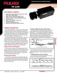
User manual (PDF) - JAI Pulnix
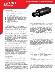
User manual (PDF) - JAI Pulnix
User manual (PDF) - JAI Pulnix

Create successful ePaper yourself
Turn your PDF publications into a flip-book with our unique Google optimized e-Paper software.
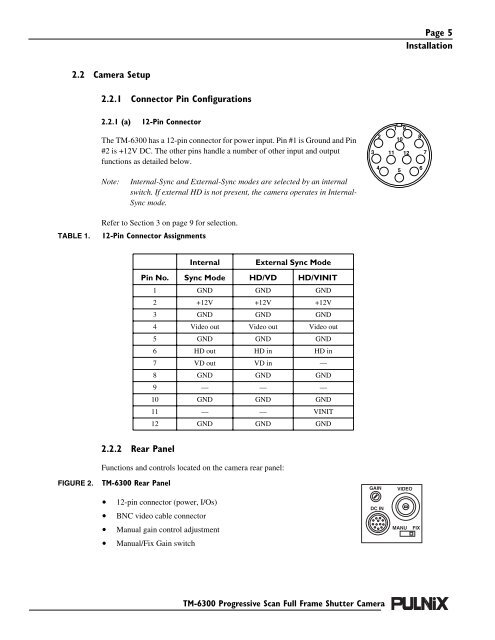
Page 5<br />
Installation<br />
2.2 Camera Setup<br />
2.2.1 Connector Pin Configurations<br />
2.2.1 (a) 12-Pin Connector<br />
The TM-6300 has a 12-pin connector for power input. Pin #1 is Ground and Pin<br />
#2 is +12V DC. The other pins handle a number of other input and output<br />
functions as detailed below.<br />
Note:<br />
Internal-Sync and External-Sync modes are selected by an internal<br />
switch. If external HD is not present, the camera operates in Internal-<br />
Sync mode.<br />
3<br />
2<br />
4<br />
1 9<br />
10<br />
11 12<br />
5<br />
8<br />
6<br />
7<br />
TABLE 1.<br />
Refer to Section 3 on page 9 for selection.<br />
12-Pin Connector Assignments<br />
Internal<br />
External Sync Mode<br />
Pin No. Sync Mode HD/VD HD/VINIT<br />
1 GND GND GND<br />
2 +12V +12V +12V<br />
3 GND GND GND<br />
4 Video out Video out Video out<br />
5 GND GND GND<br />
6 HD out HD in HD in<br />
7 VD out VD in —<br />
8 GND GND GND<br />
9 — — —<br />
10 GND GND GND<br />
11 — — VINIT<br />
12 GND GND GND<br />
2.2.2 Rear Panel<br />
Functions and controls located on the camera rear panel:<br />
FIGURE 2.<br />
TM-6300 Rear Panel<br />
GAIN<br />
VIDEO<br />
• 12-pin connector (power, I/Os)<br />
• BNC video cable connector<br />
DC IN<br />
• Manual gain control adjustment<br />
MANU<br />
FIX<br />
• Manual/Fix Gain switch<br />
TM-6300 Progressive Scan Full Frame Shutter Camera